

Page 1
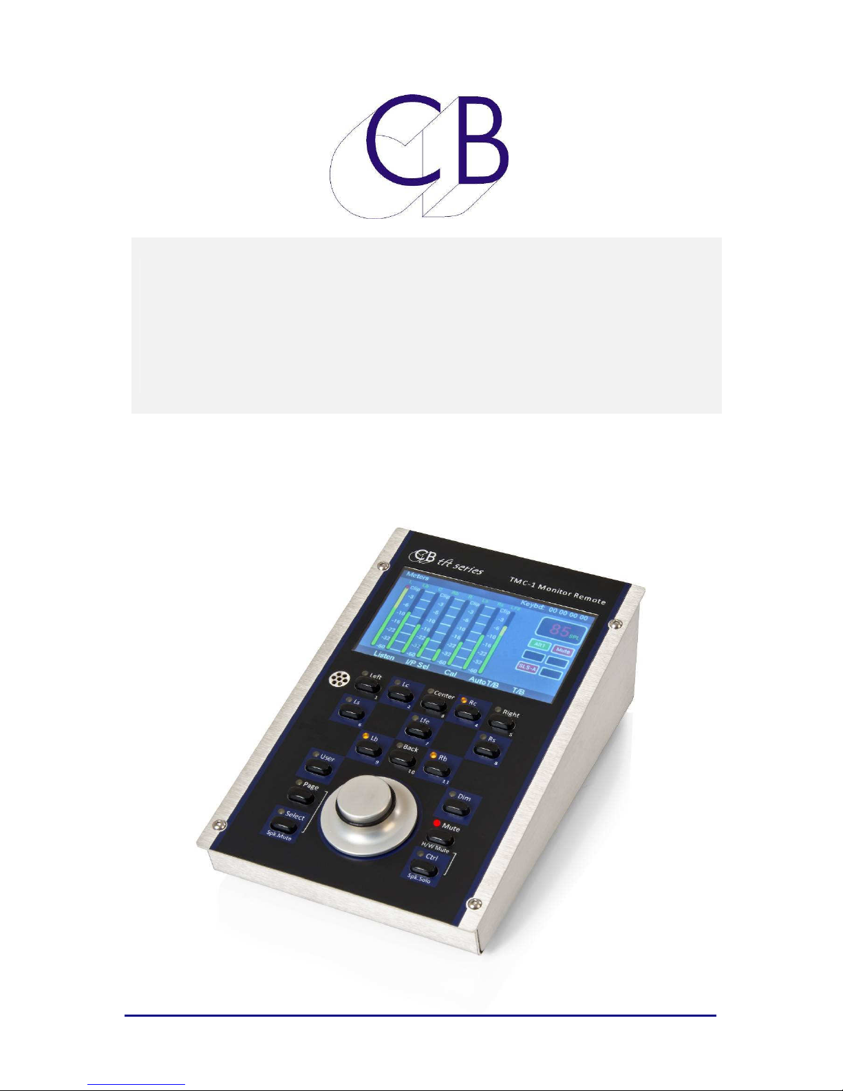
Technical
Guide
CB Electronics
TMC-1 Monitor Remote
Release
Version 1.0
Page 2

TMC-1 Monitor Controller CB Electronics
C
B
C
CB Electronics has made every effort to ensure the accuracy of information contained within
this document, which is nevertheless supplied for information purposes only and does not
constitute any form of warranty or guarantee.
All trademarks acknowledged.
The information in this document is subject to change without notice.
Elleeccttrroonniiccss
B
E
CB Electronics
Loddonside, Lands End House
Beggars Hill Road
Charvil
Berkshire RG10 0UD
Tel: +44 (0)118 9320345
Fax: +44 (0)118 9320346
Email: [email protected]
Tech Support: +44 (0)118 9320345
Web: www.colinbroad.com
Page 3

TMC-1 Monitor Controller Contents
Coonntteennttss
C
CB ELECTRONICS 2
CONTENTS 3
INTRODUCTION 1
CONNECTIONS 2
INSTALLATION 3
Connecting to XMon 4
SETTING UP TMC-1 AND XMON FOR THE FIRST TIME OR AFTER SOFTWARE
UPDATE 5
Factory Default: 5
T/B Gain 1 & 2 5
Listen Gain 1 & 2 5
AFL Gain 5
P
ROTECTED/CALIBRATED SETTINGS
Input Trim: 5
Speaker Trim: 6
Mono Trim: 6
5.1 Trim: 7
Cal A/B Trim: 7
5
OPERATION 8
Meters Page: 8
Cue Sends Page: 8
Input Select/Mute: 9
Stem/Input Solo Page: 9
Speaker Mute: 9
Speaker Solo Page: 10
Select Page: 10
In/Out Preset 10
Information display: Shown Below 11
Auto Mode: 12
Auto Mute Page: Key 2 12
User Keys, GPIO’s and Auto: 13
Setup Menu: Key 8 13
Page 4

TMC-1 Monitor Controller Contents
T/B, L/B, AFL Page: Key 5 14
TMC-1 C
M
ETERS PAGE
C
UE SENDS PAGE
ONTROLS
[Mute]: 15
[Dim]: 15
[Page]: 15
Select & Ctrl Keys: 16
[Select/Sp.Mute] Key: 16
[Ctrl/Sp.Solo] Key: 16
[User]: 16
Function Keys: Fn-1, Fn-2, Fn-3 16
User Function Keys: 17
Knob Push 19
Display Keys [1] – [8] 20
Listen 1 [1] and Listen 2 [6]: 21
User keys: [1], [2], [3], [4], [5], [6], [7], [8]: 21
User keys: [1], [5], [6], [8]: 22
[ < (2)] and [ > (4)]: 22
Mute[3]: 22
Mon [7]: 22
[Select] 22
Mute page 23
Speaker Select keys [1]-[8]: 23
Stem.Input Select keys [1]-[8]: 23
[Speaker(9)] 23
[Stem (10)] 23
Solo Page 24
In/Out Page - Speaker [3]: 24
15
21
22
TALKBACK 25
Internal Talkback and Listen-back Latching [1] and [6] 25
TMC-1 Internal/External Microphone Gain adjust 25
SYSTEM SETUP 26
Setup Menu: 26
Menu 01 – User key and setup Select 26
Menu 02 – Volume Knob push switch Function 27
Menu 03 – Page key function 27
Menu 04 – Meter Order 27
Menu 05 – Talkback Latch Enable 28
Menu 06 – Stereo Input 28
Menu 07 – Stereo Output 28
Menu 08 – TFT Brightness 29
Page 5

TMC-1 Monitor Controller Contents
Menu 09 – Top Display 29
Menu 10 – Hui AFL Enable 29
Adv Menu 01 – Lock/Un-Lock User Keys 30
Adv Menu 02 – Calibration Mode Enable 30
Adv Menu 03– External T/B Dim 30
Adv Menu 04 – Alt Output Select 30
Adv Menu 05, 06, 07, 08, 09,10 – GPI Inputs 31
Adv Menu 11 – AFL/PFL GPIO Input Active level 32
Adv Menu 12 – GPIO Record Tally Active Level 32
Adv Menu 13 – GPIO Play Tally Active Level 32
Adv Menu 14 – Action on Menu Exit 32
TMC-1-P
TMC-1-XM
ENTA ADVANCED MENU’S
Adv Menu 15 – Master Slave 33
ON ADVANCED MENU’S
Adv Menu 15 – Stereo Input to Studio L/S via Cue Input 3 34
Adv Menu 16 – Studio L/S Monitor via Stereo Input 4 34
Adv Menu 17 – Communications 34
33
34
GPIO 35
C
ONNECTING TO THE AVID
S6 36
USB PORT 37
P
OWER
37
HUI E
MULATION
MIDI T
IMECODE
F
IRMWARE UPDATES
R
ECOVERY
S
ETTING THE
S
ETTING THE INPUT, OUTPUT, SPEAKER, METER AND USER NAMES
37
37
37
38
TMC-1
USER KEY FUNCTI ONS
39
39
DIMENSIONS 40
CORRECTED XMON 15 PIN CONNECTIONS 41
OPTIMISING XMON PERFORMANCE 44
XMON CUE 3 & STEREO 4 46
XMON BLOCK DIAGRAM 47
GLOSSARY 48
Page 6

TMC-1 Monitor Controller Introduction
IInnttrroodduuccttiioonn
The TMC-1 Monitor Controller is supplied with different software to suit the system controlled.
This document describes the operation with the Avid XMon Monitor Control Unit.
Features
This guide will introduce the TMC-1 with examples and illustrations
• Connects to XMon via 15 pin ‘D’ connector (1:1).
• Supports all XMon functionalities
• Protected calibration settings
• Internal Talkback Microphone
• Play tally from Play GP Input, MTC, HUI or LTC
• Record/Red Light GP Input/Output
• Record Tally from Record GP Input or HUI
• Auto-Mute Main LS, Studio LS, Talkback and Listen Back
programmable from Play and Record GPIO
• Before, During and After automation of Studio L/S and Headphone
Output.
• Two separate talkback destinations via GP Outputs
• Dual Calibration Settings of 85 and 80 SPL
• Dedicated speaker solo/mute keys.
• GPIO for Talkback, Listenback, PFL/AFL
• Control of Cue 3 Input and Cue 3 Output
• Stem mixing with Mute and Solo (2x8 track Stems and 4x Stereo
Stems
• Route Studio L/S to Monitors via Stereo Input 4
• Send Stereo input to Cues via Cue input 3
• A/B Input and Output selection
Further information and software upgrades can be found at
www.colinbroad.com/cbsoft/tmc1/tmc1.html
22 June 2015 CB Electronics 1 Version 1.1
Page 7

TMC-1
Coonnnneeccttiioonnss
C
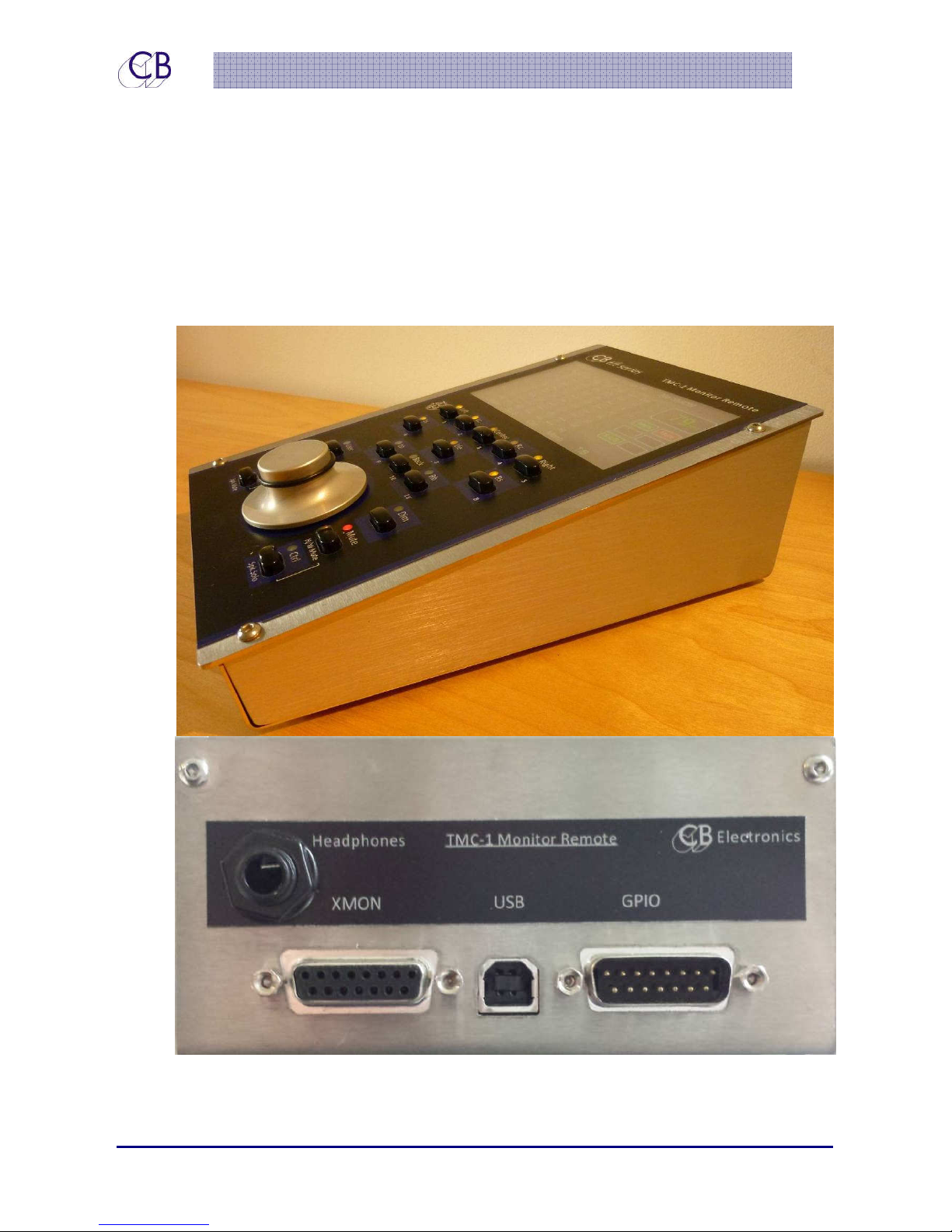
The TMC-1 has four connectors on the rear as follows
• 15 pin ‘D’ female: XMon connection including RS-422 or MIDI, Headphone, and
Microphone. The XMon communications are via MIDI or RS-422. We have tested this
with both 5m and 10m cables. If using the talkback Mic in the TMC-1, you may need
to screen this separately, as the XMon input is unbalanced.
• USB: Used for Power and if connected to MIDI on a DAW, this is used with MTC or HUI
for auto talkback and Timecode Display.
• ¼” Jack: Headphone Cue monitor connection to X-Mon via 15 pin ‘D’.
• 15 pin ‘D’ Male: GPIO in/out – Talkback 1 and 2 Enable/Selection, PFL/AFL enable,
H/W Mute output, LTC input, Play Input, Rec/Red light in/out.
22 June 2015 CB Electronics 2 Version 1.1
Page 8
TMC-1
IInnssttaallllaattiioonn
The TMC-1 is designed as a desktop unit but may be mounted flush with the desktop. The
unit should be sited in any convenient position away from sources of moisture or excessive
heat. The TFT display brightness may be adjusted via the Setup menu to optimise viewing
under different lighting conditions.
Figure 2: TMC-1 Side and Rear view
22 June 2015 CB Electronics 3 Version 1.1
Page 9

TMC-1
Connecting to XMon
The 15 pin ‘D’ Female on the rear has the same pin connections as XMon. Use the DB15
M/M cable to connect. Where necessary extend the cable. To check connections see
Appendix
Power the TMC-1 via the USB cable supplied. The TMC-1 may be powered directly from the
USB power supply or connected directly to the DAW.
Tip:
It there is a long distance between the XMon and TMC-1, use RS-422
The TMC-1 will recognize and configure XMON to the last TMC-1 setting on power up. If the
XMON is not discovered, then No XMON will be displayed in the top right of the TFT Display.
Once good communications are established with the XMON, this will then be replaced as
selected in the Setup Menu. You can select to see the XMon software revision; the software
revision number of the XMon used to develop the TMC-1 was “Version 11”.
22 June 2015 CB Electronics 4 Version 1.1
Page 10

TMC-1
Seettttiinngg uupp TT
S
tthhee ffiirrsstt ttiim
Uppddaattee
U
Factory Default:
We recommend that you start from the factory default setting. This sets all gains and Trims
at 0dB and selects the Main input and Output. To do this, you need to enter the advanced
menu – see appendix B: Selecting the Advanced menu (menu 24)
Having setup the unit to its default setting, you can then adjust each input trim as required
to achieve the required SPL level and trim the speaker outputs where necessary.
T/B Gain 1 & 2
Depress T/B 1 to adjust Talkback Microphone 1 gain [5]
Depress T/B 2 to adjust Talkback Microphone 2 gain [8]
mee oorr aafftteerr
M
C--11 aanndd
M
C
X
Moonn ffoorr
X
M
Soofftt
S
waarree
w
Listen Gain 1 & 2
Depress Listen 1 to adjust Listen Microphone 1 gain
Depress Listen 2 to adjust Listen Microphone 2 gain
AFL Gain
Press [Page] key until the [Select Page] screen is displayed. Press Levels [5] and scroll down
to AFL I/P. The gain may now be changed via the Encoder.
Protected/Calibrated Settings
To remove the protection and enable calibration select the Menu (Depress [select] and
[Page] and select [Setup], then depress [Select] and the [>] key to access the Advanced
Menus
Input Trim:
Each input has a -10db to +20dB input trim in 1dB steps.
1. Enable Calibration
22 June 2015 CB Electronics 5 Version 1.1
Page 11

TMC-1
2. Select the Meters page
3. Select the required input
4. Hold the [Select] key down, a Red Box in the lower right will display the Input Trim
5. Adjust as required whilst holding [Select] depressed
6. Disable Calibration
Speaker Trim:
Each speaker output has a +/-4dB trim in 0.5dB steps. Select the Meters page then enable
speaker Solo using the [Ctrl/Solo] key.
1. Enable Calibration
2. Select the required output
3. Solo the individual speaker
4. Hold the [Select] key down, a Red Box in the middle of the screen will display the
speaker trim
5. Adjust as required whilst holding [Select] depressed.
6. Disable Calibration
Mono Trim:
When Mono is enabled the output has a +/-4dB trim in 0.5dB steps.
1. Enable Calibration
2. Select the Meters page
3. Hold the [Mono] key depressed, a Green Box in the lower right will display the Mono
trim
4. Adjust as required whilst holding [Mono] Depressed
5. Disable Calibration
22 June 2015 CB Electronics 6 Version 1.1
Page 12

TMC-1
5.1 Trim:
When 5.1 is enabled the surround outputs have a +/-4dB trim in 0.5dB steps.
1. Enable Calibration
2. Select the Meters or Input/Output page
3. Hold the [5.1] key depressed, a Green Box in the lower right will display the 5.1
trim
4. Adjust as required whilst holding [Mono] Depressed
5. Disable Calibration
Cal A/B Trim:
The factory reset value for Cal A is 85 and Cal B is 80. However, these values can be
adjusted when calibration is enabled.
1. Enable Calibration Mode
2. Hold Cal A or Cal B depressed.
3. Adjust as required
4. Disable calibration
22 June 2015 CB Electronics 7 Version 1.1
Page 13
TMC-1
Oppeerraattiioonn
O
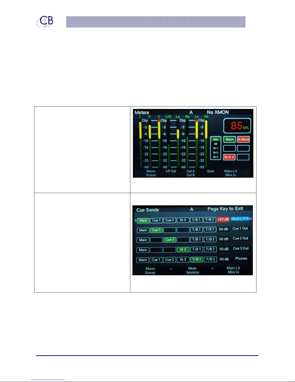
The TMC-1 control panel provides access to all the available functions of XMon. There are a
number of different pages that may be selected on the TFT Display. The Two main pages
are selected by depressing the [Page] key quickly to display the screens shown below.
The legends at the bottom of the screen correspond to the button layout of the TMC-1.
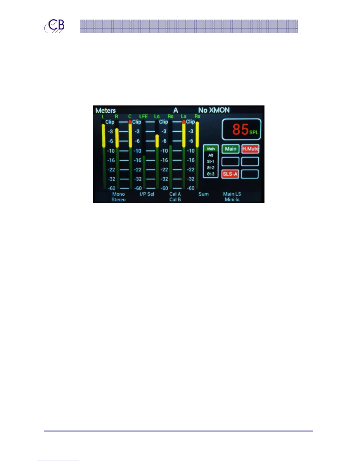
Meters Page:
The Meters page is the default page.
Depressing the Page key will always
return to the Meters page
When the Meters page is displayed
the [Select] key will enable the
Speaker and Input Mute selection.
The [Ctrl] key will enable
Speaker/Input Solo. [Select] returns to
the Meters screen.
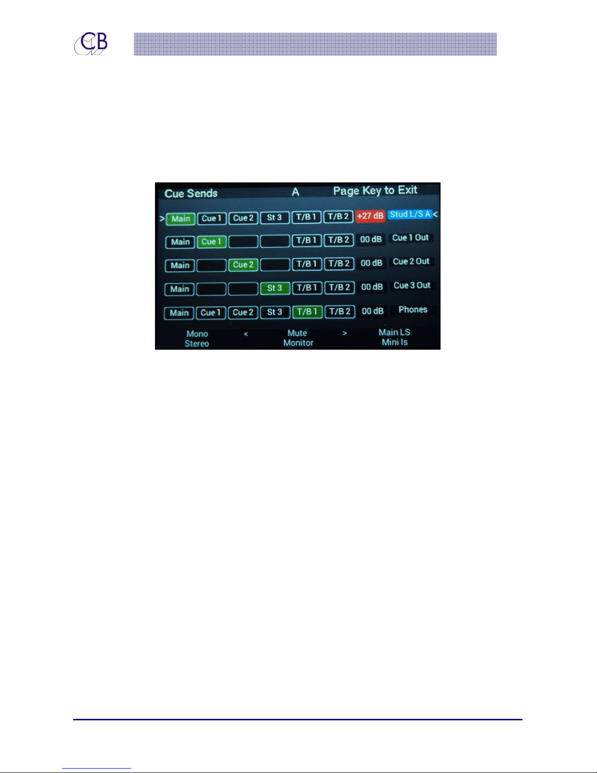
Cue Sends Page:
Depress the Page key from Meters
page will select the Cue Sends page.
When displayed the [Select] key will
enable the source selection for the
selected cue output.
[Mute}(Key3 ) mutes the selected
feed (press [Select first]. When Studio
L/S is selected [Monitor](Key7) will
select Stereo 4 input (See Menu –
Stereo 4)
22 June 2015 CB Electronics 8 Version 1.1
Page 14
TMC-1
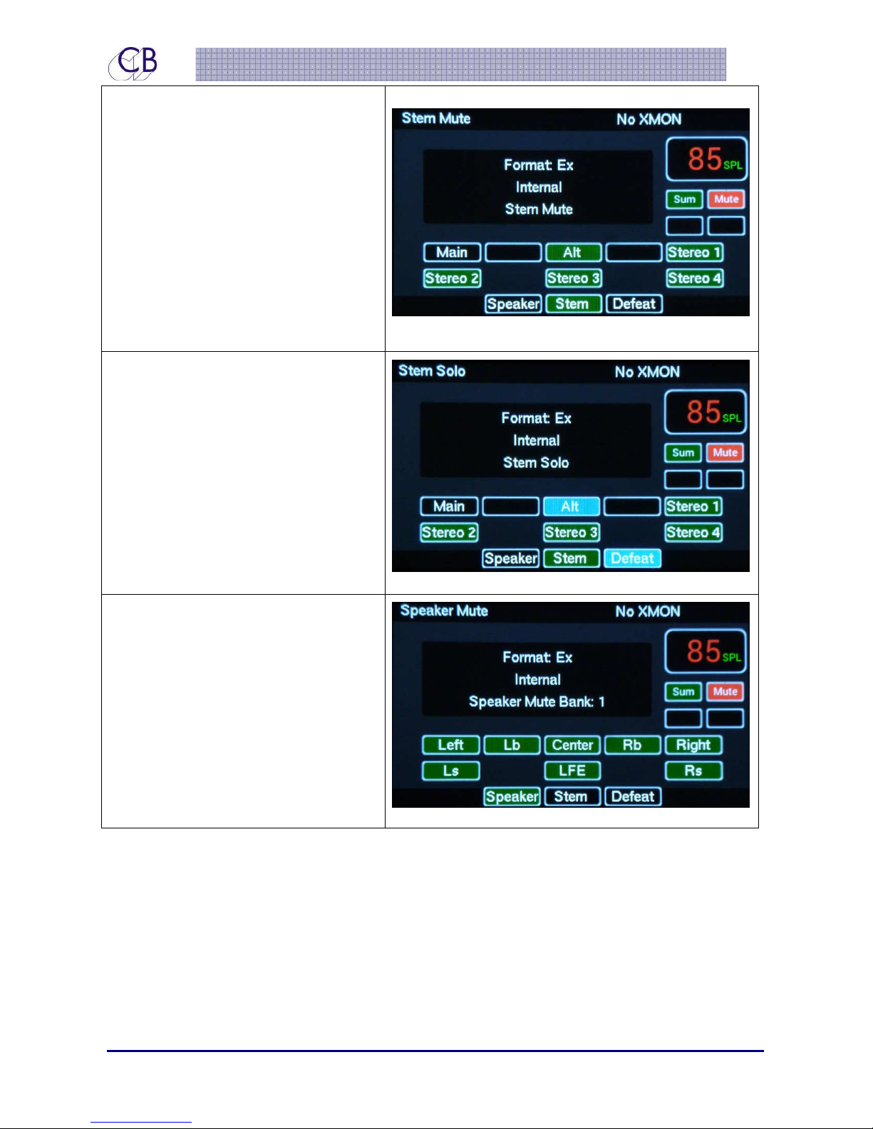
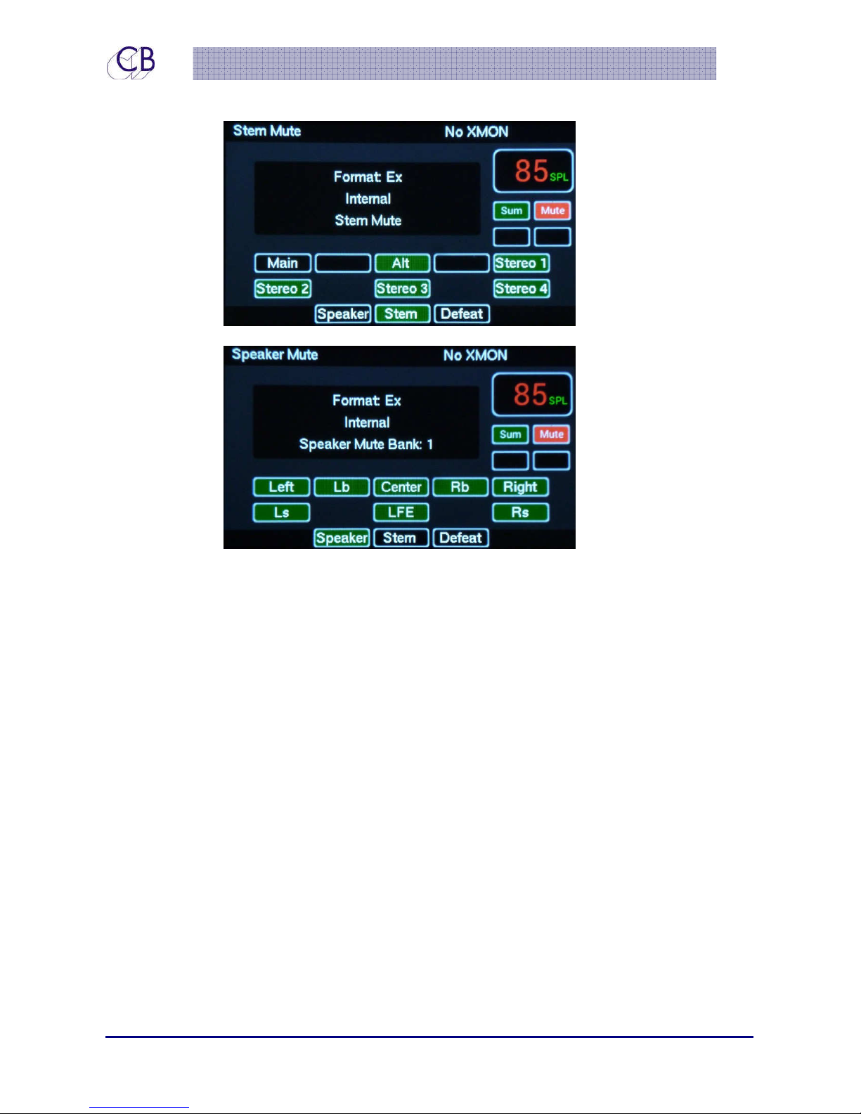
Input Select/Mute:
The [Select] key on the meters page
will select the Input Select/Mute
page. Use keys [1] to [8] to
enable/disable Inputs.
If [Speaker(9)] is lit, [Stem(10)], will
select Stem Mute.
NOTE: [Page] or [Select]returns to
Meters page
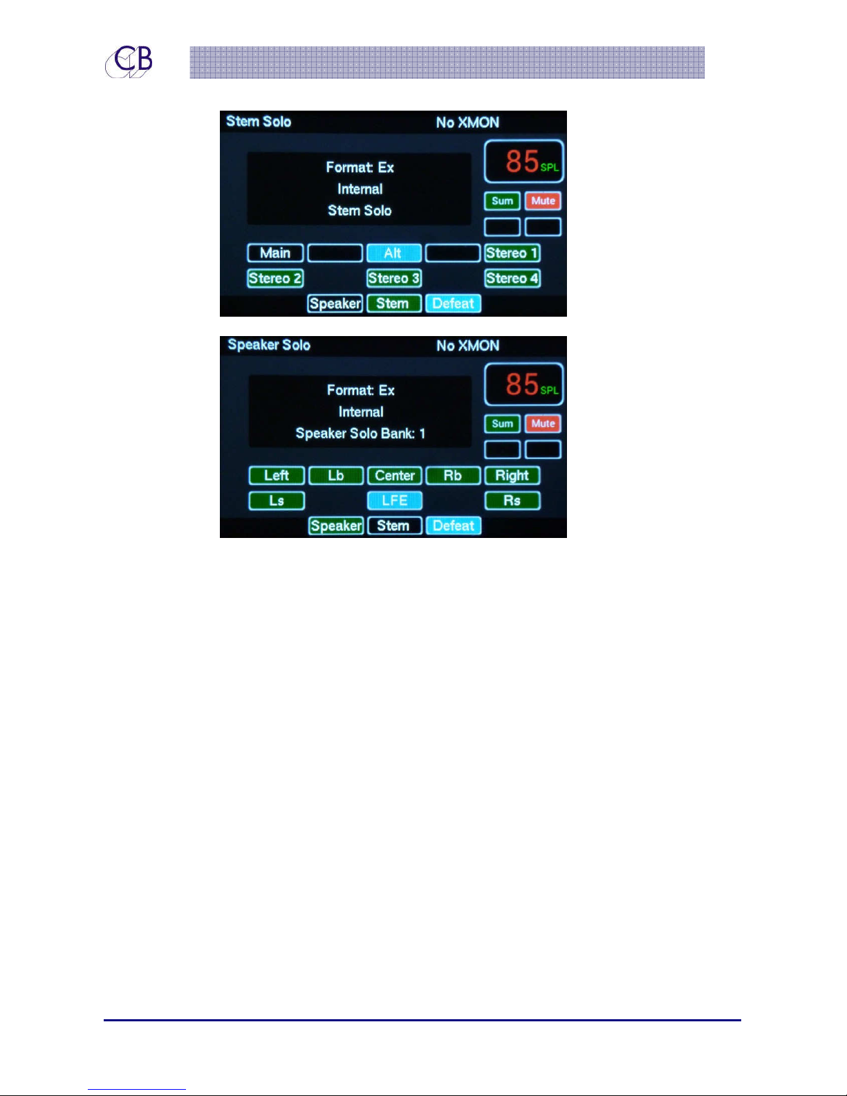
Stem/Input Solo Page:
The [Ctrl] key on the meters page will
select the Stem Solo page. Use keys
[1] to [8] to Solo Stems.
NOTE: [Page] or [Ctrl] returns to
Meters page
If [Speaker(9)] is lit [Stem(10)] will
select Stem Solo
Speaker Mute:
The [Select] key on the Meters will
enable the Speaker Mute page. Use
keys [1] to [8] to enable/ disable
Outputs.
If Input Mute is displayed, key [9] will
select Speaker Mute.
22 June 2015 CB Electronics 9 Version 1.1
Page 15
TMC-1
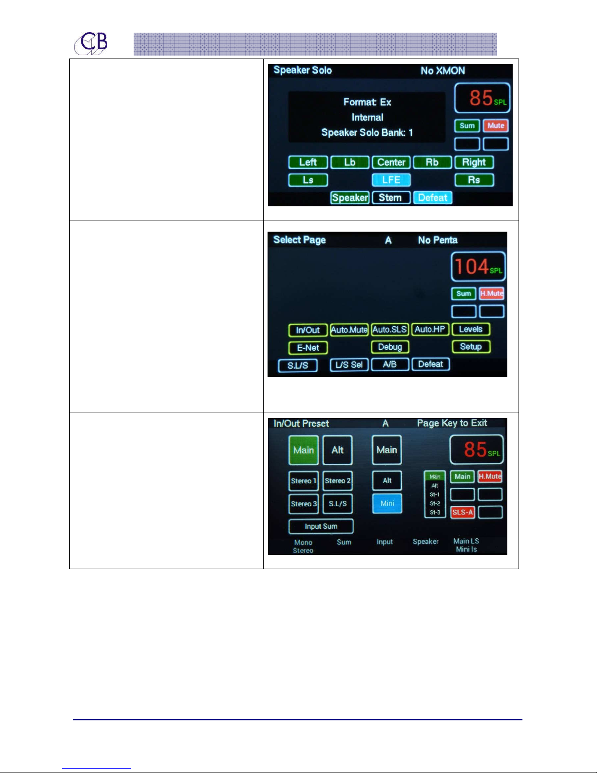
Speaker Solo Page:
The [Ctrl] key on the Meters page will
enable the Speaker Solo page. Use keys
[1] to [8] to enable/ disable Outputs.
If [Stem (9)] is lit, [Speaker (9)] will
select Speaker Solo.
[Defeat (11)] clears any Solo function
Select Page:
Depressed the [Select] and [Page}
key will access the Page Select
Screen as Shown. The keys
highlighted in yellow will access the
relevant screen.
This screen also displays the current
function for the [User], [Fn-1], [Fn-2]
and [Fn-3] keys (formerly Lb, Back,
Rb)
In/Out Preset
The Sum key enables/disables the
Sum Mode. If Sum is not enabled,
then the Input key selects the
individual inputs. If Sum is enabled,
the Input key will display the input/
stem mute page.
22 June 2015 CB Electronics 10 Version 1.1
Page 16
TMC-1
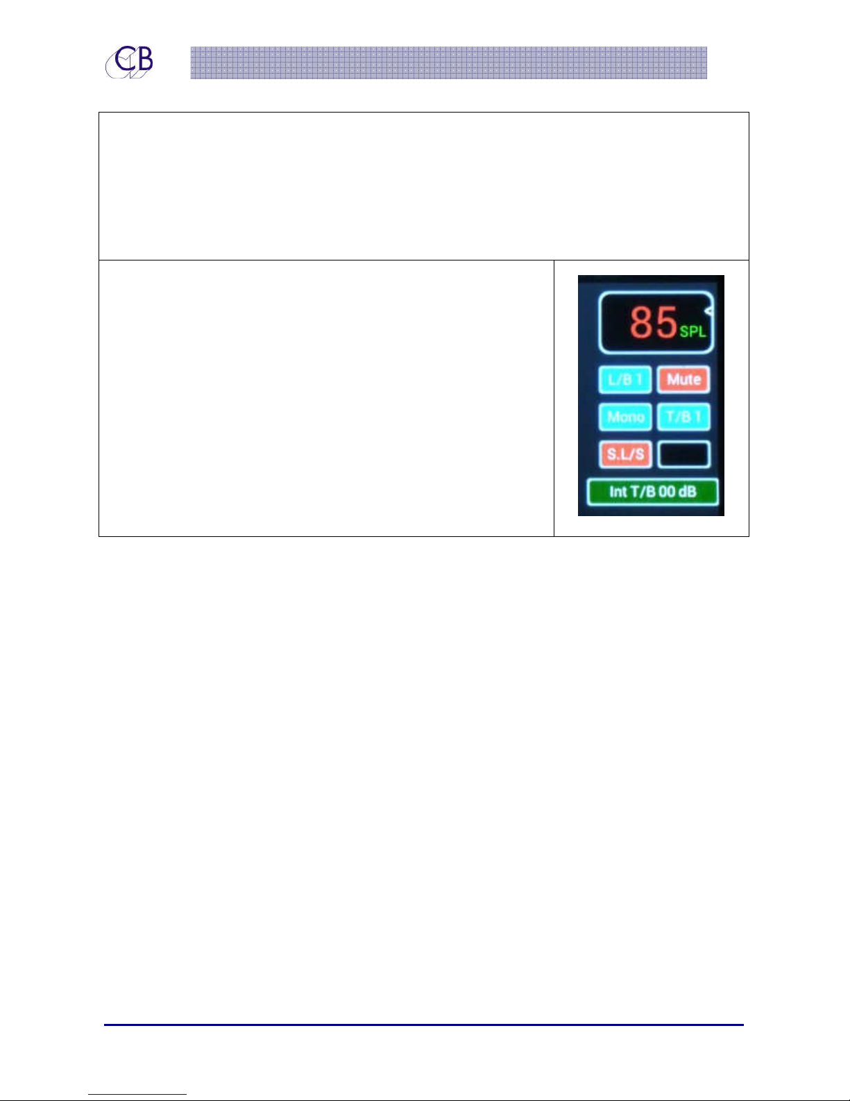
Information display: Shown Below
Having selected several pages, you will have noted that the right hand section of the
display is repeated in all but one of the above displays. This Section displays the following
information
NOTE: Switch functions can be momentary or latching
• SPL Level
• Selected Source including Listen back
• Mute/Dim
• Mono on/off
• Talk/Back on/off
• Studio Loudspeaker on/off
• Encoder control destination if not the Main output level.
In this case, the encoder controls Internal T/B Gain.
22 June 2015 CB Electronics 11 Version 1.1
Page 17
TMC-1
Auto Mode:
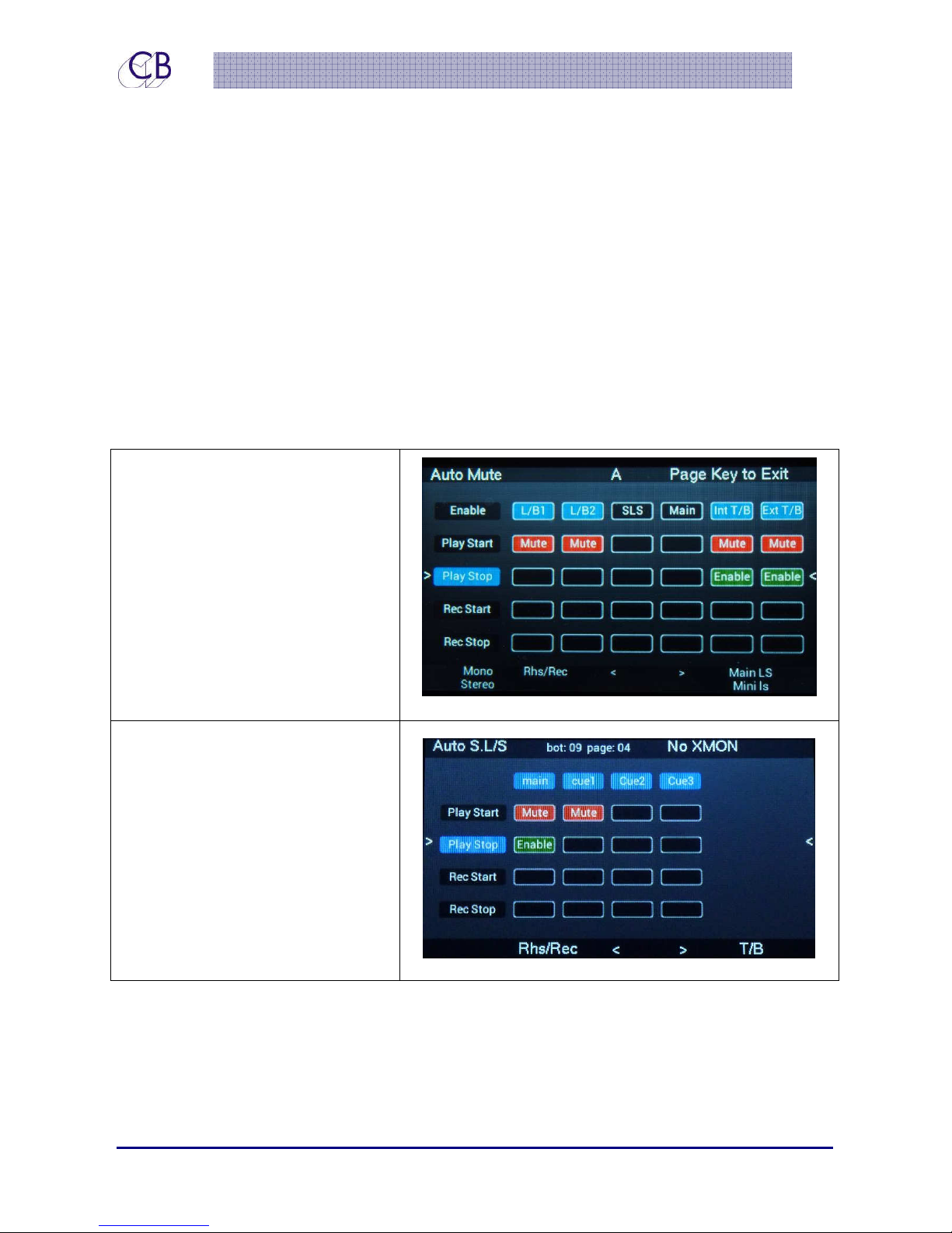
The Auto Mode pages (shown below) can be selected from the Select Page screen
({Select} + [Page] to access) , You can switch back to the Meters page at any time using
the [Page] key alone.
The Auto mode is controlled by transport tallies; two GPI inputs are provided Play and
Record and Hui via the USB port. If there is no Play tally output from your DAW you can use
either MTC via the USB connector or LTC via the GPIO connector as a play tally. You can
change the polarity of the GPIO inputs in the Setup menu. You can also program the User
key to act as a Play or record Start/Stop.
For each output there is an enable key (Blue = Enabled) and then Play Start, Play Stop,
Record Start, Record Stop, where you can determine the action. This provides an
equivalent to the Before/During/After selection used in the USA
Auto Mute Page: Key 2
Enable/disable different outputs
on state change there are three
choices on change of state 1) No
Change, 2) Mute, 3) Enable. The
action is only performed on
change. To set, select line using
[<] and [>] then depress the Select
key. The Enable line is used to
enable disable individual colums
Auto Studio L/S: Key 3
Before, During and After style monitor
control of Studio L/S output.
Switching on change of state as per
Auto mute. To set, select line using
[<] and [>] then depress the Select
key for Off/Mute/Enable of the
selected sources.
22 June 2015 CB Electronics 12 Version 1.1
Page 18
TMC-1
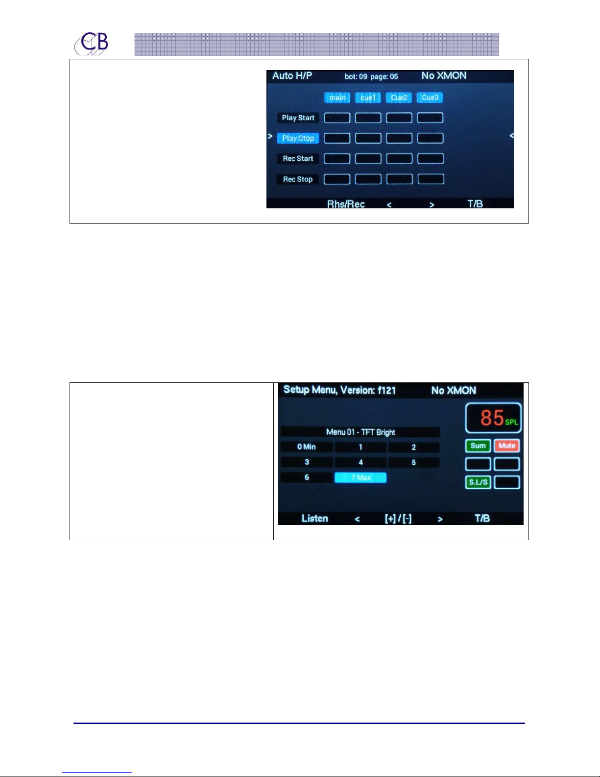
Auto Headphones: Key 4
Before, During and After style
monitor control of the headphone
output. Switching on change of
state as per Auto mute. To set,
select line using [<] and [>] and
then depress the Select key to
choose the sources.
User Keys, GPIO’s and Auto:
The User key can also be used as a Manual Red Light Control. At the beginning of a record
pass, you can disable both Listen back and Talkback, mute the studio speakers and enable
the Red light (Record/Red Light GPIO Output) from one key.
Setup Menu: Key 8
The Setup menu is selected from the Page Select ({Select} + [Page] to access). To exit the
Setup page, use the Page key to return to the Meters page.
The Setup menu is described in more
detail later in this manual. The [<] and
[>] keys select the menu page, the [+]
and [-] keys (keys [3] and [7]) change
the selected value. The [Listen] key
enables/disables Listen back and the
[T/B] key enables/disables talkback;
the associated LED indicates status.
The remaining pages are available from the Select Page screen. As usual, depressing the
[Page] key alone will return you to the Meters page. The most important extra page is
shown below [Levels]
22 June 2015 CB Electronics 13 Version 1.1
Page 19
TMC-1
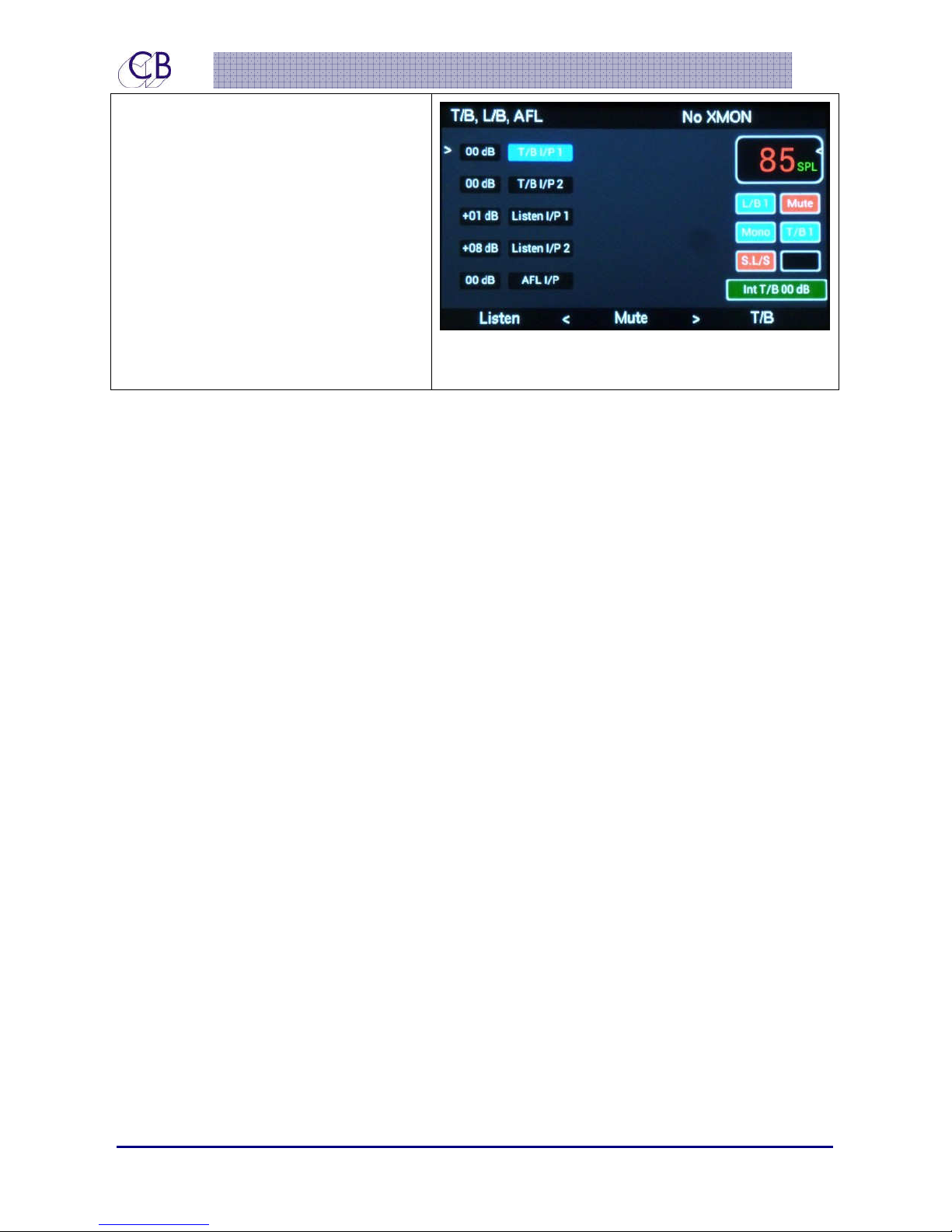
T/B, L/B, AFL Page: Key 5
On the Talkback and Listen page you
can see the gains for each input
displayed, including AFL. The Green
box on the lower Right of the screen is
displayed whenever the Encoder is not
controlling the Monitor Volume. In this
case, Talkback 1 input gain has been
selected and can be adjusted via the
Encoder. Use the [<] and [>] keys to
change the selection
22 June 2015 CB Electronics 14 Version 1.1
Page 20
TMC-1
TMC-1 Controls
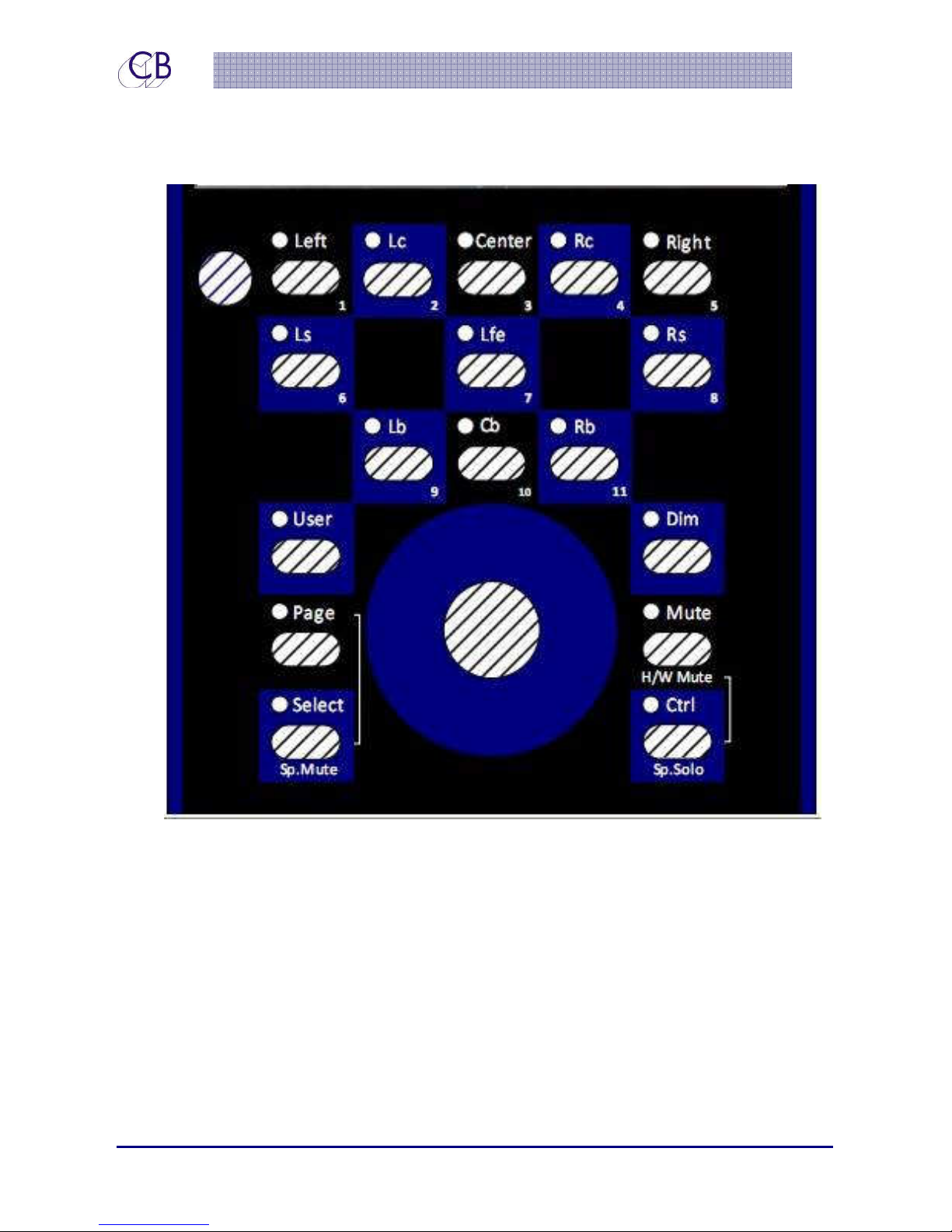
[Mute]:
Mute the Monitor output, Reset Solo Red MUTE icon
[Dim]:
Dim the Monitor output, Hold [Dim] key down to adjust the dim amount, between –
10 to -40dB in 1dB steps. A green icon with the dim value is displayed in the centre of
the screen.
[Page]:
22 June 2015 CB Electronics 15 Version 1.1
Page 21

TMC-1
Select displayed TFT page:
• Use alone to select between the two main pages – Meters and Cue Sends
• Select and Page together to display the Page select menu.
Select & Ctrl Keys:
When you depress and release the Select/Ctrl switches quickly they latch so that a second
depression will release the Select/Ctrl. When you hold the Select/Ctrl switches depressed for
a longer time the Select/Ctrl will turn off when the key is released.
[Select/Sp.Mute] Key:
The function of this key is dependant on the displayed page as follows
1) Meters Page: Selects Speaker Mute/Stem Mute page,
2) Cues Page: Use with keys[1]-[8] to select Cue Send content
3) Auto Pages: used with keys [1]-[8] to select auto function
[Ctrl/Sp.Solo] Key:
The function of this key dependant on the displayed page as follows
1) All Pages: used with the [Mute] key to enable the hardware mute and Soft Mute. The
hardware mute is disabled with the normal Mute.
2) Meters Page: Selects the Speaker Solo or Input/Stem Solo page.
[User]:
The function of the [User] key may be selected when the page select screen is displayed, Hold the
select key depressed and repeated depressions of the [User key] will select and display its function,
the LED follows on the function selected.
Function Keys: Fn-1, Fn-2, Fn-3
Switches 9,10,11, (Formerly labelled Lb, Back, Rb) these Function keys can be user-defined
from the page select screen by holding the select key depressed and repeated
depressions of the relevant key. The LEDs follow the selected function.
Function Keys - normal operation after factory Reset
[9] Speaker Select
[10] A/B - Select between two In/Out selections A and B, the Display shows the
current selection in the middle Top.
22 June 2015 CB Electronics 16 Version 1.1
Page 22

TMC-1
[11] Solo Defeat - Defeats both Stem Solo and Speaker Solo
Function Keys - Speaker/Stem Solo or Mute Page
[9] Speaker - Select Speaker Mute/Solo and Switch between speaker banks
allowing for a maximum of 32 Speakers in Digital systems
[10] Stem - Select Stem Mute/Solo
[11] Solo Defeat - Defeat both Stem Solo and Speaker Solo
Note: as XMon only has 8 channels Function key [9] will not select between speaker banks.
User Function Keys:
Not all users require the same functions, too many keys are confusing. The compromise that
we have made is to make most keys user programmable. User Keys 1-8 below the display
have two banks, you can use another key (eg. the [User] key) to select between banks. By
default the two banks are identical allowing you to change only a few keys in the second
bank.
User Keys 9, 10, 11 are not banked as their function is only displayed in the Select Page
screen.
You can also select the user keys by user or function with 5 user programmable selections,
which also include some of the setup options.
You can modify the user keys directly from the TMC-1 (You can lock this in the advanced
setup) but it is easier to use the TMC-1 configuration tool which is available for Mac or
Windows.
When programming the User keys you should remember that keys 2,3,4,7 are not available
on all screens, and that keys 1-8 are used for Speaker/Stem mute or solo.
The current user key functions are as follows
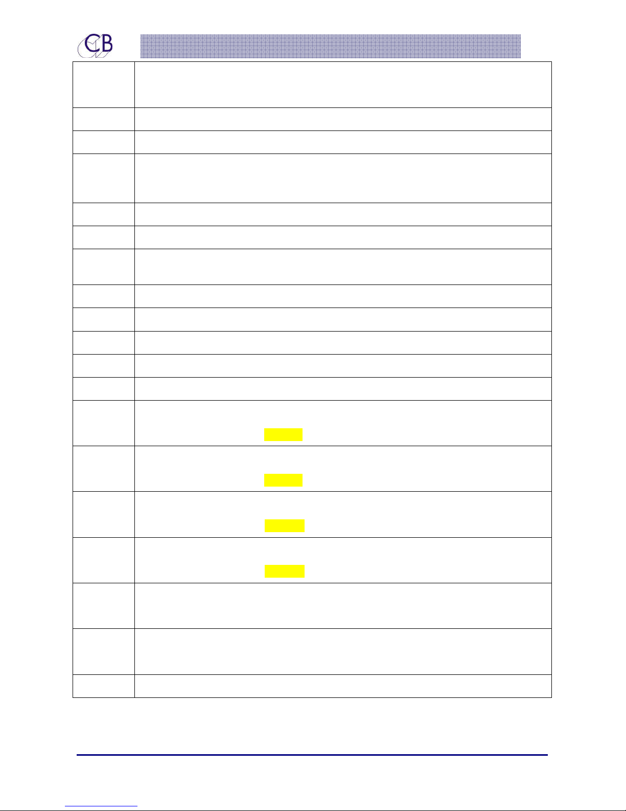
Label Function
No Function
S.L/S Studio Loudspeaker Mute On/Off
SLS A/B
The SLS A/B switch allows you to switch quickly between two different settings
for the Studio Loudspeaker feed, The current input selection is saved when you
switch and recalled when you switch back.
22 June 2015 CB Electronics 17 Version 1.1
Page 23
TMC-1
I/P Sel • Sum Disabled: step between inputs
• Sum Enabled: select Stem/Input page
Sum Enable Input Sum
Speaker Select between Main, Alt and Mini Outputs,
A/B Sel
The A/B switch allows you to switch quickly between two different input
selections, the current input selection is saved when you switch and recalled
when you switch back.
AutoT/B Enable/Disable Auto T/B, Listen, Cues
GP0-3 Enable/Disable GPOutput 3
Defeat
Defeats any active Speaker and Stem Solo. The Defeat key will also defeat any
latched talkback or Listen Back.
Cues Pg Selects the Cues page
In/out Pg Selects the In/Out Page
Main LS Select Main L/S
Alt LS Select Alt L/S
Mini ls Select Mini L/S
T/B 1 Enable Internal Talkback 1, (a quick push and release will latch)
When held down allows Internal Talkback gain adjust.
T/B 2 Enable Internal Talkback 2, (a quick push and release will latch)
When held down allows Internal Talkback gain adjust.
T/B 1x Enable External talkback Mic to T/B 1
When held down allows External Talkback gain adjust.
T/B 2x Enable External talkback Mic to T/B 2
When held down allows External Talkback gain adjust.
Listen 1 Enable/Disable Listen Inputs 1, (a quick push and release will latch)
When held down allows listen input 1 gain adjust.
Listen 2 Enable/Disable Listen Inputs 2, (a quick push and release will latch)
When held down allows listen input 2 gain adjust.
Cal A Se Set Output to Cal A – Default 85dB SPL
22 June 2015 CB Electronics 18 Version 1.1
Page 24
TMC-1
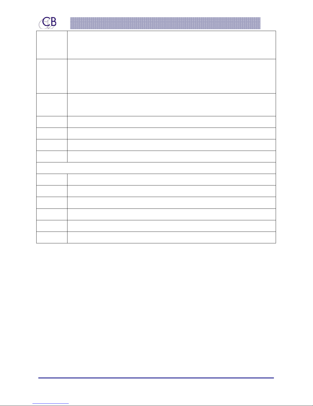
When set to Cal A repeated depressions will enable/disable the gain knob.
When the LED is lit the gain knob is disabled.
Cal B Set Output to Cal B – Default 80dB SPL
When set to Cal B repeated depressions will enable/disable the gain knob.
When the LED is lit the gain knob is disabled
U.Bank Switch User keys 1-8 between Bank 1 and Bank 2,
Note. After setting to Factory default Bank 1 = Bank 2
Mono Select Mono Output, and modify output level for mono
Stereo Select Stereo Input and Output
5.1 Select 5.1 Output, Modify Surround output levels for 5.1
7.1 Select 7.1 Output
Penta Version Only
St Down Monitor Stereo Down mix
Dn Mix Monitor Multi-track Down mix
L.Ph Inv Invert phase of Left Input
Swap L/R Swap Left and Right Outputs
Note: Both Cal A and Cal B can be adjusted +5/-10dB by first enable calibration mode.
When Cal A or Cal B is depressed, the Cal level can then be adjusted by the Encoder.
Knob Push
If any of the below are active it will clear them and require a second knob push to perform
any programmed action
Solo, Talkback, listen back, and Cal Lock
The Knob Push action can be programmed from the Setup Menu.
22 June 2015 CB Electronics 19 Version 1.1
Page 25

TMC-1
Display Keys [1] – [8]
The functions of the 8 keys in the top two rows (1..8) are defined by the selected page of
the TFT display and will depend on the selected page.
22 June 2015 CB Electronics 20 Version 1.1
Page 26
TMC-1
Meters Page
Listen 1 [1] and Listen 2 [6]:
User keys: [1], [2], [3], [4], [5], [6], [7], [8]:
User programmable, hold down [Select] and press [2] to select function, see User
Key for options
22 June 2015 CB Electronics 21 Version 1.1
Page 27
TMC-1
Cue Sends Page
User keys: [1], [5], [6], [8]:
User programmable, hold down [Select] and press [2] to select function, see User
Key for options
[ < (2)] and [ > (4)]:
Use to select the cue to me modified
Mute[3]:
Mute/Un-mute selected Cue (press Select to display Mute/Mon legends)
Mon [7]:
If Selected to Studio L/S and Menu 18 enabled, connects monitors to Stereo Input 4
[Select]
Depress to display the Cue Send enable/disable keys
22 June 2015 CB Electronics 22 Version 1.1
Page 28
TMC-1
Mute page
To select the mute page use [Select/Mute] from the Meters page, The Mute page is used to
display Speaker Mute or Stem/Input mute.
Speaker Select keys [1]-[8]:
IThe screen now displays the speaker configuration. Keys [1] – [8] will mute a selected
speaker. To switch to Solo mode, press [Ctrl/Solo].
LED’s [1]-[8] When selected to Speaker/Stem Mute or Solo, the LEDs will indicate which
Speakers/Stems are enabled
Stem.Input Select keys [1]-[8]:
Switches [1] – [6] enable /disables the inputs, [8] Enables/ disables Sum
[Speaker(9)]
[Stem (10)]
– selects the Speaker Mute Page
- selects Input/stem Mute page
22 June 2015 CB Electronics 23 Version 1.1
Page 29
TMC-1
Solo Page
In/Out Page - Speaker [3]:
Select the monitor speaker Output. If the Alt output is not used, it may be disabled
by Menu 17.
22 June 2015 CB Electronics 24 Version 1.1
Page 30

TMC-1
TTaallkkbbaacckk
The XMon has two talkback inputs, one from the controller via the 15 Way Control cable
and an external talkback input on the TB/LB/UTIL Connector. The two inputs have individual
gain settings that can be adjusted from TMC-1. The two inputs are summed within the XMon
to provide a single Talkback Output available on the TB/LB/UTIL Connector.
The TMC-1 has two Talkback Switches (5 and 8) both of which enable the internal talkback
microphone. The switches also drive Talkback 1 and Talkback 2 GP Outputs.
The external talkback microphone is enabled by up to two GPI inputs. These both enable
the External talkback microphone and also drive Talkback 1 and Talkback 2 GP Outputs.
The two Talkback GP Outputs may be used to drive relays that switch the talkback output
destination.
The Cue Send page enables T/B 1 and T/B 2 to the 5 cue send outputs
Internal Talkback and Listen-back Latching [1] and [6]
When you depress and release the Talkback/Listen-back switches quickly, they latch so
that a second depression will release the Talkback/Listen-back. When you hold the
Talkback/Listen-back switches depressed for a longer time, the Talkback/Listen-back will
turn off when the key is released.
TMC-1 Internal/External Microphone Gain adjust
Whenever the T/B 1 switch [5] on the TMC-1 is depressed, the internal Talkback Microphone
Gain is displayed at the lower right of the TFT display. The gain may be adjusted by the
Encoder.
Whenever the T/B 2 switch [8] on the TMC-1 is depressed, the external Talkback
Microphone Gain is displayed at the lower right of the TFT display. The gain may be
adjusted by the Encoder.
22 June 2015 CB Electronics 25 Version 1.1
Page 31
TMC-1
Syyssttee
S
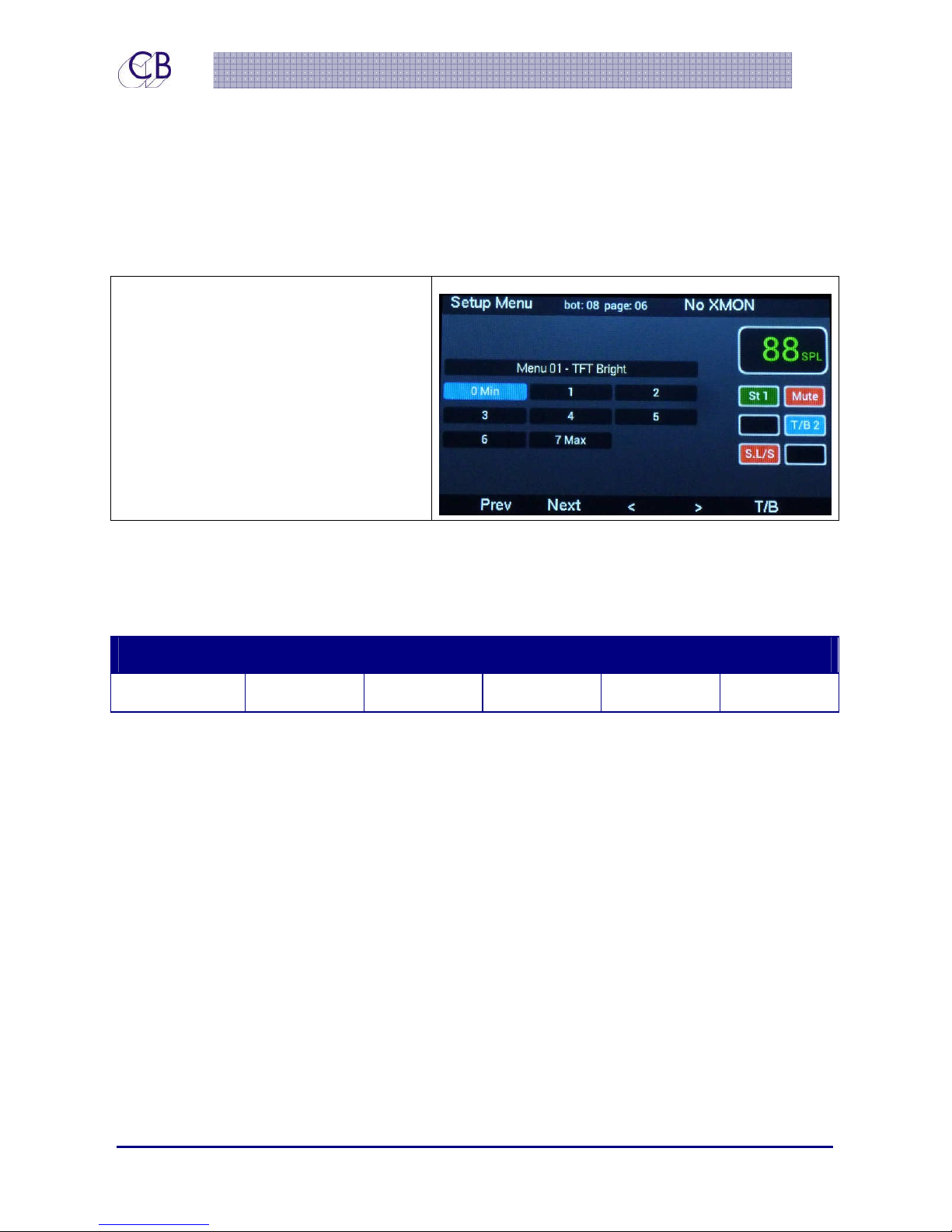
The setup menu is entered from the page select page, depress [Select and [Page] keys to
select the Page select screen and then pressing key [8] Setup
Setup Menu:
The [<](key 2) and [>](key4) keys select
the menu page, the [+](key 3) and [-
](key 7) keys change the selected
value . The [Listen] keys enable/disable
Listen-back and the [T/B] keys are used
to enable/disable talkback.
Note: S/W version at top of screen
NOTE: Confirm the selection by returning to the Meters Page
m
m
Seettuupp
S
Menu 01 – User key and setup Select
Menu 01 – User Select
Factory User-1 User-2 User-3 User-4 User-5
Recall user Keys and Setup, ‘Factory’ will reset to the last factory default setting. The user
name will be displayed in the top right of the display. The Mac/Windows setup program
may be used to set your own user names.
After Factory reset the TMC-1 will default to User-1. When an unused memory is selected
User-1 will be copied to the selected memory. If you need to reset a user memory to
factory defaults, select Factory and exit setup.
Note: All User settings and names are reset after Factory reset.
22 June 2015 CB Electronics 26 Version 1.1
Page 32
TMC-1
L C R LFE LS Rs Lb Rb
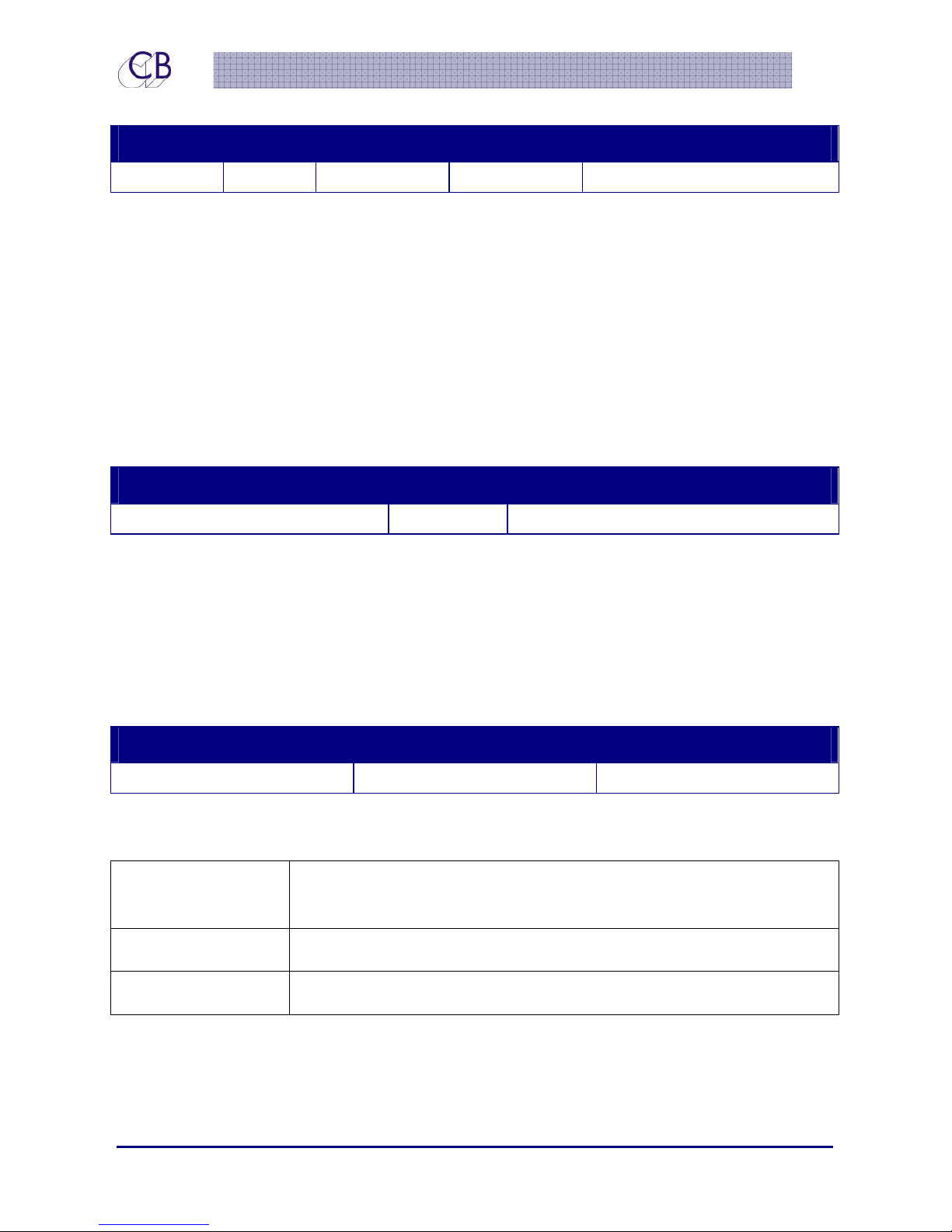
Menu 02 – Volume Knob push switch Function
Menu 02 - Knob Push
Mute Dim Cal A Cal B A/B Select
Volume Knob Push Switch Function
Mute: Mute/Unmute Speakers
Dim: Dim/UnDim Speakers
Cal A: Set Output to Cal A (why not toggle between Cal A and B?)
Cal B: Set Output to Cal B
A/B Select: Select A or B speakers
Menu 03 – Page key function
Menu 03 – Page Key Function
Cues page Off In/Out Page
The Page key is used to return to the Meters page from any other page.
This Menu defines the function of the Page key when the Meters Page is selected
Menu 04 – Meter Order
Menu 04 - Meter Order
L Lx C Rx R Ls Rs LFE
.Although the Physical layout of the channels is fixed by the hardware the meter layout can
be changed to suit the user.
L Lx C Rx R Ls Rs LFE This is the default layout and matches the physical layout of the
channels in XMon
L C R LFE Ls Rs lb Rb This layout is good for 5.1 and 7.1 and the surrounds in stereo pairs
L R C LFE Ls Rs Lb Rb This follows a standard stereo pair layout
L R C LFE Ls Rs Lb Rb
22 June 2015 CB Electronics 27 Version 1.1
Page 33

TMC-1
Menu 05 – Talkback Latch Enable
Menu 05 – Talkback Latch Enable
On Off
Talkback Latch Enable On: The Internal and External talkback keys will latch with short
depressions and no latch with long depressions
Talkback Latch Enable Off: Latching is disabled
Menu 06 – Stereo Input
Menu 06 – Stereo Input
Current St-1(Alt2) St-2(Alt3) St-3(Alt4)
The XMon does not have a stereo downmix, you must generate a stereo downmix within
Pro Tools and send to a different output.
When the [Stereo] function key is enabled this menu allows you to switch to a different at
the same time. When disabled the Input selection will switch back.
Current: Use Input selection
St-1: Use Stereo Input 1 (Alt2 on TMC-1-Penta)
St-2: Use Stereo Input 2 (Alt3 on TMC-1-Penta)
St-3: Use Stereo Input 3 (Alt4 on TMC-1-Penta
Menu 07 – Stereo Output
Menu 07 – Stereo Output
Current Alt Mini
When the [Stereo] function key is enabled this menu allows you to switch speakers at the
same time. When disabled the speaker selection will switch back.
Current: Use Current Speakers
Alt: Use Alternate speaker Output
Mini: Use Mini Speaker Output
22 June 2015 CB Electronics 28 Version 1.1
Page 34

TMC-1
Menu 08 – TFT Brightness
Menu 08 - TFT Bright
0 Min 1 2 3 4 5 6 7 Max
TFT Brightness can be adjusted to suit ambient light levels.
Note: The TMC-1 is set to full brightness on power on. There is some interference from the TFT
Backlight when not set to Max.
Menu 09 – Top Display
Menu 09 - Top Display
User LTC MTC HUI XMon Version Serial Number Keyboard
The top Right of the Display is used for error messages and useful displays, Error messages
take precedence!
User: Current user setting – not displayed if factory default
LTC: Linear Timecode via GPIO connector
MTC: Midi Timecode via USB connector
HUI: HUI position via USB connector. The TMC-1 must be selected as a HUI
Controller on the Workstation
XMon Version: XMon Software version
Serial No, Display the TMC-1 Serial number
Keyboard: Used to check the keyboard -Hex Display of up to 8 keys
Menu 10 – Hui AFL Enable
Menu 10 – Hui AFL
Off Enable
Enable/Disable Hui PFL/AFL, One of the problems on the XMon is that when enabled the
PFL/AFL is also sent to the Cue outputs when the Main output is linked to the cues. If you are
using the Hui connection to auto-switch the talkback the is allows you to decide if you wish
the outputs to switch with the AFL/PFL.
Note: If ALF/PFL is set in protocols to switch to the main output then this setting will not help.
22 June 2015 CB Electronics 29 Version 1.1
Page 35

TMC-1
Addvvaanncceedd
A
Depress the [Select] key and then the [>] key to Enter the Advanced Menu
Adv Menu 01 – Lock/Un-Lock User Keys
Un-Locked Locked
Unlocked: The user key function can be changed by holding Select down and repeated
depressions of the selected user key.
Locked: The user key functions cannot be changed
Adv Menu 02 – Calibration Mode Enable
Adv Menu 02 – Calibration Enable
Off On
Off Source Gain, Speaker Trim, Mono trim, 5.1 trim, Cal A and Cal B are Locked
Seettuupp
S
ADV Menu 01 - User Keys
On Source Gain, Speaker Trim, Mono Trim, 5.1 trim Cal Trim and 5.1 trim are enabled to
allow SPL Setting and user preferences
Adv Menu 03– External T/B Dim
Menu 03 - Ext T/B Dim
On Off
When the external talkback microphone does not cause feedback, you can disable the
Dim on Talkback function.
On: Dim Control Room Speakers when External Talkback is enabled
Off: No Dim with External Talkback
Note: Internal (TMC-1) Talkback will always dim the control room speakers.
Adv Menu 04 – Alt Output Select
Adv Menu 04 - Alt Output Select
Enable Disable
22 June 2015 CB Electronics 30 Version 1.1
Page 36

TMC-1
Enable: Speaker switching rotates between Main, Alt and Mini
Disable: Speaker switching alternates between Main and Mini, use when the Alternate
output is not connected.
Adv Menu 05, 06, 07, 08, 09,10 – GPI Inputs
Adv Menu 05 – User GP In 0
AFL/PFL
Mute Dim SLS Mute Int T/B 1 Int T/B 2
Adv Menu 06 – User GP In 1
Listen 1 Mute Dim SLS Mute Int T/B 1 Int T/B 2
Adv Menu 07 – User GP In 2
Listen 2 Mute Dim SLS Mute Int T/B 1 Int T/B 2
Adv Menu 08 – User GP In 3
Ext T/B 1 Mute Dim SLS Mute Int T/B 1 Int T/B 2
Adv Menu 09 – User GP In 4
Ext T/B 2 Mute Dim SLS Mute Int T/B 1 Int T/B 2
Adv Menu 10 – User GP In 7
Ext T/B 1 Mute Dim SLS Mute Int T/B 1 Int T/B 2
AFL/PFL: Enable AFL/PLF to Control room Monitors
Listen1: Enable Listen Microphone 1 to Control room Monitors
Listen 2: Enable Listen Microphone 1 to Control room Monitors
22 June 2015 CB Electronics 31 Version 1.1
Page 37

TMC-1
Talkback: Enable Internal Talkback Microphone and T/B GP Out 1
Ext T/B 1: Enable External Talkback Microphone and T/B GP Out 1
Ext T/B 2: Enable External Talkback Microphone and T/B GP Out 2
Mute: Mute Control room Monitors
Dim: Dim Control room Monitors
SLS Mute Mute Studio Monitors
Int T/B 1: Enable Internal Talkback Microphone and T/B GP Out 1
Int T/B 2: Enable Internal Talkback Microphone and T/B GP Out 2
Adv Menu 11 – AFL/PFL GPIO Input Active level
Adv Menu 11 – AFL/PFL GP In - 0
Low High
When active, the XMon Monitor Output is switched to the AFL input.
Adv Menu 12 – GPIO Record Tally Active Level
Adv Menu 12- Rec GP In
Low High
Adv Menu 13 – GPIO Play Tally Active Level
Adv Menu 13 - Play GP In
Low High
Adv Menu 14 – Action on Menu Exit
Adv Menu 14 - On Menu Exit
Off Factory T/B+L/B Factory T/B Only Factory NO T/B or L/B
Off: No Action
Factory T/B+L/B: Reset to factory and default user keys with T/B and L/B Keys
Factory T/B only: Reset to factory and default user keys with T/B Keys only
Factory NO T/B or L/B: Reset to factory and default user keys without T?B and L/B Keys
22 June 2015 CB Electronics 32 Version 1.1
Page 38

TMC-1
Set all variables to factory to defaults as follows
All Gains set to 0dB-Unity
Cue routing as follows
SLS – Main
Cue1 – Cue1 input
Cue2 – Cue 2 input
Cue3 – Cue 3 input
Head Phones – Talkback
Automation
Play Start – Disable Talkback and Listen Back
Play Stop –
Record Start – Disable Talkback, Listen Back and Studio L/S
Record Stop –
TMC-1-Penta Advanced Menu’s
These menus are only present on the TMC-1-Penta
Adv Menu 15 – Master Slave
Adv Menu 015 – Master/Slave
Master Slv 1 Slv 2 Slv 3 Slv 4
When connecting more than one TMC-1 to a Ax32/Penta 720 one of the units is the master
and the others slaves. If using the default ip address xxx.xxx.xxx.246 … xxx.xxx.xxx.250 this
parameter will also set the ip address as follows;-
Master xxx.xxx.xxx.250 Slv 1 xxx.xxx.xxx.249
Slv 2 xxx.xxx.xxx.248 Slv 3 xxx.xxx.xxx.247
Slv 3 xxx.xxx.xxx.246
The Master unit sends all commands to the AX-32/Penta-720 and copies tatus to all slaves
The slave units send commands to Master that will relay them to the AX-32.Penta 720.
22 June 2015 CB Electronics 33 Version 1.1
Page 39

TMC-1
TMC-1-XMon Advanced Menu’s
These Menu’s are only present on the TMC-1-XMon
Adv Menu 15 – Stereo Input to Studio L/S via Cue Input 3
Adv Menu 15 – Cue Input 3 Label
Cue 3 St 3
To independently play back a stereo source on the Studio L/S while monitoring other source
material in the control room, it can be routed to a cue input. Selecting Stereo 3 routes the
signal to Cue send 3.
Cue 3: Cue Input 3 labelled “Cue 3”
Stereo 3: Cue input 3 labelled “St 3”
Adv Menu 16 – Studio L/S Monitor via Stereo Input 4
Adv Menu 16 - Stereo 4
Input Studio L/S
To monitor any the Studio L/S in the control room connect the Studio L/S Output to Stereo
Input 4
Input: Stereo 4 input is used as normal
Studio L/S: To monitor the Studio L/S Send, connect Stereo 4 Input to the Studio L/S
output, then when selected to Studio L/S on the Cue Send Page, Switch 7 will
enable/disable.
Adv Menu 17 – Communications
Adv Menu 17 - Comms
RS422 Midi
XMon has two serial ports, RS422 and MIDI. Either can be selected.
RS422 Communication via RS-422 pins 1, 2, 9 and 10 on the XMON connector
MIDI Communication via MIDI pins 3, 4, 11 and 12 on the XMON connector
22 June 2015 CB Electronics 34 Version 1.1
Page 40
TMC-1
G
PII
G
O
P
O
Pin
GPI
GPO
No.
1 0 Input PFL/AFL Enable Menu 12 User GP In-0 Low 1
2 2 Input Listen 2 Menu 14 User GP In-2 Low 3
3 4 Input Ext T/B 2 Menu 16 User GP In-4 Low 5
Bit
No.
9 1 Input Listen 1 Menu 13 User GP In-1 Low 2
10 3 Input Ext T/B 1 Menu 15 User GP In-3 Low 4
Bit
No.
Input/
Output
Default Function Menu Selection Default
Active
Note
11 5 6 In/Out Play Tally I/O Low 6
4 6 5 In/Out Record Tally/
Red Light I/O
12 7 4 In/Out Talkback Menu 4 User GP In-7 Low 8
5 3 Out User GP Out 3 Low 9
13 2 Out Talkback 2 On Low 10
6 1 Out Talkback 1 On Low 11
14 0 Out H/W Mute Low 12
7 Ground
15 Input LTC-
8 Input LTC+
Low 7
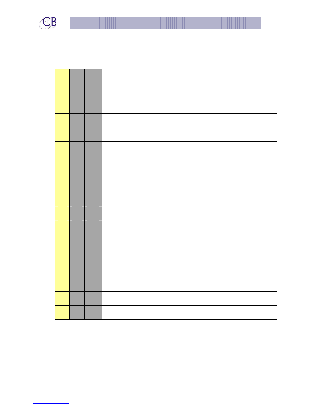
Note1. PFL/AFL Enable
Connect to the PFL/AFL control output of your console/DAW, active low input will switch
the monitor output to AFL/PFL Input.
22 June 2015 CB Electronics 35 Version 1.1
Page 41

TMC-1
Notes 10, 11. T/B 1, T/B2
XMon has only one Talkback output. These two outputs allow you to route the talkback to
two different areas.
Note 12. H/W Mute
Low when Hardware mute is enabled
Connecting to the Avid S6
See the GPIO Section of the S6 Manual. The relevant connections are:
S-6 GPIO
Function
Talkback 18 Note 3 6 12 GPI 7 I/P
Dim 19 Note 3 7 1,2,3,9,10 Note 1
Mute/Cut 20 Note 3 8 1,2,3,9,10 Note 2
Play 22 Note 3 10 11 Play Tally I/O
Record 23 Note 3 11 4 Record Tally I/O
Note 1: Dim is available as an option on any of 5 GPI inputs via menu selection
Note 2: Mute/Cut is available as an option on any of 5 GPI inputs via menu selection
Note 3: Common connection – Connect to pin 7 on TMC-1 GPIO.
S6 GPIO Connect to
TMC-1 pin 7 Ground
S6 GPIO
Pin
TMC-1 GPIO Pin
22 June 2015 CB Electronics 36 Version 1.1
Page 42

TMC-1
U
S
U
S
B
Poorrtt
B
P
Power
The TMC-1 uses about 400mA, this is within the 500mA maximum for a USB port. We
recommend that the TMC-1 is the only device connected to the port. If you are not using
the MTC or HUI functions, you can use a 5v USB power supply.
HUI Emulation
To use the HUI emulation, define the MIDI port as a HUI interface in the Workstation (DAW).
The HUI Play and Record tallies will then drive the automated switching. You can check the
interface by enabling the HUI positional display in the top line.
The Debug section includes a HUI Status display, if you find a key function that would be
useful to include in the TMC-1, please report its code and we will look into updating the
software.
MIDI Timecode
To use MTC, connect to a workstation and define it as a MIDI Port. MTC ¼ frame timecode
will enable the Play tally drive the automated switching. You can check the interface by
enabling the MTC positional display in the top line.
Firmware Updates
The USB Port is also used to update the TMC-1 firmware. Updates are posted on the TMC-1 –
Xmon or TMC-1-Penta product page:
http://www.colinbroad.com/cbsoft/tmc1/tmc1.html
http://www.colinbroad.com/cbsoft/tmc1/tmc1penta.html
You will find both a Mac and Windows version of “midiupd” on the same page which
should be used to send firmware updates to the TMC-1
Midiupd includes instructions, you can also find the TMC-1 programming guide on the web
site.
22 June 2015 CB Electronics 37 Version 1.1
Page 43
TMC-1
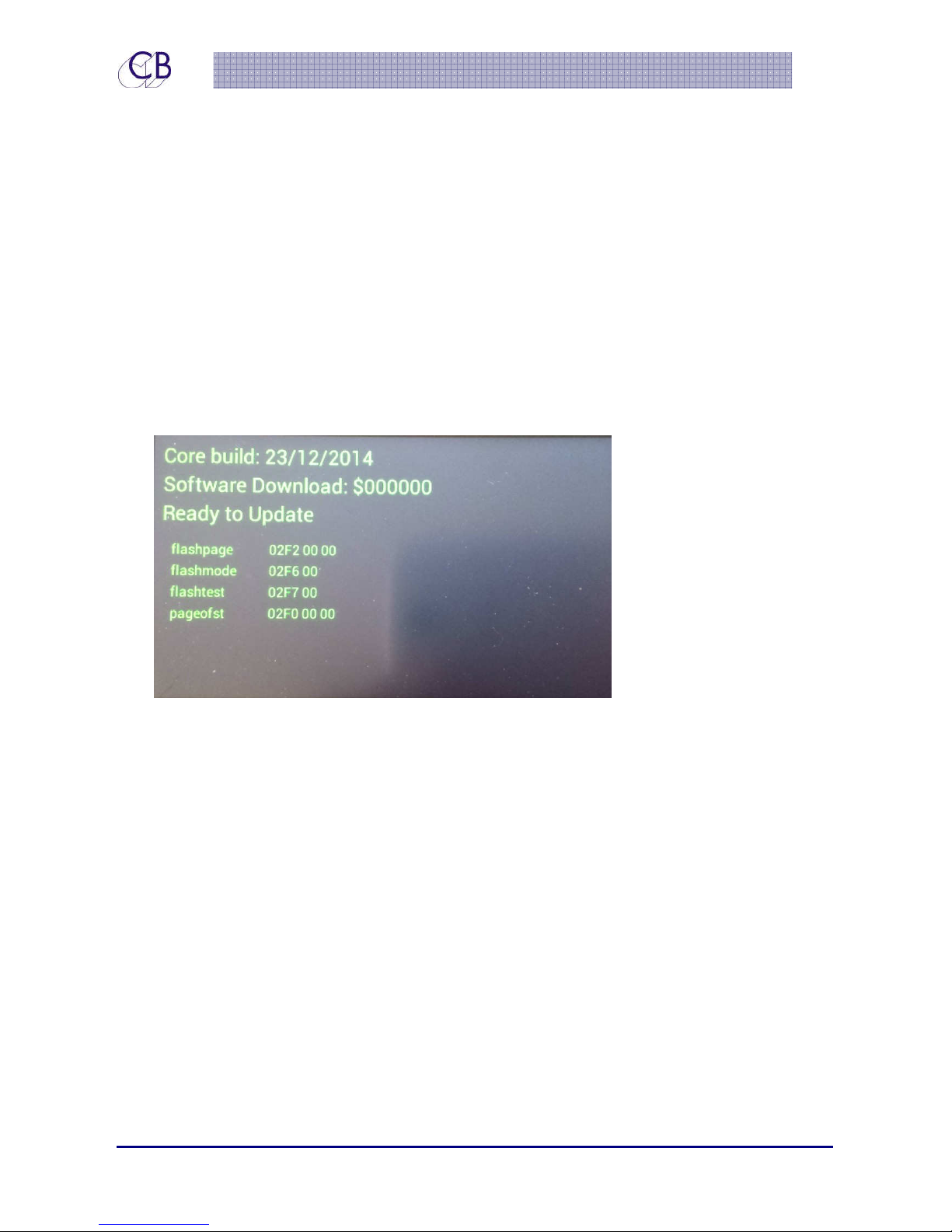
Note: the progress bar on the TMC-1 shows the total memory space available and will not
reach the end. The Progress bar on “midiupd” shows the update length and will be cleared
once finished
Recovery
In the case of power failure or other problems when updating the TMC-1 firmware.
1. Abort and exit from “midiupd”
2. Unplug the USB then reconnect whist depressing [Select] and [Ctrl]. The Software
Download screen will be displayed.
3. Restart “midiupd”. You will need to select the CBCore MIDI ports
22 June 2015 CB Electronics 38 Version 1.1
Page 44
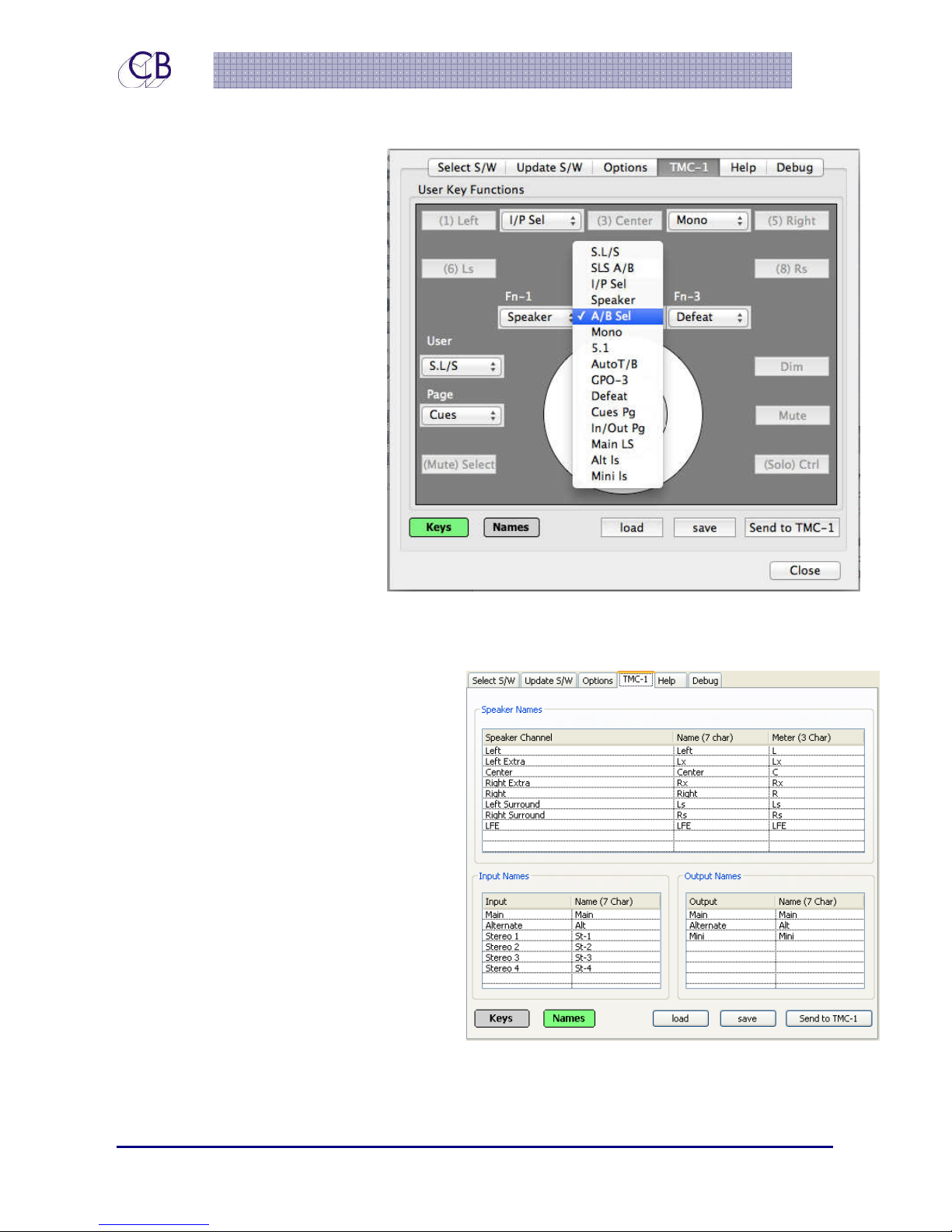
TMC-1
Setting the TMC-1 user key functions
After a factory reset the user key
functions are set to there default
function, you can change them
using MidiUpd the programming
tool (for Mac or Windows)
connected via the USB port.
Note. These user key functions
can also be set on the TMC-1
diectly
Setting the Input, Output, Speaker, Meter and User
Names
After a Factory Reset these names are set
to their Default values, you can change
them using the MidiUpd the programming
tool connected via the USB port. The Input
and Speaker names are limited to 7
characters, the Meter names to 3
characters.
Note: Although the names as key functions
are saved in the same file they are
updated individually
Note: On the TMC-1-Penta these names
are also set from the Penta definition file
except for the User names.
22 June 2015 CB Electronics 39 Version 1.1
Page 45
TMC-1
Dii
meennssiioonnss
D
m
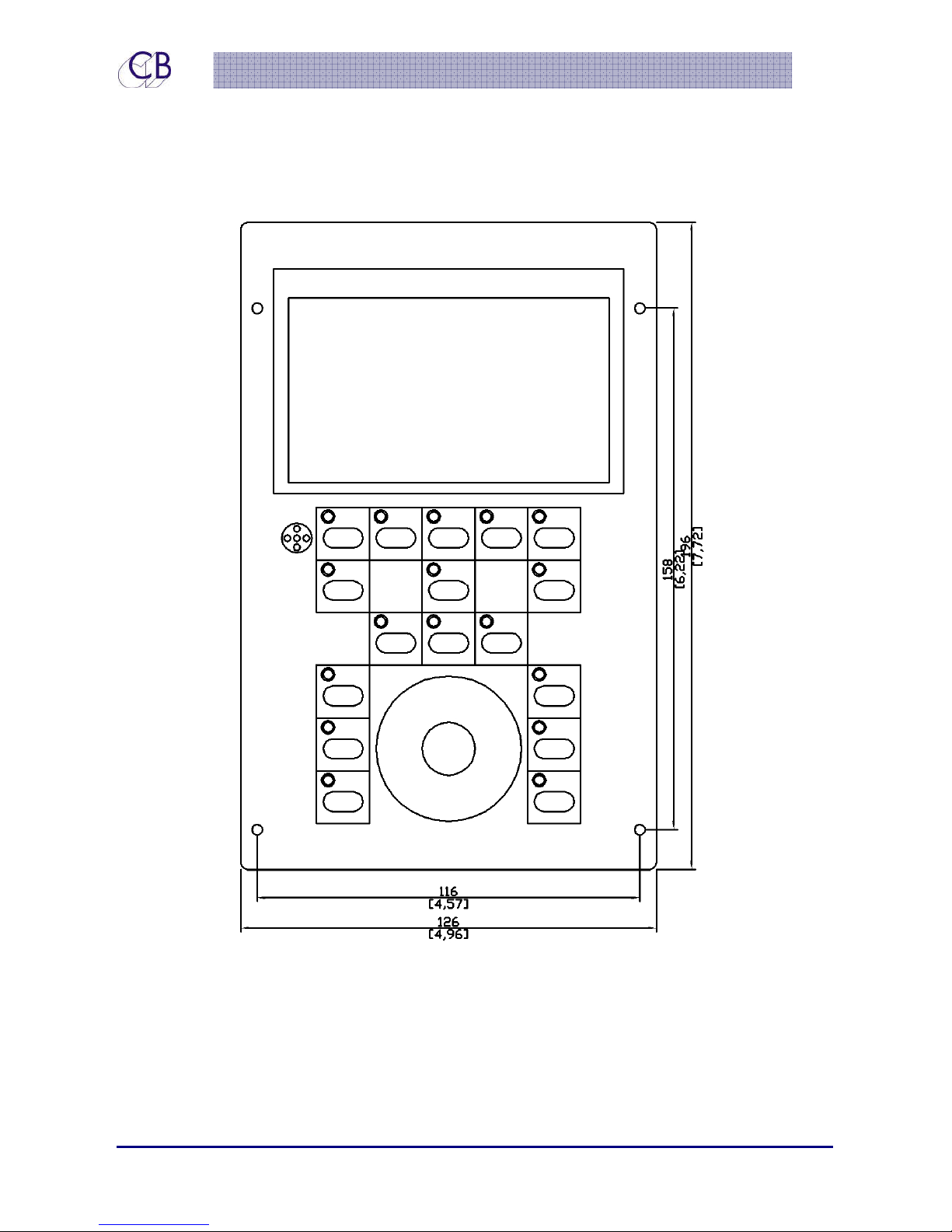
When mounting into a panel, a cut-out of 190 x 124 mm or 7.48” x 4.88” should be made.
There is a 1mm overhang on each side and a 3mm overhang at Top and bottom.
22 June 2015 CB Electronics 40 Version 1.1
Page 46
TMC-1
Coorrrreecctteedd
C
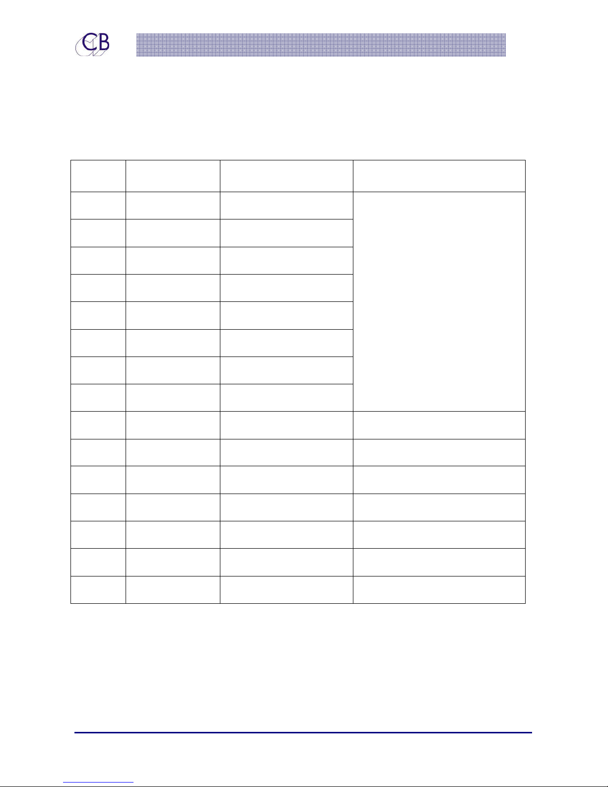
Pin No. Hardware
Configuration
1 Input RS422 Input +
9 Input RS422 INPUT -
2 Output RS422 Output +
10 Output RS422 Output -
3 Output MIDI Output -
11 Output MIDI Output +
4 Input MIDI Input -
X
Moonn 1155 ppiinn
X
M
Function Note
RS422 or MIDI Used not both –
See RS422/MIDI select in TMC-1
menu
12 Input MIDI Input +
5 Input Headphone Ground Avid Doc incorrect
13 Input Headphone Left Avid Doc incorrect
6 Input Headphone Ground Avid Doc incorrect
14 Input Headphone Right Avid Doc incorrect
7 Ground
15 Output Internal Talkback Mic
8 Ground Internal Talkback Mic J13 between pins 1 and 2
22 June 2015 CB Electronics 41 Version 1.1
Page 47
TMC-1
Coonnnneeccttiioonnss
C
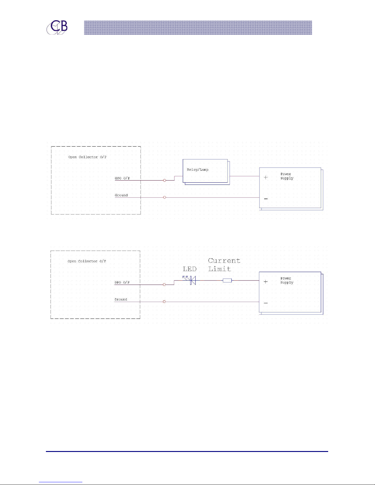
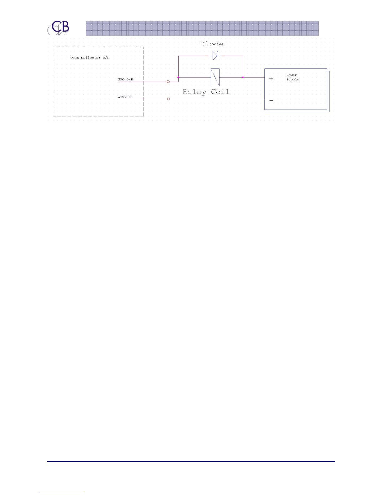
Connecting a lamp to a Open collector outputs
Connecting a LED to a Open Collector Output
The Current Limit resistor cab be calculated typically 330R for a
5v Supply and 1K for a 12v Supply.
Connecting a Relay to a Open collector output
22 June 2015 CB Electronics 42 Version 1.1
Page 48
TMC-1
The Diode id optional
22 June 2015 CB Electronics 43 Version 1.1
Page 49
TMC-1
Oppttii
O
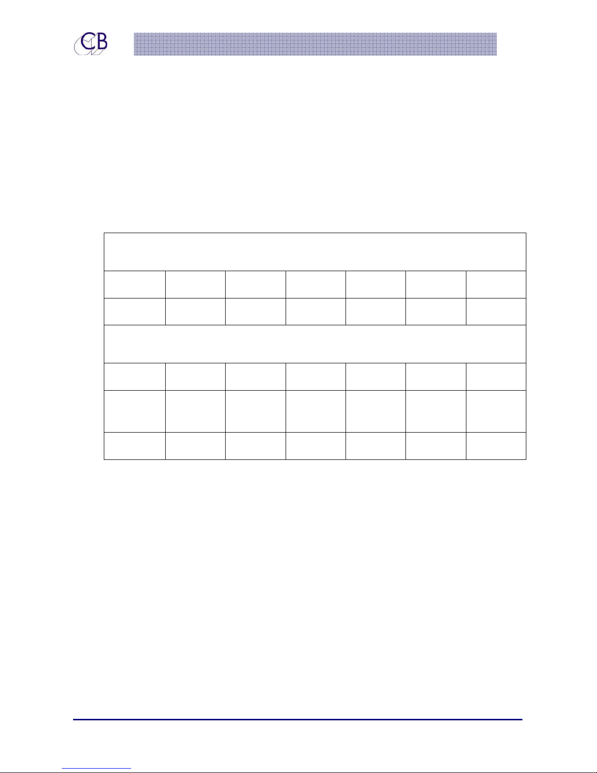
XMon cannot be considered as a standalone device but as part of a monitor system
consisting of the XMon, Power amps and Speakers.
The main gain section of XMon uses digital gain control to provide a gain range of +31dB to
-95db. As can be seen on the chart below, to optimize the signal-to-noise ratio, it is
important that XMon is run at between 0dB and +10dB gain for normal levels.
miissiinngg
m
XMon Noise and Distortion at different gains
Measured with +4dB gain and speaker trim set at -4dB (0dB overall)
Gain -30dB -20dB -10dB 0dB +10dB +20dB
Noise -95dB -94dB -94dB -93dB -83dB -73dB
Output Level, Signal to Noise and distortion
measured with +4dBm @ 2KHz Input (-16dB on XMon Meters)
-26dBm -16dBm -6dBm +4dBm +14dBm +24dBm
X
Moonn ppeerrffoorr
X
M
maannccee
m
Signal to
Noise
THD+Noise
The Speaker trim section of the XMon provides a gain range of 0dB to -63.5dB in 0.5db
steps. As can be seen in the chart below, the signal-to-noise remains the same for the first
4dB of attenuation but then the noise floor levels out so that the signal-to-noise degrades as
attenuation is increased.
66dB 76dB 86dB 97db 97dB 97dB
0.116% 0.040% 0.016% 0.011% 0.016% 0.061%
22 June 2015 CB Electronics 44 Version 1.1
Page 50

TMC-1
Speaker attenuation, Signal to Noise and distortion
Measured with +4dBm input @ 2KHz Input and +4dB gain
Speaker
0dB -2dB -4dB -6dB -8db -10dB -12dB -14dB -16dB
Trim
Noise
Output
-88.3 -90.2 -92.5 -93 -93.5 -93.8 -94.1 -94.2 -94.5
+8dBm +6dBm +4dBm +2dBm 0dBm -2dBm -4dBm -6dBm -8dBm
Level
THD+Noise 0.009 0.009 0.009 0.009 0.009 0.010 0.012 0.014 0.016
Signal to
96.3 96.2 96.5 95 93.5 91.8 90.1 88.2 86.5
Noise
Note. The increase in distortion at increased attenuation is largely due to the noise
content
The factory default settings of the TMC-1 XMon controller are as follows:
Main Gain Section +4dB gain.
Speaker Trim -4dB
Overall gain 0dB
Speaker trim range is restricted to +/- 4dB
Input makeup gain +20dB to -10dB
XMon Metering:
The default setting provides 5dB of analogue headroom above the digital clip point
when set in this mode (XMon clips at approximately +25dBm).
The X-Mon updates a channel every 2.5mSec, all channels are updated in 20mSec.
22 June 2015 CB Electronics 45 Version 1.1
Page 51
TMC-1
X
Moonn
X
M
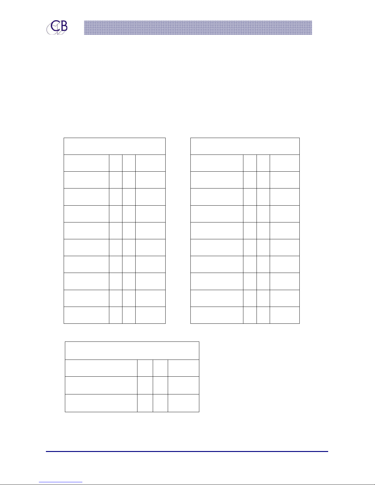
Although not always documented, the XMon that we tested has both a stereo Cue 3 input
and a stereo Cue 3 output. The TMC-1 can access and control both the Cue 3 input and
Cue 3 output. The table below shows the Cue input/output connections including Cue 3.
Cue 3 behaves in the same way as Cue 1 & 2 in that it is not possible to select the other
cue inputs as an input to cue 3.
Cuuee 33
C
&
Stteerreeoo 44
&
S
Cue Inputs
Signal Name + - Ground
Cue 1 Left 24 12
Cue 1 Right 10 23
Cue 2 Left 21 9 22
Cue 2 Right 7 20
Cue 3 Left 18 6 19
Cue 3 Right 4 17
15 3 16
1 14
Ground 13
25
11
8
5
2
Signal Name + - Ground
Studio L/S Left 24 12
Studio L/S Right 10 23
Cue 1 Left 21 9 22
Cue 1 Right 7 20
Cue 2 Left 18 6 19
Cue 2 Right 4 17
Cue 3 Left 15 3 16
Cue 3 Right 1 14
Ground 13
Cue Outputs
25
11
8
5
2
Stereo Inputs
Signal Name + - Ground
Stereo Input 4 Left 15 3 16
Stereo Input 4 Right 1 14 2
22 June 2015 CB Electronics 46 Version 1.1
Page 52
TMC-1
X
Moonn
X
M
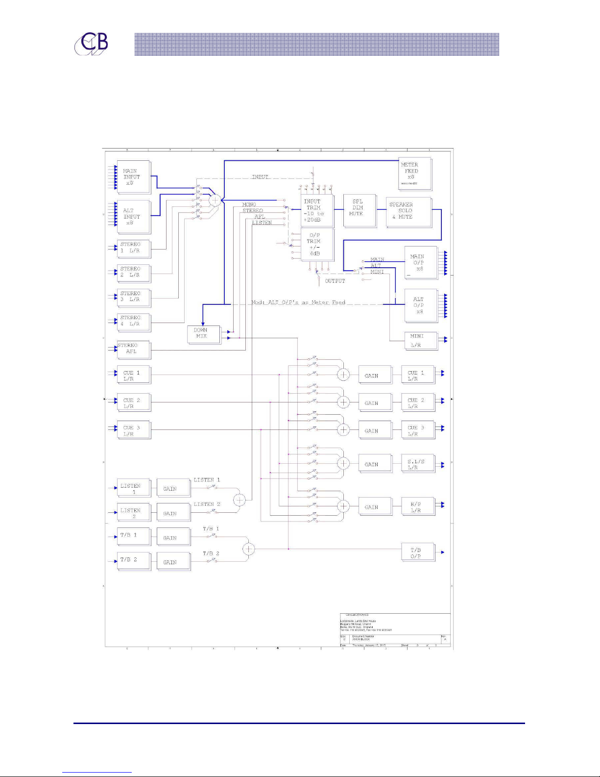
Blloocckk
B
Diiaaggrraa
D
m
m
22 June 2015 CB Electronics 47 Version 1.1
Page 53

TMC-1
Glloossssaarryy
G
Listen 1, Listen 2
Listen back channels, microphones installed in the Studio, machine room or overdub
booth which can be monitored on the control room speakers.
L/B1, L/B2, L/B 1+2
Listen back channels 1 and/or 2 are enabled
T/B 1, T/B 2, T/B 1+2
Talkback channels 1 and/or 2 are enabled,
Mono
Mono is enabled: The mono attenuator is enabled, user programmable attenuation
from 0dB to 4dB in 0.5dB steps.
SLS-A, SLS-B
Studio Loudspeaker selection A or B
There are two user keys associated with the Studio Loudspeakers SLS Mute and SLS
A/B, SLS A/B allows you to switch quickly between two Studio Loudspeaker Selections
Fn-1, Fn-2, Fn-3
Keys 9, 10, 11 originally labelled Lb, Back, Rb these are now Function Keys and will in
the future be labelled Fn1, Fn2, Fn3.
H.Mute
Hardware Mute, normal mute function and the Hardware mute GPO is active to
drive mute relays to protect your speakers and ears from digital noise and power
on/off clicks
Input and Speaker Set names
Main (Input)
Alt (Input)
22 June 2015 CB Electronics 48 Version 1.1
Page 54

TMC-1
St-1..St4
Main (Output)
Alt (Output)
Mini (output)
LFE Low
22 June 2015 CB Electronics 49 Version 1.1
 Loading...