


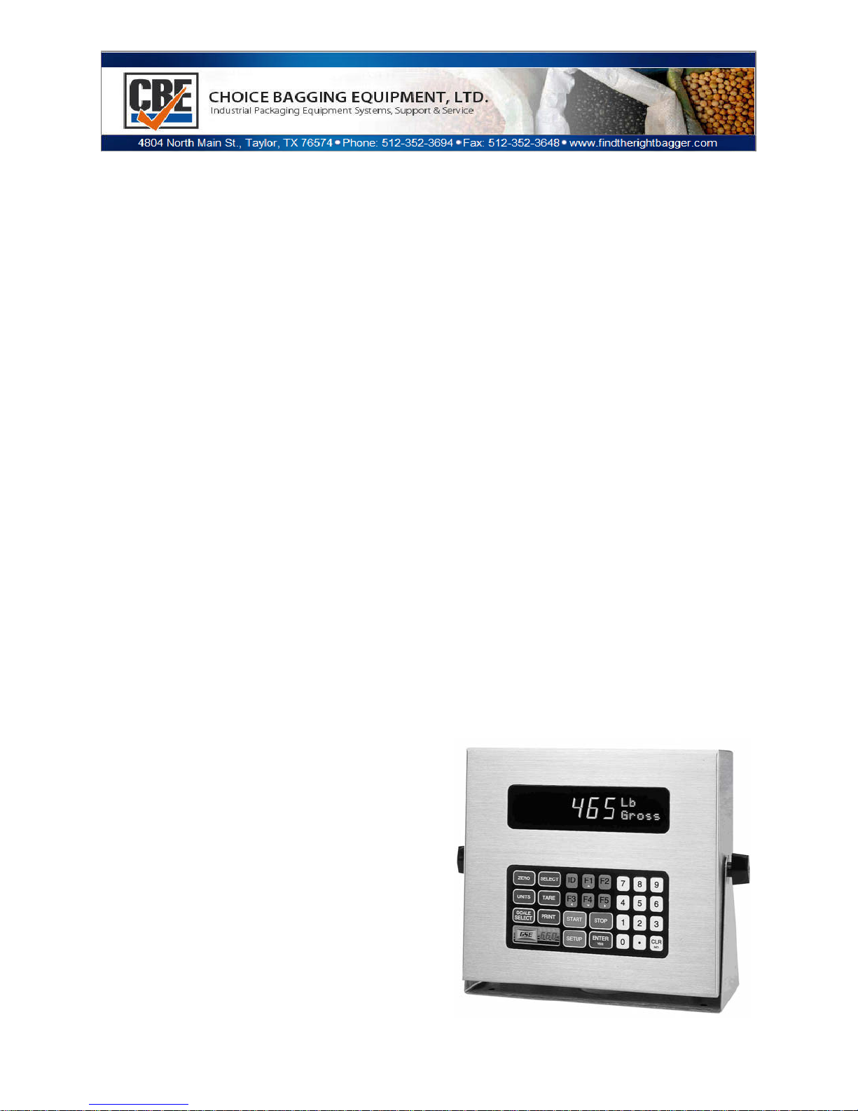
465 CONTROLLER
User’s Guide
1 OF 20

Table of Contents
SECTION 1. INTRODUCTION .................................................................................. 3
COMMON WEIGHING APPLICATIONS ........................................................ 3
CONTROLLER DESCRIPTIONS ................................................................... 4
Stainless Steel Enclosure ............................................................................... 4
FEATURES ..................................................................................................... 4
SPECIFICATIONS .......................................................................................... 5
DISPLAY ......................................................................................................... 6
KEYPAD .......................................................................................................... 7
OPTIONS ........................................................................................................ 8
SECTION 2. LEGAL FOR TRADE ............................................................................ 11
OIML AND INTERNATIONAL OPERATION ................................................... 11
NTEP ............................................................................................................... 11
Enabling NTEP Operation ............................................................................... 12
NTEP Custom Setup ....................................................................................... 12
Sealing and Audit Trails.................................................................................... 13
SECTION 3. TROUBLESHOOTING .......................................................................... 16
OPERATIONAL MODE ERROR MESSAGES ................................................ 16
SETUP MODE ERROR MESSAGES .............................................................. 17
HARDWARE PROBLEM ERROR MESSAGES .............................................. 17
CALIBRATION ERROR MESSAGES .............................................................. 19
MISCELLANEOUS MESSAGES ...................................................................... 20
SERVICE........................................................................................................... 20
2 OF 20
Section 1. Introduction
GSE 460 Series programmable indicators come standard with a number of
features that make them the most versatile and powerful systems in their price
class. Even in the most demanding industrial environments, the 460 Series
indicators will provide years of quality weighing service.
This User’s Guide contains basic operating information. Subjects covered include
indicator installation, calibration, counting mode, accumulation mode, application
file operation, the clock feature, legal-for-trade issues, and troubleshooting.
Subjects such as the Setup Mode and the macro programming language are
beyond the scope of a User’s Guide. For more detailed operating instructions, a
460 Series Technical Reference Manual is available. Contact your GSE
Distributor for more information.
Common Weighing Applications
Typical weighing applications for GSE 460 Series controllers include:
• Small parts weighing
• Large parts weighing
• Truck loading (truck in / truck out)
• Tank weighing
• Parts counting
• Process control
• Inventory control
• Order picking
• Floor and hopper scales control
• Conveyor weigh systems control
• Batching (mixing)
• Check weighing
3 OF 20

Controller Descriptions
All 460 Series models come with a swivel bracket for positioning on a tabletop or
mounting to any fixed surface.
GSE offers many options to enhance the 460 Series of indicators. The number of
options that can be used varies among the different models. See the
Specifications section on page 3 for enclosure dimensions.
Connections from the load cell to the single channel input require
gaining access to J1 inside the sealed enclosure. In addition,
peripherals and options can be interfaced to 460 Series instruments by
means of connections within the enclosure. However, physically
accessing the unit may void the warranty. Refer to the Technical
Reference Manual or contact your local GSE distributor.
Calibrating the unit requires entering the Setup Mode and selecting the
calibration parameters specific to your application needs. Contact your
local GSE distributor for calibration service.
Stainless Steel Enclosure
The stainless steel versions are also available in panel-mount.
460 Series instruments are supplied in a NEMA 4X (IP66) enclosure and may be
used in a wash-down environment. Care must be taken to ensure that the AC
power socket outlet is properly protected.
The keypad is made of silicon rubber. It may be cleaned periodically with a soft
damp non-abrasive cloth. The display window is made from a polycarbonate
material, which may scratch due to aggressive cleaning. Care must be taken to
avoid such damage.
Features
GSE 460 Series instruments share the following standard features:
• Sealed elastomer keypad for protection against harsh environments
• AC power
• DC power
• Front panel calibration and linearization execution
• Capacitive sealed keypad
4 OF 20

• Selectable weighing units: pounds, kilograms, ounces, grams, etc.
• Programmable RS-232 communications software
• Remote display support capability
• Expandable memory for increased data storage
• Battery-backed time and date clock
• Enclosure protects against water ingression
Specifications
Performance
• Full Scale Selectable
• Resolution 100,000 displayed (+/-500,000 internal)
• Display Update Selectable 0.05-20 seconds
• A/D Conversion 60 Hz
• Non-Linearity 0.005% of full scale (input dependent)
• Zero Track 0.05-20.0 displayed divisions
• Zero Range Selectable from 0.01-100% of full scale
• Calibration Selectable
• Linearization Ten multi-point calibration for linearization
• Division Size .00001 through 500
• Warranty 2 year
Electrical
• Power input 90-250 VAC, 50/60 Hz; 10-32 VDC
• Fuse 0.8 amp time lag
Load Cell Input
• Connections 4 lead or 6 lead with sense, jumper
• Power Fourteen 350-ohm cells (560 and 660 Series)
• Power Twelve 350-ohm cells (460 Series)
• Signal Range 0.1 to 20 mV/V at full scale
• Excitation 10 VDC, short circuit protected
• Current 400 mA maximum
Display
• Vacuum fluorescent, 0.75 in. high digits
• 240x64 LCD display, 5 in. x 1.34 in. usable area
• 240 x 128 LCD display, 4.72 in. x 2.52 in. usable area
• Four-line by 20-character alphanumeric display, 0.20 in. high digits
5 OF 20
• Increments 1,2, 5, 10, 20, 50, 100, 500
• Selectable decimal point
• Display values -99,999 through 999,999
• Polarity "-" sign to left of most significant active digit
• Status indicator 10-character dot matrix prompting display
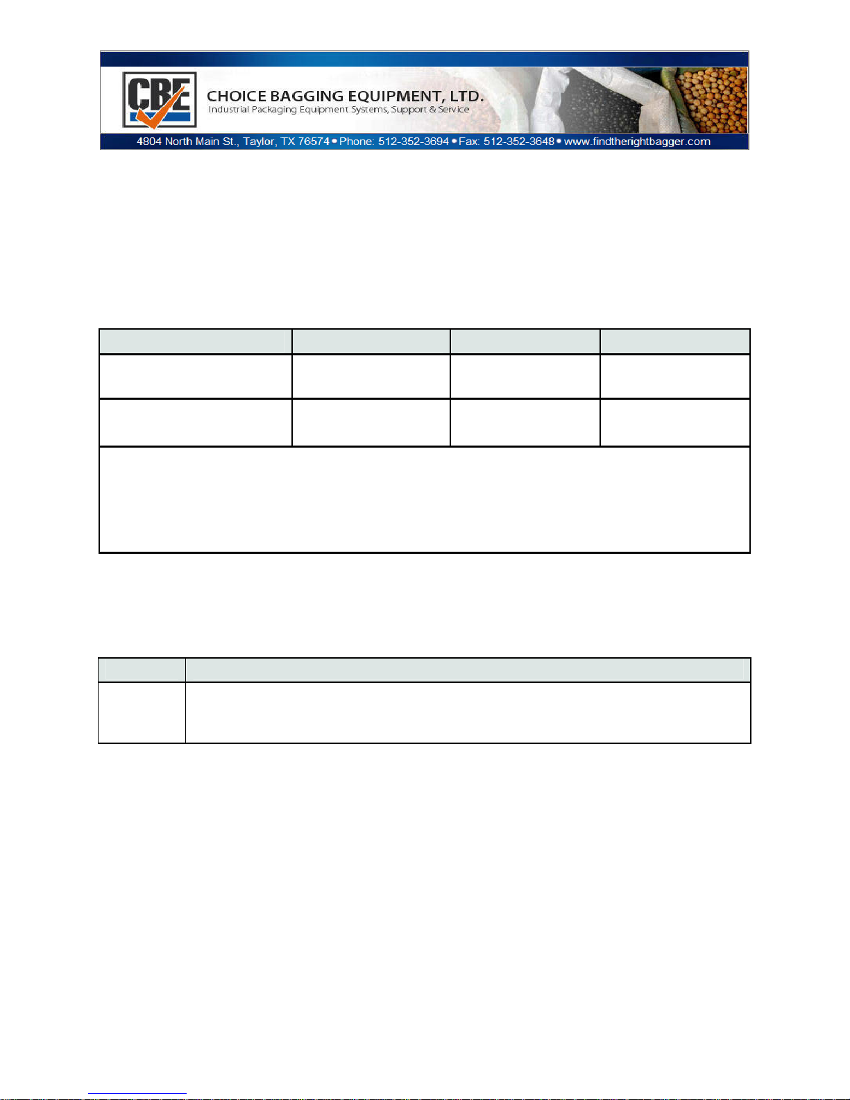
Enclosure Dimensions
Model Width Height Depth
465 Stainless Steel
11 in* (279 mm) 9 in* (228 mm) 4.4 in* (112 mm)
10 in** (254 mm) 9 in** (228 mm) 4.4 in** (112
465 Panel Mount
mm =millimeter; in =
mm)
inch *Includes
mounting stand.
**Includes mounting
flange.
Display
Display types differ according to model. The table below describes the display(s)
offered for each controller.
Model Display
465
6 digit, Vacuum Florescent display (VFD) 0.75” (19mm) height with
2X5 matrix
The vacuum fluorescent (VF) display is divided into two sections: a large, six-digit
numeric area to the left, and a smaller, two-line-by-fivecharacter dot matrix area
to the right.
The large digit area displays numeric data, such as gross weight, net weight or
tare weight.
The dot matrix area has several purposes:
• The first two characters on the upper line show the weighing units of the
displayed data.
• The last three characters on the upper line show a CENTER ZERO (-- >0<
--) condition at times.
6 OF 20

• The lower line of the dot matrix area specifies the type of data, such The
lower line of the dot matrix area specifies the type of data, such as Gross,
Net, Tare, etc.
The dot matrix area also displays specific messages during controller operation
and setup.
Keypad
A sealed elastomer keypad comes standard on all stainless steel 460 Series
indicators. For more information on the alpha keypad option, please refer to the
460 Series Technical Reference Manual. Detailed descriptions of each key and
its associated function foll ow below.
Key Description
Press [ZERO] to zero the current quantity/weight reading. When the
meter is at Center Zero center-of-zero indication will appear on the
upper line of the dot matrix display. If a Custom Unit’s name is
[ZERO]
[UNITS]
greater than 2 characters, the Center Zero indication is not
displayed. If in the quantity mode, pressing [ZERO] will set the
current mode to a gross zero quantity. If in the Weigh Mode,
pressing [ZERO] sets the current mode to Gross Weight.
Pressing [UNITS] from the Weigh Mode will toggle the displayed
units through the available selections. Converted units are
automatically rounded to the appropriate increment.
7 OF 20

[SELECT]
[TARE]
[ENTER/YES]
[PRINT] Press to send data to a printer, computer or other device.
[ID/Alpha] Used for entering ID numbers.
[F1]
[TARGET]
Pressing [SELECT] will toggle you through the Net Weight, Tare
Weight and Gross Weight or other enabled operating modes.
Pressing [TARE] by itself will perform an auto-tare. A Net Zero is
then displayed. You can enter a known Tare weight by keying in the
number and pressing [TARE]. In either case, the indicator will be
placed in the Net Mode, unless you are in the Tare Mode.
Press the [ENTER] key following certain numeric entries. Doubles
as a [YES] key for answering operator prompts.
The [F1] key is used as an up arrow key for scrolling or as a function
key (such as accessing a menu or starting a process). Not available
on Model 460.
Only available on the Model 465. Used as a function key and a down
arrow key.
Key Description
Press the numeric keys to enter numeric values 0 through 9. Press
0 - 9 & .
[CLR]
[SCALE
SELECT]
[.] to establish a decimal point or perform an accumulation in the
weigh or count mode.
Press this key to clear a numeric entry mistake prior to entering it
into memory. Also doubles as a [NO] key for answering questions.
Pressing [SCALE SELECT] will toggle through all the enabled
scale inputs.
Options
Numerous hardware options that maximize the capabilities and functions of the
standard 460 Series indicators are available. These options can be installed by
your GSE distributor at the time of purchase or be added later. All options must
be installed by a GSE distributor or a qualified technician. Please do not return
the indicator to GSE for installation of options. Consult your GSE products
distributor for installation instructions.
8 OF 20

4-Position I/O Board
460 Series supports the eight following 4-position I/O boards:
• Low Voltage AC 2 input 2 output
• High Voltage AC 2 input 2 output
• AC 4 output
• Low Voltage AC 4 input
• High Voltage AC 4 input
• DC 2 input 2 Output
• DC 4 output
• DC 4 input
16-Position I/O Board
The 16-position I/O board can be used in combination with the 4-position boards
listed above. As many as 128 I/O circuits can be configured.
Alphanumeric Serial Keyboard Converter Kit
Adapts PC keyboard to the indicator serial port (includes keyboard).
Analog Output
Up to 8 analog output cards can be added for analog output signals of each scale
value or any other independent variable. The number of available options
depends on the model of indicator.
Database
Adds capability for creating database records, consisting of fields, for data
storage and retrieval. Battery-backed SRAM increases internal storage to 256K,
1M, or 2M.
DeviceNet Module
a communication path between multiple end-points (Devices). The GSE indicator
will act as a slave on the network device layer.
Dura-Shield
A clear weatherable film lexan that adheres over the keypad and display.
Recommended when high-pressure wash-down, petroleum distillates or harsh
cleaning agents are present.
Ethernet Module
Communicate via internet or intranet connection.
Multi-Scale
Enables the use of as many as seven additional scale platforms per controller.
9 OF 20

Network Module
Addressable RS-485 network card. Full or half duplex.
Profibus Module
Allows joint operation of several systems with their distributed peripherals on one
bus. The GSE indicator acts as a slave on the network line.
RF Communication Module
Communicate wirelessly to other indicators, PC or printer.
SCR Module
DIN rail mount controller suitable for controlling AC devices such as vibratory
feeders.
Severe Transient Voltage Suppression
Protects the controller from power line transient damage.
Splash Guards
A clear flexible vinyl cover for use in harsh environments. It will keep the
indicator well protected and looking like new.
Table 1: Option Matrix
460 Series
350 Ohm load cells
Scale inputs
Setpoint I/O
Analog outputs
12
2
8
2
10 OF 20

Section 2. Legal for Trade
The 460 Series parameter setup does not ensure compliance with legal-fortrade
installations as mandated by local weights and measures authorities. This
chapter explains how to configure the 460 Series controllers to comply with
various regulations and describes other features that will make your controller
suitable for installations worldwide.
Legal-for-trade requirements vary by location. Ensure that your controller is
installed in accordance with all local regulations.
OIML and International
The International Organization of Legal Metrology is an intergovernmental body,
which harmonizes the national metrology regulations of its worldwide members.
A list of regulation publications can be obtained from the Bureau International de
Métrologie Légale (BIML) in Paris, France.
In order to configure the controller to comply with OIML requirements, P410 must
be enabled in the Setup Mode. Doing this will ensure the following:
• An over-load condition will result when the gross weight exceeds nine
graduations over the full-scale capacity.
• Full scale capacity is always referenced from the last zero calibration
reference, not the last zero acquired by pressing [ZERO
• The keypad is remapped for the international version.
• Presettable parameters will give indication that a value has been entered
manually.
Most NTEP requirements will also apply.
For detailed information on enabling OIML operation, please see the 460
Series Technical Reference Manual.
NTEP
The National Type Evaluation Program (NTEP) is a widely accepted weights and
measures standard in the United States. Most states abide by some or all of the
requirements set forth by NTEP. A complete list of these regulations is available
in the “Handbook 44” publication distributed by the National Institute of Standards
11 OF 20

and Technology (NIST). For more information on this and other NIST
publications, visit their web site at http://www.nist.gov.
Enabling NTEP Operation
In order to configure the 460 Series indicators to comply with NTEP
requirements, the NTEP parameter (P440) must be enabled in the Setup Mode.
This will have the following effects on the standard indicator’s operation:
• Pressing [TARE] with a gross weight of zero (0) or pressing 0 [TARE] will
not automatically switch to the net mode.
• Negative tare values are not accepted regardless of the selection for the
“Negative Tare Enable” parameter (P162).
• Tare values are automatically rounded regardless of the selection for the
“Tare Rounding
Enable” parameter (P163).
• Received serial data will not be processed while in the Setup Mode until
P440 is manually enabled.
• Accumulations using the [.] [ENTER] method can only be performed from
the gross, net or quantity mode.
• Printing using the [PRINT] key is only possible from the gross, net or
quantity mode.
• Weight values that exceed the minimum width specified at P240 will be
transmitted as dashes "-------".
Legal-for-trade installations using accumulations require the “number of
accumulations” parameter (9) to be accessible when not using a printer. When
using a printer, this parameter must be printed on the receipt.
NTEP Custom Setup
The “Custom Setup” parameter, P60205 of the information parameters, displays
a list of parameters, which, if configured improperly, could facilitate fraud in a
legal-for-trade installation. A weights and measures inspector might check this
parameter and inquire about the configuration of any parameters that appear in
this list.
12 OF 20

Accessing the Custom Setup List
DO NOT ATTEMPT TO ACCESS THE CUSTOM SETUP LIST DURING
CRITICAL WEIGHT PROCESSING! It is important to note that all functions of
the operating mode will be suspended immediately upon accessing the
information parameters. This includes suspension of weight conversions,
deactivation of all setpoints and cancellation of custom transmits.
The “Custom Setup” list may be accessed from the Weigh Mode. An access
code is not required to view this list.
To access the custom setup list:
1 From the Weigh Mode, key in 60205 [SELECT].
2 The Custom Setup list begins scrolling through eac h parameter to check.
If there
are no parameters to check, Std. Setup is displayed
3 The Custom Setup list may be repeated by pressing [ENTER] at P60205.
4 Press [ZERO] to return to the Weigh Mode.
A setup parameter that appears in the “Custom Setup” does not imply that it is
improperly configured. Consider the application and refer to the 460 Series
Technical Reference Manual for more details.
Additional Conformance Considerations
Several parameters must be considered on an individual basis as their
configuration may vary with different applications. Refer to the 460 Series
Technical Reference Manual for details.
Sealing and Audit Trails
Most legal-for-trade installations will require the indicator to be sealed. A sealed
indicator cannot be accessed for setup or calibration changes without breaking a
physical seal or incrementing an event counter, thus providing evidence that the
unit has been tampered with. Each member of the 460 Series has two types of
sealing provisions:
• Physical seal used in conjunction with an internal program jumper
• Three-event audit trail counter
Check with your local weights and measures authority to determine which
method(s) are required.
13 OF 20

Physical Seal
The most common sealing method is a lead-wire seal. Before applying a wire
seal, move the program jumper to the ‘NO’ position located on the indicator main
board. Refer to Table 4 for program jumper location. Doing this will prevent
access to the setup and calibration modes.
All standard units provide two tamper-proof screws used for sealing the rear
panel to the front of the enclosure. A lead-wire seal can be applied by passing
the lead-wire seal wire through a hole in these two screws, thus preventing the
screws from being removed without breaking the seal. The 460 Series panel
mount versions use a lead-wire seal and one screw.
Table 4: Main Board Jumper Location
Model(s) Program Jumper Location
460, 465 E4
14 OF 20

Audit Trail Parameters
Three separate incrementing, non-resettable audit trail parameters are used by
the M660 to indicate changes to various parameters:
• P60201 – OIML
• P60203 – Calibration
• P60204 – Setup
An audit trail counter will increment only once upon exiting the Setup Mode and
saving changes regardless of how many settings were changed. Each audit trail
counter will increment to 99999 before beginning again at 00001.
DO NOT ATTEMPT TO ACCESS AUDIT TRAIL PARAMETERS DURING
CRITICAL WEIGHT PROCESSING! Weight conversions and custom transmits
will be suspended and all setpoints will be deactivated!
Accessing Audit Trails
The audit trails may be accessed from the Weigh Mode. An access code is not
required to view audit trail parameters.
To access audit trails:
1. Key in 60201 [SELECT] to access the OIML audit trail.
2. . Key in 60203 [SELECT] to view the Calibration audit trail.
3. Key in 60204 [SELECT] to view the Setup audit trail.
4. Press [ZERO] to return to the Weigh Mode.
Calibration Audit Trail
Any changes to the existing calibration will increment the Calibration audit trail at
P60203. This includes any changes to P60101 Æ P61140 of the information
parameters.
Setup Audit Trail
Changes to any of the Setup Mode parameters will increment the Setup audit
trail at P60204.
15 OF 20

Section 3. Troubleshooting
This chapter of the User Guide provides information on error messages and
trouble-shooting 460 Series controllers. Some information in this chapter refers to
parameters that are not discussed in this guide. They are provided as a quick
reference to problems and solutions. Please refer to the technical reference
manual or consult your GSE distributor for additional information.
All 460 Series error messages are listed below in numerical order. The leading
two digits will appear on the numerical portion of the display, and the message
will appear on the two lines of dot matrix display. Following each message is a
summation of possible causes and probable remedy.
Operational Mode Error Messages
Error Description
02 UnderLoad! Input signal less than negative full scale. Check the load cell
connections. If a 4-wire load cell cable is being used, check
that the sense jumpers are in place. Verify that the capacity
selection P110 is correct. Use the information parameters,
especially P61100 to check the setup and input signal.
03 Over-Load! Input signal is greater than 104% of positive full scale. Use
same check as for underload.
04 # > Dsply Number to be displayed will not fit within 6 digits. This will not
normally occur for the Gross, Net or Tare Weights but may
result while displaying the accumulated totals if the amount
exceeds 999,999. Clear the totals or settle for only being able
to transmit the totals.
05 Zero> Max.! An attempt was made to zero out more than allowed per P118
selection. Use the [TARE] key for subtracting off container
weights or if large dead load is always to be present, apply
this dead load during the New Zero? prompt during calibration
to eliminate the offset.
06 Tare>F.S.! Tare entry was greater than full scale. Most likely the entered
tare value was incorrect.
16 OF 20

07 Tare < 0 ! Negative tare attempted, but not allowed per P162. For auto-
tares, the GROSS Weight must be greater than zero unless
P162 is changed to allow negative tares.
08 CheckConn. Displayed if the signal into the A/D is +/- 2 times the Full Scale
signal. This is effectively taken into consideration when the
information sent to the microprocessor from the A/D is +/twice the allowable F.S. reading. ie. P110 F.S. = 100. Error
message will be displayed at +/- 208 taking into consideration
the 4% overload.
Setup Mode Error Messages
Error Description
10 Entry>Max! An entry was made which had more characters than allowed.
11 WRONGCODE! The incorrect access code was entered, thus preventing
changes. In order to access the Setup Mode, either the
proper code must be entered or [ENTER] must be pressed
alone (to view selections without making changes).
12 No Mods! The Setup Mode is being accessed, but changes are
prevented.
13 OutOfRange An entry made for a selection was beyond the range of valid
choices.
14 Must Keyin The choice for the current parameter must be keyed in.
15 Size>3999! The size of a Custom Transmit setup has exceeded the limit.
16 CHECK JUMPR A programming operation was attempted when the program
jumper is installed. Installation of this jumper prohibits
programming changes.
Hardware Problem Error Messages
Error Description
17 A/D BAD! The processor has detected a problem with the A/D chip.
17 OF 20

Contact your GSE distributor.
18 BufSzMax! The accumulative total buffer size for both the TX and RX
buffers of all four COMM ports is 4096 bytes. Displayed If
entries to the “buffer size” parameters (P207-P208) exceed
this total.
19 x06\x44\x61ta&Stop Certain combinations of protocol are not available. The
protocol combination selections are in P201, P202 and P203.
This error occurs if an illegal protocol combination is selected.
Refer to the Communications chapter in the technical
reference manual.
20 Deflt A/D This message appears for 1 second. It will be displayed if the
A/D calibration data gets corrupted. Contact your GSE
distributor.
21 WriteNVErr Error reading data from the EEPROM. Possible U16 and U17
problem.
22 ReadNVErr Error writing data to the EEPROM. Possible U16 and U17
problem.
23 CheckNVPar Supplementary error message for above errors.
24 NVParFull! The setup being attempted requires more EEPROM than is
currently installed.
Error Description
25 DefltSetup Upon power-up the indicator has not found the proper codes.
Therefore all parameters have been reset to factory default
values.
26 Bad Setup The stored data has a checksum error. Check all parameters
or re-load setup.
27 RE-BOOT! The indicator cannot use the EEPROM for data storage, so it
is attempting to power-up again to cure the problem.
18 OF 20

28 NoRAMAVAIL The current setup requires more RAM than is currently
installed. Contact your dealer or the manufacturer.
2
29 PIN error This message will appear on power-up or setup if the E
2
corrupted in the PIN section. Check E
for problems. The
is
access code is defaulted to the manufacturer (GSE) access
code. Also check Error 11.
Calibration Error Messages
Error Description
30 F.S.>MAX!
The entered calibration weight, together with the currently applied
signal, indicates that the full scale signal will be greater than the
allowed maximum of the indicator. Verify that correct entries have
been made for the capacity, P110, and for the calibration weight.
If all appears correct, refer to the use of the information parameter
P61100, and determine the output (in mv / volt) of the connected
load cell.
31 F.S.<.1mVv
32 ADD MORE!
33 ReCALReq'd
34 RES> 25K!
The entered calibration weight, together with the currently applied
signal, indicates that the full scale signal will be less than the
allowed minimum of the indicator. Verify the proper entries for the
capacity, P110, and for the calibration weight. If all appears
correct, refer to the use of the information parameter, P61100 and
determine the output (in mv / volt) of the connected load cell. The
applied weight during calibration was less than 0.1% of capacity.
More weight than this is required. Refer to P61100 if this is
incorrect.
The just completed calibration may not yield accurate results due
to either the cal weight being less than 5% of capacity or this was
the first calibration of this platform to this indicator and therefore
the coarse gain was adjusted by the indicator.
The current combination of capacity P110 and increment P111
result in a resolution greater than 25,000 graduations. This is
simply a warning in case this was not intended.
Error Description
35 RES>100K! The current combination of capacity P110 and increment P111
result in a resolution greater than 100,000 graduations. This
19 OF 20

is not allowed and as soon as any key is pressed the
instrument will jump back into the Setup Mode to parameter
P110 to verify the settings.
36 RES< 100! The current combination of capacity P110 and increment P111
result in a resolution less than 100 graduations. This is simply
a warning in case this was not intended.
37 RES< 1!! The current combination of capacity P110 and increment P111
result in a resolution less than 1 graduation (i.e. the increment
is greater than capacity). This is not allowed and as soon as
any key is pressed the instrument will jump back into the
Setup Mode to parameter P110 to verify the settings.
Miscellaneous Messages
Error Description
EntryError This error message is the most commonly used. The primary
causes are entering a value preceding a key (such as
[ZERO]) which is not allowed, entering alpha data for a
numeric selection, or entering a fractional value for an entry
which only accepts whole numbers. Occurs in Setup Mode or
an operational mode
WhichTx#? The instrument is setup with more than one custom transmit
with parameter P991 set for Prmpt (Prompt) and the [PRINT]
key is pressed. The WhichTx#? message is asking for a
custom transmit number to be entered. Key in the custom
transmit, then press [ENTER]. i.e. [2] [ENTER], for custom
transmit number 2.
.
Service
There are no user-serviceable items in the GSE 60 Series. Service must be
performed by a qualified service technician only. Attempts to service this
instrument by unqualified personnel may void the warranty
20 OF 20
 Loading...