

Page 1

Customer Name
Project#: INPAK SYSTEMS/CERTIS USA
Customer PO#: 0130369-3
Serial#: 140726
Model: 230 Auger Packer/ Certis USA Project
Controller: Avery ZM405
Electrical Controls: 220/440/ other_
Electrical Motors:
Air Requirements:
Special Features: CLASS 2, Division 2, Group 2 Electrical
230 Series Auger Packer
1 OF 115
Page 2
CBE 230 AUGER PACKER
Safety - Installation - Operation - Maintenance
_________________________________________________________________
230 Series Auger Packer
2 OF 115
Page 3

Table of Contents
FOREWARD ...................................................................................................................................................................... 5
IMPORTANT NOTICE ..................................................................................................................................................... 5
WARNINGS ....................................................................................................................................................................... 6
BEFORE OPERATING EQUIPMENT: ........................................................................................................................... 6
WHEN OPERATING EQUIPMENT: .............................................................................................................................. 6
ELECTRICAL NOISE CONSIDERATIONS .................................................................................................................. 9
BACKGROUND NOISE ................................................................................................................................................... 9
EFFECTS OF ELECTRICAL NOISE .............................................................................................................................. 9
GROUNDING RECOMMENDATIONS ...................................................................................................................... 10
AC POWER CONSIDERATIONS ................................................................................................................................. 10
RECOMMENDED 230 SPARE PARTS LIST .......................................................................................................................... 11
CHAPTER 1 ........................................................................................................................................................................ 12
RECEIPT AND INSPECTION ....................................................................................................................................... 13
ASSEMBLY PROCEDURES ......................................................................................................................................... 13
SOLENOIDS / PNEUMATICS ....................................................................................................................................... 14
SUPPLY BIN CONNECTIONS...................................................................................................................................... 14
CHAPTER 2 ........................................................................................................................................................................ 15
INSTALLATION PROCEDURES ................................................................................................................................. 16
PNEUMATIC CONNECTIONS ..................................................................................................................................... 16
ELECTRICAL CONNECTIONS ................................................................................................................................... 16
FINALIZATION OF INSTALLATION ...................................................................................................................................... 17
CHAPTER 3 ........................................................................................................................................................................ 18
PRINCIPLE OF OPERATION ........................................................................................................................................ 19
SEQUENCE OF OPERATION ....................................................................................................................................... 19
PHASE ONE ..................................................................................................................................................................... 19
PHASE TWO .................................................................................................................................................................... 20
CHAPTER 4 ........................................................................................................................................................................ 21
MAIN FRAME ASSEMBLY .......................................................................................................................................... 22
FRONT POST ASSEMBLY............................................................................................................................................ 22
AUGER SCREW DRIVE TUBE ASSEMBLY ............................................................................................................. 22
AUGER MOTOR ............................................................................................................................................................. 22
BELT DRIVE ASSEMBLY ............................................................................................................................................ 22
FEED SYSTEM ASSEMBLY ........................................................................................................................................ 22
AUGER BARREL HOUSING ........................................................................................................................................ 23
AUGER SEAL ASSEMBLY........................................................................................................................................... 23
INLET HOPPER ASSEMBLY ....................................................................................................................................... 24
HOPPER SEAL ASSEMBLY ......................................................................................................................................... 24
BELT GUARD ASSEMBLY .......................................................................................................................................... 24
BAG CLAMP ASSEMBLY ............................................................................................................................................ 24
INFLATABLE VALVE BAG SEAL .............................................................................................................................. 24
BAG CHAIR ASSEMBLY .............................................................................................................................................. 24
DUST COLLECTOR ASSEMBLY ................................................................................................................................ 25
PNEUMATIC CONTROLS ............................................................................................................................................ 25
ELECTRICAL CONTROL ............................................................................................................................................. 25
ATTACHMENTS AND OPTIONAL FEATURES ...................................................................................................... 26
230 Series Auger Packer
3 OF 115
Page 4

CHAPTER 5 ........................................................................................................................................................................ 27
PNEUMATIC ADJUSTMENTS .................................................................................................................................... 28
MAIN LINE PRESSURE ................................................................................................................................................ 28
BAG SEAL REGULATOR ............................................................................................................................................. 29
POWERED BAG CHAIR FLOW CONTROLS ........................................................................................................... 29
AIR PURGE STUFFING BOX PRESSURE ................................................................................................................. 29
MECHANICAL ADJUSTMENTS ................................................................................................................................. 30
AUGER 30
BAG CHAIR POSITION ................................................................................................................................................. 31
MOTOVIBRATOR BAG CHAIR SETTLER POSITION ........................................................................................... 31
MAINTENANCE, LUBRICATION, & ADJUSTMENTS TO MOTOVIBRATOR ................................................ 32
INTENSITY OF THE VIBRATOR ................................................................................................................................ 32
NOISE LEVEL ................................................................................................................................................................. 32
MAINTENANCE ............................................................................................................................................................. 33
LUBRICATION ............................................................................................................................................................... 33
CHAPTER 6 ........................................................................................................................................................................ 34
NON-INFLUENCING SPOUT ....................................................................................................................................... 35
COMPONENTS OF A NON-INFLUENCING SPOUT ............................................................................................... 35
CHANGING THE ISOLATOR SEAL ON AN EXISTING NON-INFLUENCING SPOUT ASSEMBLY ............ 36
DETAILED LAYOUT OF COMPONENTS OF THE ASSEMBLY ........................................................................... 37
CHAPTER 7 ........................................................................................................................................................................ 38
PLC & TIMER ADJUSTMENTS ................................................................................................................................... 39
PLC SCREEN ................................................................................................................................................................... 39
ADJUSTING THE TIMER ............................................................................................................................................. 39
PLC ........................................................................................................................................................................... 40
INPUT/OUTPUT SCREEN ............................................................................................................................................ 40
VIBRATORY/DENSIFIER ON DELAY ...................................................................................................................... 40
CHAPTER 8 ........................................................................................................................................................................ 41
GENERAL MAINTENANCE ........................................................................................................................................ 42
MAINTENACE GUIDE .................................................................................................................................................. 43
MAINTENANCE TIPS ................................................................................................................................................... 46
CHAPTER 9 ........................................................................................................................................................................ 47
GENERAL TROUBLESHOOTING .............................................................................................................................. 48
TROUBLESHOOTING GUIDE ..................................................................................................................................... 48
ILLUSTRATED PARTS ................................................................................................................................................... 53
CHAPTER 10 ...................................................................................................................................................................... 67
465 CONTROLLER USER’S GUIDE .......................................................................... ERROR! BOOKMARK NOT DEFINED.
SCHEMATICS & DRAWINGS .................................................................................................................................... 109
GENERAL ARRANGEMENT DRAWING................................................................................................................ 112
230 Series Auger Packer
4 OF 115
Page 5

FOREWARD
This manual has been prepared to assist you with your Choice Bagging Equipment, Ltd. bag packaging
equipment.
The text contains instructions for installation and operation of your packing equipment, as well as
directions for adjustment and maintenance.
Following the text is the reference section which contains drawings; bills of materials, recommended
spare parts, manufacturers' bulletins and any other information necessary to the successful operation of
your equipment.
If further information or assistance is needed, please contact us at:
Choice Bagging Equipment, Ltd.
4804 North Main Street, Taylor, TX. 76574
Phone: (512) 352-3694, Fax: (512) 352-3648
Parts Email: INFO@choicebagging.com
Equipment Website: www.choicebagging.com
IMPORTANT NOTICE
READ THIS MANUAL COMPLETELY before installing, starting-up, or operating this equipment. Be
certain all personnel concerned with this machinery are fully alerted to the possible HAZARDS of the
equipment and its utilities (electrical and pneumatic) before any operation is allowed.
Choice Bagging Equipment, Ltd. cannot emphasize enough the importance of good safety practices in the
use of this equipment.
Sound engineering and design practices have been applied to minimize the possibility of accidents.
However, while using equipment of this type, good judgment and extreme caution are necessary on the
part of all personnel.
The purpose of this section is to alert operating and maintenance personnel to the possible dangers of
this type of equipment. Serious injury and/or equipment damage could result from not heeding these
safety precautions.
If any clarification is required -- ASK US.
230 Series Auger Packer
5 OF 115
Page 6

WARNINGS
The purpose of this section is to alert operating and maintenance personnel to the possible dangers of
this type of equipment. Serious injury and/or equipment damage could result from not heeding these
safety precautions.
BEFORE OPERATING EQUIPMENT:
Any personnel working directly with or on this equipment should read this manual before proceeding
with equipment use.
Electricians should familiarize themselves with the electrical drawings before initial start-up of
equipment.
Other appropriate operating and maintenance personnel should familiarize themselves with mechanical
layout and general arrangement drawings before setting up and doing start-up on equipment.
Determine location of all emergency switches.
Be sure all guards are in place and observe all warning signs.
Be sure electrical equipment is free of any accumulation of water.
Be sure all personnel are clear of operating mechanisms before connecting air line.
Never start equipment without first checking for loose objects, tools and trash. All persons in the
immediate area of the equipment should be alerted prior to starting.
WHEN OPERATING EQUIPMENT:
Observe extreme caution when switches are turned on. On some equipment, the operation may begin
automatically after a time delay.
Do not open junction boxes or control panels unless you are a qualified electrician. Be sure power is off.
Except when electricians are performing maintenance, electrical enclosures and junction boxes should
always be securely closed.
Stop machine and disconnect power before servicing or repairing. Follow all LOCK OUT / TAG OUT
PROCEDURES when performing maintenance and adjustments on this equipment. A disconnect is
provided that has a place for LOCKOUT.
230 Series Auger Packer
6 OF 115
Page 7

Do not attempt to defeat any safety switches. Serious injury could result.
While machine control power is on, do not activate limit switches manually. Serious injury and/or
machine damage could result. Disable machine before attempting any maintenance or manual testing of
components.
Motors will get warm to the touch and should not cause concern for equipment reliability and operation.
A temperature rise is normal per new NEMA specifications.
If additional wire runs are added to any junction box or control panel, wiring practice should be such as
to maintain prevailing electrical hazard classification.
High-pressure air systems are dangerous. Do not service or troubleshoot systems with air supply on. Be
sure to bleed off any trapped air before working on components since it is possible to have high
pressures trapped in airlines and cylinders, etc.
Keep fingers, hands, feet, etc. out of path of pneumatically operated components.
Safety glasses should be worn in equipment area.
Follow the safety regulations for your plant. ALWAYS USE GOOD JUDGEMENT!
230 Series Auger Packer
7 OF 115
Page 8

WITHIN THE TEXT OF THIS MANUAL:
"WARNING" indicates possible injury to personnel.
"CAUTION" indicates possible damage to equipment.
"NOTE" is an informational comment.
Before you begin production AND as you continue working daily with the machine, these points should
be observed for continuous service. Service parts such as belts, stuffing box material, bearings, gears, fill
spouts, etc. are available for replacement and stock supplies through Choice Bagging Equipment.
230 Series Auger Packer
8 OF 115
Page 9

ELECTRICAL NOISE CONSIDERATIONS
A major consideration in the installation of a successful system is the problem created by electrical noise.
The following paragraphs provide information to help the user avoid electrical noise problems. Though
many potential problems are presented, few, if any, will be encountered in an actual application using a
suitably installed PLC system, even in a relatively harsh industrial noise environment.
BACKGROUND NOISE
Electrical noise is defined as any unwanted electrical signal which enters the control equipment. Noise
signals cover the entire spectrum of frequencies and may have any wave shape. The largest single
difficulty with noise is that it is not always present. Continuous, or frequent, periodic noises are generally
easy to detect and accommodate. Intermittent noise sources that produce short, high energy bursts at
irregular and widely spaced intervals cause the majority of problems. Noise has a number of different
pathways into the control equipment. It can be conducted through signal or power wiring or it can be
radiated by electromagnetic waves. Conducted noise is typically coupled into the signal or power wiring
either electro-statically or magnetically. Electrostatic coupling occurs through parasitic capacitance
between the noisy line and the signal/power line. This typically would be the case for long wire runs in
the same conduit. Magnetic coupling occurs through parasitic mutual inductances between lines. This
requires high currents or high currents or high rate of change of current as well as significant mutual
inductance, which may result from proximity or wiring. Electromagnetically radiated noise is typically
high frequency (radio waves). The control system and its wiring may act as antennas in picking up noise
signals. This pathway is least likely to present problem levels of noise to a PLC, and its sources are rare
industrial applications. The dominate sources of noise in industry are those devises (and their wiring)
that produce and switch high voltages and currents. Typical examples include large motors, welders, and
contactors that switch heavily inductive loads such as brakes or clutches. Other examples of noise
sources are Triac/SCR motor control and power invertors.
EFFECTS OF ELECTRICAL NOISE
The predominant effect of noise on the system is to cause “soft” failures; that is, failures which do not
damage the system but do cause it to function improperly.
Three main types of soft failures are encountered:
Logic memory alteration.
Register alteration.
Momentary I/O failure.
Logic memory alteration presents the most significant potential problem in that it may, in some cases,
result in improper machine operation. Both register and momentary I/O failures normally result only in
nuisance failures such as operation in the wrong mode, machine glitches or incorrect/non-existent error
messages.
230 Series Auger Packer
9 OF 115
Page 10

GROUNDING RECOMMENDATIONS
A good grounding system is a major consideration in planning any electrical system. However, it is
essential for proper operation of the electronics that a low-impedance path to earth ground exist. All
filtering devices internal to the PLC require a good earth ground return. The structural ground present in
many industrial environments does not provide an adequate ground return. A supplementary grounding
electrode should be used to reduce the impedance of the earth ground return when direct-wire
connection to the power system is not feasible. As a minimum, a No. 12 AWG stranded copper wire
should be used to connect to the copper grounding electrode. The connection should exhibit very low DC
resistance (0.05 OHM) and low high-frequency impedance (such as copper lugs). Minimum wire sizes,
color coding, and general safety practices should comply with American National Standards and the
National Electrical Code.
Other earth ground sources are not as desirable as a copper ground stake. Green wire earth grounds
(safety grounds) brought into the control system from plants distribution networks tend to be very noisy.
In most plants, the green wire earth ground system is characterized by ground loops, multiple
terminations to different references, and long wire runs adjacent to motor power and other high-power
wiring. Conduit as an earth ground has even more problems. Though many installations use these
ground references successfully, the practice should be avoided.
AC POWER CONSIDERATIONS
Electrical devices should not be operated at the low end of their input power voltage rating for extended
periods of time. When input voltage is low, current input is forced higher to provide the devise with the
power of needs. Additional current means additional heating. When a system is to be installed where
long brownouts are known to occur, the user is advised to supply the PLC with power from a voltage
regulating transformer. Use of this type of transformer will provide normal voltage to the devices and
keep current within normal range.
230 Series Auger Packer
10 OF 115
Page 11

RECOMMENDED 230 SPARE PARTS LIST
QTY
Description
Part Number
1
LOAD CELL
104-009
1
SOLENOID VALVE
105-020
1
SOLENOID VALVE ADAPTER
105-020A
1
SOLENOID CONNECTOR CORD FOR AC
105-049
1
SOLENOID CONNECTOR CORD FOR DC
1050409
1
BAG CLAMP CYLINDER
101-001
1
BAG CLAMP TIP
119724
1
ROD EYE
104-038
2
FLEXURE PLATE
101-010
1
RELAY BOARD FOR 465
104-041
1
ON/OFF SWITCH
109-209
1
PUSH BUTTON, GREEN
109-207
1
PUSH BUTTON, RED
109-208
1
E-STOP, CLOWN NOSE
109-052
1
VALVE, PILOT
145301
OPTIONAL
1
VALVE SEAT, 12” BLACK (Optional)
145460
OPTIONAL
1
VALVE SEAT, 12” WHITE(Optional)
145466W
OPTIONAL
1
ACTUATOR
OPTIONAL
1
Agitator, Spike MS
1
Agitator, Paddle MS
1
Agitator, Paddle, SS
1
Agitator, Spike SS
1
AUGER PER APPLICATION
1
NOZZLE PER APPLICATION
4
DUST SLEEVES
PER APPLICATION
1
DROP DOOR- PROX
1
Switch, Door cleanout
201-008
1
HINGE DOOR SAFETY SWITCH
109-096
2
BEARINGS - 4 HOLE FLANGE
EPS-2080
1
VFD - 240 volt (voltage specific)
PER APPLICATION
1
VFD – 480 volt (voltage specific )
PER APPLICATION
1
VALVE, PILOT BAG SEAL
145301
OPTIONAL
1
AIR PURGE STUFFING BOX (Auger)
3#
STUFFING (Buy the pound)
H-120
1
CONTACTOR , MOTOR
109-010
AGITATOR
1
OVERLOAD
109-111
AGITATOR
1
CYLINDER, BAG CHAIR
184379H
OPTIONAL
1
CYLINDER , BAG CHAIR REPAIR KIT
186567H
OPTIONAL
1
VALVE, SHUTTLE
111-001
OPTIONAL
1
VALVE, CHECK
20473
OPTIONAL
1
SWITCH, AUTO START
111-001
OPTIONAL
4
BUSHING, BAG CHAIR (SHORT)
5081-01-181
OPTIONAL
2
BUSHING, BAG CHAIR, (LONG)
5081-01-1913
OPTIONAL
4
ISOLATOR SEAL
Non-influencing spout Per application
OPTIONAL
1
CONTACTOR, MOTOR
AUGER
1
OVERLOAD AUGER
230 Series Auger Packer
11 OF 115
Page 12
OF EQUIPMENT
CHAPTER 1
RECEIPT
230 Series Auger Packer
12 OF 115
Page 13

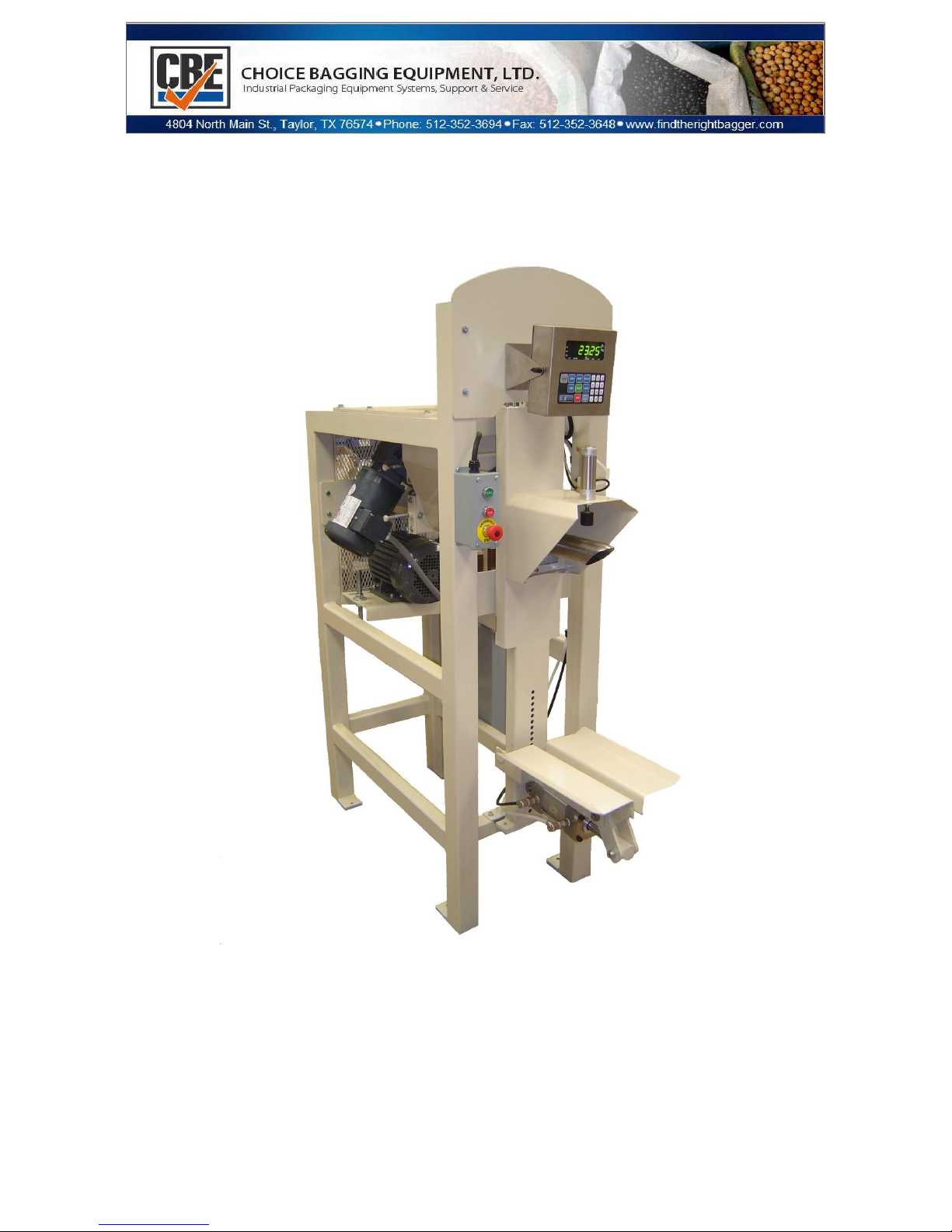
The Model 230 Auger Packer consists of the packer
assembly and various items as ordered.
RECEIPT AND INSPECTION
Upon receipt, a check should be made to see that all
items ordered have arrived and are in good condition.
Any damage incurred in shipment should be reported to
the delivering carrier immediately and a claim for the
damage should be filled. If anything is missing or
damaged, contact Choice Bagging Equipment, Ltd. (512352-3694) so that replacement or repair can be initiated.
The Model 230 Auger Packer is shipped with locking
bolts installed to secure and protect the bag post and
weighing assembly during shipment. (See Picture)
ASSEMBLY PROCEDURES
Mark the centerlines of the packer, reference the General Arrangement drawing.
Set the packer into place. It may be desirable to defer final anchoring to the floor until after testing. Place
the packer in the proper location, insuring the frame is level. Check the clearance and fit to the feed
hopper and associated piping prior to securing it firmly to the floor.
It is recommended to install a rubber connection sleeve between bin and
hopper to isolate bin vibrations from packers. (Sleeve not provided with
machine. Recommend 0.25” - 0.375” wall thickness. Sleeve can be
purchased from CBE separately).
The weighing assembly is secured by two shipping bolts that protect the
scale from any damage during shipment. Be sure to remove the shipping
bolts located above the bag chair post before attempting to operate the
machine.
The Model 230 Auger packer uses a load cell scale weighing unit. It is
important to make certain that the load cell and components being
suspended are free from side friction.
Check the alignment of the fill tube to the auger. If adjustments need to
be made to the auger, this is discussed later in Chapter , how to adjust
230 Series Auger Packer
13 OF 115
Page 14

the auger.
SOLENOIDS / PNEUMATICS
All pneumatic components (air valves & cylinders) are self-lubricating and additional lubricated air is not
required. If lubricated air is used then lubricated air must be used for the life of all the cylinders.
It is recommended that the main high pressure airline supplying the packer be a min size of ½”. Connect
this high-pressure airline to the regulator found on the back side of thee packer. If there are multiple
units, it is recommended to have separate lines feeding each packer. Operating pressure should be 80PSI
It is recommended that an additional water trap (not supplied with machine) be installed up stream of
the packer in the high-pressure airline and the packer. This is to ensure clean dry air is coming to the
machine at all times. We have recommended that the water trap have a self-draining tap.
Any optional equipment ordered when the packer is in the field will be shipped with controls, hose and
fittings. These will need to be installed in the field according to the pneumatic schematic provided. If the
machine was ordered from the factory with option equipment, this will already be done. There is room
for only one addition optional feature to be added in the field at a later date.
Connect all air hoses which were disconnected for shipment. All hoses and related fittings are
correspondingly color coded and size related for ease of re-assembly. All hoses on the packer are: white
for start and black for stop.
Install any attachments which have been shipped loose or separate from the packer. The connection
between the packer inlet the mating supply hopper should be made using a soft flexible connection to
minimize the transmission of vibration.
NOTE: Auger Packers are relatively trouble free as far as basis operation stands. Problems may occur
with the controller or electrical system. If problems occur do not hesitate to call us for information at
(512) 352-3694.
SUPPLY BIN CONNECTIONS
It is recommended that you connect the packer to the supply hopper or surge bin with a rubber
connector. This will minimize or eliminate any vibrations coming from the bin that may influence the
weight.
These collars and bands are available from Choice Bagging Equipment; however they are not supplied
with the equipment. If you would like to order, you may reach our parts department at 512-352-3694.
230 Series Auger Packer
14 OF 115
Page 15
INSTALLATION
CHAPTER 2
230 Series Auger Packer
15 OF 115
Page 16

INSTALLATION PROCEDURES
Your system was assembled and tested in our factory. At disassembly, decals with match markings were
applied on matching parts to facilitate installation. Study the General Arrangement and other subassembly drawings to determine the location of items. The center point of the packer inlet must be
located and marked on the floor; accomplish this by suspending a plumb bob from the center of the
mating supply hopper overhead. Verify that this center point on the floor is the proper distance from the
centerline of any associated equipment. Once this match has been verified, the packer can be put into
place and leveled.
NOTE: Do not anchor any equipment to the floor at this time. Equipment should be anchored to the floor
only after a satisfactory alignment and start-up has been achieved. Care must be taken in leveling the
packer at this point. After the packer has been placed in the desired operating location, level the packer
by plumbing the front legs. Any deviation from the plumb between the two legs should be compromised
half-way. This will result in plumb center lines. This step is important for the scale to function properly.
PNEUMATIC CONNECTIONS
Control air for the system should be supplied from a high pressure air source and should be clean and
dry. A minimum of 80 PSIG pressure at approximately 3-5 SCFM is required for proper operation of the
system. Air line connections must be ½” or larger. All air line connections should be made using a flexible
hose to minimize the transmission of vibration. Connect the pneumatic lines using the pneumatic
schematic and the color coded end connections.
ELECTRICAL CONNECTIONS
Control power for the system should be supplied from a clean power source and voltage verified to
ensure proper operation of the system.
NOTE: All wiring is to be accomplished in accordance with national electric code requirements. All
electrical connections should be made using a flexible type conduit to minimize the transmission of
vibration.
CAUTION: When drilling holes for conduit, make sure that absolutely no drill chips enter the panel, as
they may create a short circuit in the control circuits. Check all terminal block connections. Tighten those
which may have come loose during shipment. Connect all sensor and motor wires per the electrical
schematic and the color coded end connections. Terminations from the main electrical control panel to
junction boxes may be required per the electrical schematic. Connect the weighing system’s load cell
cable per the electrical schematic.
NOTE: To avoid the effects of electrical noise on the weighing system, avoid routing load cell cables near
any high voltage source.
230 Series Auger Packer
16 OF 115
Page 17

FINALIZATION OF INSTALLATION
Check all wiring connections with either an ohm meter or a buzz to verify continuity of all wires.
Check all led proxy switch lights (power).
Wiring and wire runs should be installed as not to interfere with equipment operation and in accordance
with appropriate electrical code.
Make a rotational check of all motors. If phases are reversed, this can be corrected by changing two
power wires in the motor junction box.
All gear reducers are sealed. They are factory sealed to ensure proper operating temperature and
prolonged life.
Check air pressure at all regulators and set per the pneumatic schematic.
(OPTIONAL) Fill all the air lubricator reservoirs if equipped. All cylinders and solenoids don’t require
lubrication).
230 Series Auger Packer
17 OF 115
Page 18
CHAPTER 3
OPERATION
230 Series Auger Packer
18 OF 115
Page 19

PRINCIPLE OF OPERATION
An auger feed assembly is the main feature of the Model 230 Auger Packer. The auger housing receives
bulk product from a surge bin and supplies a steady stream into the bag utilizing a flighted auger screw.
High-pressure air (80 PSIG), operates the solenoids and cylinders.
Bags are weighed during the filling operation on a unit consisting of bag support frame and filling tube
mounted on the front of a scale beam. Filled bags are discharged automatically when the machine is
equipped with an automatic discharge bag chair arrangement.
All of the operation activity for each bag filling cycle takes place in a matter of seconds. This packing
speed is important, not only to achieve high production rates and bag accuracy, but also for proper
function of the Model 200 Auger Packer
SEQUENCE OF OPERATION
A representative arrangement of the packer is shown below. It serves to amplify the following
description of a typical; TWO PHASE operational sequence for filling a bag. It should be noted, however,
that a variety of constructions are optional for the Model 200. The sequences as drawn shows the
optional timed powered discharge and timed bag sealer.
PHASE ONE
(Bulk and Dribble)
Phase One is the condition the machine is in at the end of a filling cycle or if the Stop (or scale)
pushbutton is pressed. This is what occurs:
Controller reaches final preset target weight.
The motor drive assembly and agitator stop and the auger reverses.
The material from the product surge bin stops flowing into the packer.
The bag clamp releases the bag.
The bag is discharged from the machine (hand or automatic). Since the material is moved by gravity
flow, the supply of material to the machine is continuous.
Various optional features shown on the schematic operate as follows:
The valve sealer deflates at end of filling cycle - this can be timed to ensure material stabilization in the
bag.
230 Series Auger Packer
19 OF 115
Page 20

Feed gate closes off the material flow inlet hopper when the goes into the dribble mode (used with
products that flow easy and may flood)
The settler stops if running in continuous mode. (No bulk and dribble)
The powered discharge bag chair tilts to discharge the filled bag at the end of the sealer deflation and
returns.
The speed of these features is controlled with special electrical and pneumatic controls. During Phase
One, the operator also places another empty bag on the filling tube after discharge of the previous bag.
PHASE TWO
Phase Two is the condition the machine is in at the beginning of a filling cycle or if the (Start or Auto
Start) pushbutton is pressed. This is what occurs:
The start PB is pressed.
The bag clamps the empty bag to the fill spout
The bag seal inflates inside the valve of the bag (Optional)
The motor drive (auger) and the agitator start to turn.
A delay and then the settler turns on (Optional)
Material starts to flow into the bag and is weighed simultaneously as it is being filled
Weight reaches first set point.
Settler turns off.
Auger and agitator continue to run but go from fast to slow fill.
Weight reaches second set point (final cutoff).
Phase one note:
If machine is equipped with a bulk only feature the auger will never go into a slow speed. It
will continue at the fast speed all the way thru the entire filling cycle.
230 Series Auger Packer
20 OF 115
Page 21
CHAPTER 4
COMPONENT
DESCRIPTION
230 Series Auger Packer
21 OF 115
Page 22

The CBE 230 Consists of the Following Assemblies:
MAIN FRAME ASSEMBLY
The main frame assembly consists of a rigid steel frame and a hinged motor base plate.
The motor base plate has threaded rod adjustment to allow for V-belt tensioning and the hinge side of the
motor base is adjustable to accommodate a wide range of motor sizes.
FRONT POST ASSEMBLY
The front post is the weighing mechanism on which the bag and product is supported during the filling
process. The front post is mounted to the main frame by one S-Type load cells and two spring steel
flexures. The load cell detects changes in the deflection and sends a varying low voltage signal to the
weight controller. The signal is then interpreted by the weight controller to determine when the desired
cut-off weight is reached.
AUGER SCREW DRIVE TUBE ASSEMBLY
The auger screw drive tube assembly unitizes the mounting of the auger support bearing to allow for
quick removal and re-installation of the auger without disturbing the placement of the bearings, sheaves
or drive belts. The delivery auger is supported by two self-centering flange bearings which can be
adjusted to provide proper auger alignment.
AUGER MOTOR
The delivery auger is powered by a 5 H.P. TEFC motor and the agitator is powered by a 1 HP TEFC
MOTOR.. This machine also features a plug reverse action of the auger at the end of each filling cycle. This
feature provides an immediate cut-off of product flow when the desired cut-off weight is reached and
withdraws excessive product from the spout to reduce spillage when the filled bag is removed. This
motor is specially designed to minimize heat generated during frequent start/stop/reverse duty cycles.
BELT DRIVE ASSEMBLY
The belt drive assembly consists of two v type belts and sheaves to transmit power from the auger motor
to the auger. These components were selected for their low rotational inertia, consistent with proper
power transmission from the motor to the auger. A variety of sheave combinations allows selection of
the optimum auger speed for the product being packed.
FEED SYSTEM ASSEMBLY
The feed system consists of; delivery auger, agitator and spout assembly. The auger delivers product
from the auger barrel housing, through the spout, and into the bag being filled. The agitator keeps the
230 Series Auger Packer
22 OF 115
Page 23

material moving downward toward the feed auger. All augers are balanced and checked before leaving
the factory. Care should be taken to be sure that the auger is not bent or dropped during installation,
cleaning or servicing of the packer. The physical characteristics of products are especially important to
consider when two or more products are to be packaged on the same machine. If the physical
characteristics of the products vary greatly, it may be necessary to have a different auger for each
product for best results. There are two different style spouts that packers can be equipped with: Live
spout and a non-influencing spout. The non-influencing style spout assembly consists of a cone and
integral inner spout which is mounted to the auger barrel housing, and an outer spout which is mounted
to the front post. Since the outer spout is mounted on the front post it is not influenced by the material as
it comes thru the inner spout. The cone and inner spout provide a means to move product from the
auger barrel housing section to the bag, while the outer spout is weighing the product as it is being
discharged into the bag without the material touching the scale (outer spout). A flexible seal is provided
as the connection between the inner and outer spouts to accomplish this and this seal prevents product
from getting between the spouts. Note: If material gets between the two spouts it can cause an influence
to the weighing system. A movable tapered sleeve/cone is also provided to seal the valve during the
filling process to minimize dust. Correct adjustment of the tapered sleeve is important. When the bag
seals onto this tapered sleeve, the internal bag sleeve must be approximately 1” back from the mouth, or
bottom edge, of the spout. Feed systems can be manufactured in a wide variety of sizes, types, finishes,
and materials to fit a particular application.
AUGER BARREL HOUSING
The auger barrel housing receives product from the inlet hopper and houses the rear section of the
delivery auger. The auger barrel can be manufactured in a wide variety of finishes and materials to fit
any application.
AUGER SEAL ASSEMBLY
There are two types of auger seal assemblies which are used to prevent the escape of product from the
rear of the auger barrel. The stuffing box type and air seal type. The most commonly used is the stuffing
box type which utilizes compression shoes and either lamb’s wool or Teflon packing material. Teflon
packing is typically used for food grade applications. The stuffing box is efficient, provided the wool or
Teflon packing is clean. Abrasive particles of product under pressure from the packing glands can cause
severe wear to the auger shaft. For this reason it is recommended that the wool or Teflon be inspected
periodically, and replaced if necessary. The air auger seal utilizes air. Air is used between the seals, and
air is injected between the seals into the auger barrel. Since the air cannot escape past the seals, it slowly
bleeds into the auger barrel. This creates a positive pressure into the auger barrel, therefore preventing
the escape of product. (Regulator should be set at 2-3 PSI)
230 Series Auger Packer
23 OF 115
Page 24

INLET HOPPER ASSEMBLY
There are several types of inlet hopper assemblies which are used to receive and pre-condition product
from the main supply hopper. There are “V” hoppers, spike and ribbon style agitator hoppers. The “V”
hopper does not contain any agitators and is used to simply transition from the main supply hopper to
the auger barrel. This type of hopper is used for free-flowing products only. The agitator hopper contains
a single agitator to pre-condition the product prior to the auger barrel and delivery auger. This type of
hopper is used for products with slight to moderate bridging characteristics. The agitator is powered by a
shaft mounted gearbox driven by its own motor. All hoppers can be equipped with an access door with
access door safety switch to provide maintenance/clean out access. Inlet hoppers can be manufactured
in a wide variety of finishes and materials to fit a particular application.
HOPPER SEAL ASSEMBLY
There are two types of hopper seal assemblies which are used to prevent the escape of product from the
RA-5 agitator shaft. The waste packing box type and the air seal type are used on the agitator hopper as
well as the auger seal assembly.
BELT GUARD ASSEMBLY
A belt guard assembly is provided to cover the auger drives. These guards should always be fully
installed when the packer is in use. If it is necessary to service the V-belts, the rear guard may be opened,
however there is a safety switch which shuts the packer down totally.
BAG CLAMP ASSEMBLY
There are several types of bag clamp assemblies which may be used to secure the bag during the filling
process. The most common of which are either manual or air operated. Manual valve bag clamps are a
simple over-center clamping devise requiring operator actuation prior to starting the filling cycle. Air
operated clamps, however, are actuated automatically whenever the filling cycle is requested.
INFLATABLE VALVE BAG SEAL
This seal is an inflatable rubber boot that is put on the outer fill spout and inflates and deflates with each
filling cycle. This seal is used primarily for dust control situations.
BAG CHAIR ASSEMBLY
There are several types of bag chair assemblies which may be used to support the bag during the filling
process. The most common of which are either manual or air operated, and can be vibrating or nonvibrating. Manual bag chairs simply support the bag during the filling process and pivot forward to assist
in manual removal of the filled bag. Air operated bag chairs are actuated automatically upon completion
of the filling cycle and are used to discharge the filled bag lengthwise across the take-away conveyor. The
vibratory bag settlers are used to settle and distribute product in the bag during the filling process. Both
230 Series Auger Packer
24 OF 115
Page 25

models utilize a pair of motor driven counter weights which alternately raise and lower the bag support
pads. In addition to the typical valve bag chairs, open mouth bag and drum/box filling roller racks are
available. These attachments may also be either vibrating or non-vibrating. The vibrating roller racks
utilize a piston type vibrator to settle and distribute product in the bag during the filling process.
DUST COLLECTOR ASSEMBLY
A dust collection shroud and 4” round diameter pick-up connection is provided to help control the dust
emissions which may be generated during the filling process. Ensure that this connection is made using a
flexible type hose to minimize the transmission of vibration.
PNEUMATIC CONTROLS
The main system regulators should be set so that air pressure does not exceed 80 PSI. Plant air systems
are not adequately filtered; therefore a filter/regulator is installed before all components to assure clean
air. This is necessary for smooth-acting, longer lasting components. Moisture collecting in the bottom of
the filter bowl should be bled off as often as necessary. The screens should be cleaned or replaced every
960 hours of operation.
Watch for air leaks around fittings and flexible hoses. Proper pressure and volume are necessary for this
machine to operate correctly. A variety of solenoids and/or air piloted valves are used throughout the
pneumatic system to control the various air operated components as required.
ELECTRICAL CONTROL
The electrical consists of two assemblies: the drive motor starter panel and weight controller. Refer to
the electrical drawings provided in this manual for wiring details. In addition to the drive motor, motor
starter and weight controller, a variety of limit switches, proximity switches, etc. may be used throughout
the system to control various functions as required.
230 Series Auger Packer
25 OF 115
Page 26

ATTACHMENTS AND OPTIONAL FEATURES
Various Attachments and features can be added to this machine. They include the following:
Open mouth attachment for filling open mouth bags
Drum and box attachment.
Non-influencing spout
Drop bottom hinged door for cleanout.
Bag chair settler
Tilting bag chair settler for automatic discharge
Valve bag sealer for better dust control
12” feed gate to prevent flooding thru the auger
Air seal stuffing boxes
Auger quick change feed system
Auto Start switch- will start the fill cycle when the bag is placed on the filling spout
Drop door for easy cleanout
BA Dust Hood
Casters
230 Series Auger Packer
26 OF 115
Page 27
Startup Instructions
& Adjustments
CHAPTER 5
230 Series Auger Packer
27 OF 115
Page 28

The CBE 230 is an automatic packer. The operator is required to put an empty bag on the filling spout
and press the Start push button after the empty bag is in place. The Start, Stop and E-Stop Push Button
enclosure is located on the front of the packer.
The bag is then filled and weighed automatically, and when equipped with powered bag chair, is
discharged automatically.
If for any reason it is desired to interrupt the filling operation in the middle of a cycle, a red Stop
pushbutton is provided located directly underneath the green Start push button.
Depending on the style controller being used, pressing the Stop once will pause the filling process and
pressing the Stop twice, will abort the fill process.
It is recommended that the following adjustments be made to the packer before any material is delivered
to the receiving hopper:
Make sure all personnel are clear of machine.
Pneumatic Control System
Open manual valve for incoming high-pressure air.
Adjust pressure regulator to 80 PSIG (with power off).
Electrical control system is on.
Voltage coming in matches the sticker on the outside of the box.
Should your packer be equipped with a VFD, please be aware that VFD’s are voltage specific; if voltages
do not match, it will burn the VFD out.
PNEUMATIC ADJUSTMENTS
MAIN LINE PRESSURE
A minimum of 80 PSI should be maintained on the filter regulator at all times during normal operation.
Air pressure can be adjusted by a large hand knob at the top of the regulator. There is also a ¼ turn
needle valve at the bottom of the regulator underneath the water trap bowl. This devise serves to
separate some of the water out of your supply air before allowing it to enter into the bag filler. DRY AIR
IS REQUIRED FOR PROPER OPERATION OF THIS EQUIPMENT. THIS REGULATOR WILL NOT
SEPARATE ALL WATER FROM YOUR AIR SUPPLY. Special care and consideration should be made to
ensure that the compressed air being delivered to the filler is clean and dry. Drain and clean weekly or
230 Series Auger Packer
28 OF 115
Page 29

daily if necessary depending on the humidity of your environment. If excessive contamination and water
accumulate in the transparent bowl, it should be cleaned more often.
BAG SEAL REGULATOR
Place an empty bag on the filling tube. Press the Start pushbutton.
Adjust THE BAG SEAL REGULATOR PRESSURE TO 3-5 PSIG. This regulator is normally located on the
front leg left side. The gauge on the regulator only goes from 0-15 PSI. From the factory, they are
normally set very low, 1-2 PSI as to prevent damage to the rubber boot if started without a bag on the fill
spout. The seal should expand just enough to secure the valve to the fill spout. Excessive pressure will
damage/crack the valve sleeve and could damage the bag seal.
Caution: Never start the packer without a bag on the fill spout with the bag seal pressure.
Always have an empty bag on the spout. Damage could and will occur to the bag seal if over
inflated without an empty bag on the spout.
POWERED BAG CHAIR FLOW CONTROLS
Flow controls are located right on the cylinder of the bag chair. Take a 3/16” blade screwdriver and
insert into the slot of the flow control. Turning clockwise will slow the motion of the cylinder down.
When adjusting the motion of the cylinder always adjust at the opposite end of the cylinder from where
the action is occurring at.
AIR PURGE STUFFING BOX PRESSURE
On the air purge stuffing box, there are controls. There is a pilot valve and a regulator. The regulated
pressure should be 0-5 PSI. If excessive air is used you will fluidize your product and you may have a
hard time getting it into the bag.
230 Series Auger Packer
29 OF 115
Page 30

MECHANICAL ADJUSTMENTS
AUGER
WARNING: SHUT OFF ELECTRICAL POWER AND LOCK OUT BEFORE NEXT OPERATION
CAN BE DONE SAFELY.
The auger should not rub on the fill spout at any time. If auger is found not to be centered in the fill spout
and it is rubbing the fill spout, proceed as follow:
Shut off electrical power to machine and lock out
Check which way the auger has to move to get the auger centered in fill spout
Go to the rear of the packer and do as follows:
Loosen motor and remove belts
Take two ¾” wrenches and loosen four ½” bolts
Move bearing to make correct adjustment to the auger in fill spout
When the auger is aligned, put the bearings back together
Re-install all belts
Re-tighten motor
Adjust the position of the filling tube cutoff assembly so that it is centered around the auger with equal
clearance on all sides.
230 Series Auger Packer
30 OF 115
Page 31

Pasted Bags:
Place a bag on the filling tube and smooth the body of the bag down. Unfold the
bottom of the bag to a horizontal position. Position the bag chair so that it touches the
bag.
Sewn Bags:
Place a bag on the filling tube and smooth the body of the bag down. For first setting,
position the bottom of the bag chair s1ot 1 " be 1ow the bottom of the bag.
BAG CHAIR POSITION
Bag chair is raised and lowered manually to adjust to bag length. A series of holes in the bag post accepts
a pin on the bottom of the chair assembly, resulting in a secure setting.
Because of the wide variety of valve bags available, trial and error experimentation may be required to
obtain the optimum bag chair adjustment. Correct adjustment is best made with a filled bag.
Prior to removing the filled bag from the filling spout, verify that the weight of the bag is resting on the
bag chair and not hanging from the packer spout. The paper (or plastic) at the top of the bag should not
be under tension.
Incorrect bag chair adjustment is a common cause of off weight and bag size problems. Care should be
taken that the bag chair position is high enough to allow the bag to fill out properly at the end of the filling
cycle, especially in the upper portion of the bag. If the chair is not high enough, the bag capacity may be
greatly reduced.
CAUTION: Improper use of the bag chair can cause damage to the weigh beam. Do not
drop, stand or jump on the bag chair.
MOTOVIBRATOR BAG CHAIR SETTLER POSITION
On units featuring the motovibrator settler function, the settler can be run in different modes. They are:
Continuously through the entire fill cycle – In this mode in the PLC has a timer that can be adjusted as
when to start. This is to allow time for material to get into the bag before starting to settle .This is the
most common setup.
Settling during the Bulk Cycle only – In this mode the controller has to have bulk and dribble feature.
When the bulk set point (setpoint 1) is reached the settler will stop and drop down.
230 Series Auger Packer
31 OF 115
Page 32

MAINTENANCE, LUBRICATION, & ADJUSTMENTS TO MOTOVIBRATOR
WARNING: The Motovibrator must be serviced by qualified personnel.
Disconnect the power supply to the motovibrator during disassembly and re-assembly operations on the
protection devices (earth and terminal board covers), checking current absorbed.
Remove the terminal board cover, power the motovibrator, and use ammeter pliers on all the phases to
ensure that the current absorbed does not exceed the value on the rating plate. If this is not the case,
ensure that the frame or flexible structure on which the motovibrator is positioned conforms to the
correct rules for application. Never touch the motovibrator when it is operating. Never start the
motovibrator without the protective covers on the earth and terminal boards. After a brief period of
operation, again check the elements fixing the motovibrator to the frame.
INTENSITY OF THE VIBRATOR
WARNING: The operation must be carried out only by a qualified technician, with the
power supply disconnected.
Remove the side covers after unscrewing the bolts.
Loosen the main bolt, shift the movable weight (or the lamellar weight) to the required position and
tighten the bolt again after fitting the respective washers. The weights must be adjusted so as to be
perfectly equal and in the same direction on both sides. Refit the covers, after replacing the OR sealing
ring without damaging it. N.B.: ALL STANDAR MOTOVIBRATORS ARE SUPPLIED WITH THE WEIGHTS
ADJUSTED TO THE MAXIMUM.
NOISE LEVEL
The weighted equivalent continuous noise level of the motovibrators is NEVER higher than 76 dB(A)*.
*measurement made in normal operating conditions in accordance with standard ISO 6081/86, with
simulated load consisting of a steel bench fitted on springs. It is, however, COMPULSORY for the
manufacturer of the machinery on which the motovibrator is fitted to measure the final noise levels on
the finished machinery or plant. It is also COMPULSORY for the employer to measure the noise levels in
the work area where the machinery or system with the motovibrator is installed. These measurements
must be done before starting up the plant. It is also compulsory to use suitable devices for personal
protection and train operators as specified by L.D. 626.
230 Series Auger Packer
32 OF 115
Page 33

APART FROM WHAT HAS BEEN SPECIFIED ABOVE, IT IS NECESSARY TO RESPECT THE REGULATIONS
APPLICABLE IN THE COUNTRY IN WHICH THE MACHINE IS OPERATED.
MAINTENANCE
WARNING: Maintenance must be performed ONLY by qualified technicians, with the
power supply disconnected.
CAUTION: Before starting operation, ensure that the temperature of the motovibrator is
not higher than 40ºC.
LUBRICATION
All the motovibrators are initially lubricated by the manufacturer. Motovibrators which employ ball
bearings (pre-lubricated and shielded) do not require lubrication. Models with roller bearings require
grease replacement only after 3000 hours of operation. Use KLÜBER STABURAGS NBU 8 EP grease. For
disassembling and cleaning the bearings, refer to the paragraph below. Do not mix different types of
grease even if they have similar features. An excessive amount of grease may overheat the bearings and
thus damage them.
230 Series Auger Packer
33 OF 115
Page 34

Non-Influencing
CHAPTER 6
Fill Spout
230 Series Auger Packer
34 OF 115
Page 35

NON-INFLUENCING SPOUT
This design consists of a spout within a spout. This is to isolate the scale system from the feed coming
thru the fill spout.
It is used with materials that tend to build up or cake on the inside surface of the fill spout. This build-up
in a single wall spout would cause restriction on scale movement and cause weight variance.
WARNING: Only qualified technicians should perform maintenance on the noninfluencing spout.
Disconnect the power supply to the 200 Auger Flow during disassembly and reassembly of the non-influencing fill spout. Maintenance should NEVER be
performed with electrical power connected to the machine.
COMPONENTS OF A NON-INFLUENCING SPOUT
Outer Spout Tip
Wire retainer
Outer spout
Inner spout
Inner Spout retainer ring
Isolator seal
230 Series Auger Packer
35 OF 115
Page 36

CHANGING THE ISOLATOR SEAL ON AN EXISTING NON-INFLUENCING SPOUT ASSEMBLY
Locate the out spout tip wire retainer
When you find the wire retainer, take a pliers and pull wire completely out
Now remove the outer tip by turning back and forth gently and pulling at the same time to remover tip.
Locate the nuts to take the outer spout off and remove 4 nuts, removing outer spout.
Locate the wire retainer in the inner spout retainer ring.
Remove inner spout retainer wire completely
Slide the inner spout retainer ring back just so it clears the seal and remove old isolator seal.
Install new seal on inner spout
Put liquid hand soap on your finger and run your finger all the way around the back edge of the new
inner seal, to help the inner ring slides up over the seal easier.
Slide the inner retainer ring back in position aligning up the wire groove on the ring and the inner spout.
Put a few drops of soap in the groove and take a new retainer wire and start it in the groove.
Install retainer wire in until you see it coming out the other side. Stop pushing the wire in and pull back til
wire disappears on the other side.
Clip the wire as close as you can on this side.
Take your pliers or a pointy tool and push the end you just clipped off back in under the retainer ring.
There should be no wire exposed.
Reinstall outer spout with 4 nuts (do not tighten- just snug)
Check the alignment between the two spouts. You must verify that the spouts are centered on each other
and that there is clearance all the way around them. Once you believe you have them aligned you may
ensure proper clearance by taking a wire to the gap between them and running it all the way around.
This will ensure there is sufficient clearance.
If you don’t have clearance and need to adjust the spout, try to move the outer spout. If the nuts are too
tight, loosen the 4 nuts, just enough that you can move it. Move it the direction required and retighten
nuts. Recheck alignment and redo until you have clearance.
Once proper clearance between the two spouts has been established, take the seal and roll it over onto
the outer spout.
230 Series Auger Packer
36 OF 115
Page 37

Put a little liquid soap on the outer part of the seal and install outer tip aligning the wire groove.
Install retainer wire in groove, as you did for the inner spout, clipping off excess wire so there is no wire
exposed.
This completes the installation.
See drawing detail “A” of the spout tip.
DETAILED LAYOUT OF COMPONENTS OF THE ASSEMBLY
3. Outer spout
4. Inner ring
5. Isolator seal
6. Outer retainer wire
7. Inner retainer wire
230 Series Auger Packer
37 OF 115
Page 38

PLC & TIMER
ADJUSTMENTS
CHAPTER 7
230 Series Auger Packer
38 OF 115
Page 39

PLC & TIMER ADJUSTMENTS
PLC means Programmable Logical Controller. Our PLC is programmed with specific programs to work
with our equipment. Our programs are set up for Valve filling, O/M net weigh and gross weighing
equipment.
The PLC has several timers relating to specific functions. There are different programs for various types
of equipment. The PLC is programmed at the factory with default settings but they need to be fined tuned
in the field. Below we discuss how to adjust the timers what they operate.
PLC SCREEN
Name of the levels and timers
1-Choice Bagging Equipment ( CBE )
2- Feed gate (toggle) Normal gate operation or closes when the packer goes into the dribble mode
3- Reverse
4. Bag Clamp Delay
5. Input / Output Screen illuminations
ADJUSTING THE TIMER
Use the A or B button to Scroll forward or backward through the Timers.
Once you reached the desired time press the OK key. (The timer is able to be edited when the selected
time flashes in a solid block. The timer cannot be edited when the numbers remain solid and flashes
white.)
Use the + and – keys to adjust the timer up and down in 0.1 second increments.
When done press the OK key again and numbers will be solid and flash white.
Press the Escape key to return to menu and using the up / down arrows scrolling back to the CBE screen.
230 Series Auger Packer
39 OF 115
Page 40

PLC
Feed Gate (Output 3) Factory default setting 0.0 (Must Choose Mode) toggle
This function opens and closes the feed gate.
Normal gate operation Mode– the gate will stay open the entire fill cycle and close at the end of the filling
cycle. Delay would be on opening.
Gate opens during Fast (Bulk) fill only- closes when the packer goes into the dribble mode. Delay would
be on opening.
Bag Chair (output 5) Factory Default setting .9
This timer is used where the equipment is equipped with a powered discharge chair. The chair will
remain up for the length of time the timer is set for.
Reverse (output 6) Factory default setting: with a VFD 1.4 sec, w/o VFD .9 sec
This is the time the auger will turn in reverse at the end of the fill cycle.
Bag clamp (Output 4) Factory default setting 1.5
This is the time the bag clamp remains clamped to the fill spout not letting go of the bag. This timer can be
used also to add time to allow the bag to settle/ de aerate so the material does not spill out of the bag
INPUT/OUTPUT SCREEN
The PLC screen displays which inputs and outputs are signaling on and off at any point during the bag
filling process. They are “on” when they are gray color or lite.
Bag chair timer (output 5)
VIBRATORY/DENSIFIER ON DELAY
This is a separate timer not found in the PLC that selective Modes and time ranges. This timer is set on
the on-delay timer function. The on delay function is used to allow material to get into the bag, before the
bag densification system comes on. It is adjusted in second increments. Factory setting is 10 seconds.
This function is used to help densify the material in the bag as it is filling.
230 Series Auger Packer
40 OF 115
Page 41

MAINTENANCE
CHAPTER 8
230 Series Auger Packer
41 OF 115
Page 42

WARNING: Maintenance must be performed ONLY by qualified technicians, with the
power supply disconnected.
GENERAL MAINTENANCE
The CBE 230 is designed to be operated and maintained by the user. It is suggested that operation and
maintenance personnel study and thoroughly understand the function and working relationship of each
part before any adjustment, maintenance, or troubleshooting is performed. The following
recommendations are based on general observations made in our factory and at various installations.
These recommendations may need to be adapted to suit your operating conditions. For this reason, we
recommend you keep a detailed log recording all maintenance, adjustments, replaced parts and
malfunctions. These records will assist in several ways; they will show which parts most often have to be
worked on or replaced. The log should be reviewed weekly and used to set up a preventative
maintenance program. Keeping the system clean and well lubricated is most important to insure
maximum performance and service life of the equipment. Lubrication charts and maintenance guides
are provided on the following pages for your assistance. Only qualified maintenance personnel should
work on this equipment. Before attempting any maintenance be sure to read the Important Notice
section at the beginning of this manual regarding safety precautions.
WARNING: Always disconnect electrical and pneumatic utilities when servicing
related components.
For equipment not manufactured by Choice Bagging Equipment, Ltd see appropriate Manufacturer’s
Bulletin.
230 Series Auger Packer
42 OF 115
Page 43

MAINTENACE GUIDE
We have broken the machine down in to assemblies and listed the recommended maintenance for each.
The following should be performed at regular intervals.
FRONT POST ASSEMBLY
LOAD CELLS
Check load check leakage for free movement. Adjust as required.
Check for loose bolts. Tighten or replace as required.
FLEXURES
Ensure that the flexure is not bent and/or out of level. If the flexures are out of level binding
will occur between them and cause the bag weights to be erratic. Level the upper flexure
and then measure the distance from the upper to the lower on both the front and back to
make sure they are the same. If not the same loosen the front bolt that go thru the bag post
and adjust the flexure up or down to obtain the same dimension between them.
Check for loose or missing bolts. Tighten as required.
BEAING BASE ASSEMBLY
BEARINGS
Check the bearing seals for deterioration and/or leaking grease. Grease or replace as
required.
Check for excessive vibration with the auger running. If rubbing is taking place then the
auger may need to be realigned in the fill spout. (See chapter on how to center filling spout
in fill tube.)
AUGER MOTOR
BEARINGS
Check the shaft seals for deterioration and/or leaking grease. Replace as required.
BELT DRIVE ASSEMBLY
V-BELTS
Check for proper belt tension. ½” deflection is required. Adjust as required.
Check for deterioration and/or cracking. Replace as required.
SHEAVES
Check for excessive wear. Replace as required.
Check alignment. Align as required, top sheave to button.
230 Series Auger Packer
43 OF 115
Page 44

FEED SYSTEM ASSEMBLY
AUGER
Check that the auger is centered in the spout. (See chapter on how to center filling spout)
Check that the auger is not bent. Straighten or replace as required.
SPOUT
Check for proper alignment of the spout and cone. Re-align as required using the load cell
and adjusting the flexure plates.
Check the flexible seals for deterioration, bulging and/or cracking. R/R as required
Remove any product build-up.
AUGER SEAL ASSEMBLY
PACKING
Check stuffing box for leakage and adjust for proper compression. Adjust when box is
leaking.
Check packing material for cleanliness. Replace as required.
AIR SEAL
Check the shaft seals for deterioration and/or cracking and proper pressure on regulator.
Pressure on mini regulator should be 2-3 PSI. Adjust air pressure flow and if still leaking
replace seal.
INLET HOPPER ASSEMBLY
BEARINGS
Check the bearing seals for deterioration and/or leaking grease. Grease or replace as
required.
Check for excessive vibration with the agitator running. Replace as required.
HOPPER SEAL ASSEMBLY
PACKING
Check for proper packing compression. If leaking, adjust compression or replace packing.
Check packing material for cleanliness. Replace as required.
BAG CLAMP ASSEMBLY
PIVOTS
Check for excessive wear. Replace as required.
PADS
Check for excessive wear. Replace as required.
Check for excessive pressure on the spout. Adjust as required.
230 Series Auger Packer
44 OF 115
Page 45

BAG CHAIR ASSEMBLY
PIVOTS
Check for excessive wear. Grease or replace as required.
SETTLER
Check for excessive vibration. Check to see if rubber isolator rubber.
PNEUMATIC
FILTERS
Check for dirty filter elements. Clean or replace as required.
Check for moisture accumulation. Drain as required.
REGULATORS
Check regulators for proper pressure setting. Adjust as required.
LUBRICATORS
Check lubricator oil level. Fill as required.
Check lubricator flow rate. Adjust as required.
CYLINDERS
Check the piston rod end seals for deterioration/cracking. Replace as required.
Check the piston rod for excessive wear. Replace as required.
Check rod end cushions for smooth operation. Adjust as required.
Check for loose or missing mounting hardware. Tighten or replace as required.
HOSES
Check all hoses for deterioration and/or cracking. Replace as required.
Check for leaks around fittings, valves, seals, etc. Tighten or seal as required.
ELECTRICAL
PHOTO EYES
Clean all photo eyes and reflectors.
Check alignment of photo eyes and reflectors. Adjust as required
LIMIT SWITCHES
Check alignment of limit switches and actuators. Adjust as required.
PROXIMITY SWITCHES
Check alignment of proximity switches and actuators. Adjust as required.
JUNCTION BOXES
Check for loose/broken wires or components. Tighten or replace as required.
Blow off any excessive build-up of product/dust.
Make sure all J-Boxes are closed when not being worked on.
Control Panels
230 Series Auger Packer
45 OF 115
Page 46

Check for loose/broken wires or components. Tighten or replace as required.
Blow off any excessive build-up of product/dust.
Make sure all enclosures are tightly closed when not being worked on.
MAINTENANCE TIPS
Check on a regular basis the isolator rubber tubing for wear or bulging.
Check the belts for fraying, checks and the bearings for deterioration.
Grease the bearings at least one a week or as needed per environment.
STUFFING BOX
The stuffing box should be checked for leakage. To order new stuffing the part number is H-120. To
replace stuffing, remove the stuffing box end caps and take out the old, dirty stuffing. Pack the box with
new, clean stuffing. Using a hammer and blunt tool, pound the stuffing material solidly into the stuffing
box and fill completely. Repeat the process until the box is completely filled. Replace end caps tightly.
As the auger is in operation, check the stuffing box. The jam nuts should be tightened back to hold the
stuffing inside. If material is seeping out the stuffing box, continue to tighten the bolt pressing the ear in
harder until the seepage stops. It is not necessary daily, but should be checked to make sure material is
not leaking out the box.
AUGER
Check auger frequently for smooth operation. Check to see if it is warped or bent. Movement, noise or
vibrations are indications of problems.
230 Series Auger Packer
46 OF 115
Page 47

TROUBLESHOOTING
CHAPTER 9
230 Series Auger Packer
47 OF 115
Page 48

GENERAL TROUBLESHOOTING
All packers are designed so that they can be operated and maintained by the user. It is suggested that
operation and maintenance personnel study and thoroughly understand the function and working
relationship of each part before any adjustment, maintenance, or troubleshooting is performed.
The following pages are Troubleshooting Guides to assist you in determining causes of malfunctions in
your system and the action required to rectify the condition.
Prior to using this troubleshooting section, check for loose or broken wires, binding part, etc., which may
be the cause of the problem. Keeping the system clean and well lubricated is most important to insure
maximum performance and service life of the equipment. Lubrication charts and maintenance guides
are provided on the following pages for your assistance
Only qualified maintenance personnel should work on this equipment. Before attempting any
maintenance, please read the Important Notice section at the beginning of this manual regarding safety
precautions.
WARNING: Always disconnect electrical and pneumatic utilities when servicing related components. For
equipment not manufactured by Choice Bagging Equipment, Ltd., see the appropriate Manufacturer’s
Bulletin.
TROUBLESHOOTING GUIDE
Issue: Weight Variations
Possible cause: Bag chair position not correct
Because of the wide variety of valve bags available, the bag rest adjustment should best be done by trial
and error. Correct adjustment can best be made with a filled bag. Prior to removing the filled bag from
the filling spout, verify that the weight of the bag is resting on the bag saddle and not hanging from the
packer spout. The paper at the top of the bag should not be under tension.
Incorrect bag saddle adjustment is a common cause of off-weight and bag size problems. Care should be
taken that the bag saddle position is high enough to allow the bag to fill out properly at the end of the
filling cycle, especially in the upper portion of the bag. If the saddle is not high enough, the bag capacity
may be greatly reduced.
Possible cause: Bag size too small
A frequent source of off-weight trouble is under-size bags. The bags should never be excessively filled,
since this causes the product in the spout to be compressed. The spout is part of the scale system and
must be free to move up and down about the auger. The compression of the product in the spout will
restrict the freedom of motion of the scale system and will cause off-weight bags. If off-weights occur,
and it appears that the packer is functioning properly, it is suggested that the bag size be checked, as
230 Series Auger Packer
48 OF 115
Page 49

outlined below. Set the packer scale to stop filling at 80% of the desired bag weight. Fill several bags at
the reduced capacity and check weights. If weights are good, gradually increase the set weight until the
weights again become erratic. If it is determined that the bag is too small, consult the bag supplier for
help in selecting a bag of the proper size.
Possible cause: Vibration
Check for vibration which may be transmitted to the weighing system from possible sources such as
loose or worn V-belts, dry or worn bearings, etc.
Check for vibration which might be transmitted from vibration from other equipment in close proximity
to the packer .It may require floor or bin isolation dampening.
Possible cause: Misc Influence
Check for possible sources of influence to the weighing system such as hoses or cables, product build-up,
loose or missing hardware, etc.
Possible cause: Auger Influence
Check that the auger is not bent, broken, or bearings loose or wore out.
Ensure that the auger is centered in the spout and not rubbing.
Possible cause: Spout Influence
Check that the spout and cone are concentric and are not touching.
Check the flexible seal for damage, build-up of material causing bulging and not allowing the scale to
move freely.
Check for build of material on the wall surface of the inside of the fill spout restricting movement of the
scale. Restricting scale movement will cause erratic weights.
Possible cause: Non-Influencing spout
Check to make sure the inner and outer spout is not touching
Check for build of material between the inner and outer fill spouts restricting movement of the scale.
Restricting scale movement will cause erratic weights.
230 Series Auger Packer
49 OF 115
Page 50

Motors
Issue: Motor will not start
Possible cause: No power
Examine fuses or circuit breaker in control panel.
Inspect for loose terminal connection. Replace electrical components if required.
Possible Cause: Overload tripped –
Inspect for obstruction to belt or in the material flow jamming the auger or agitator.
Look for frozen or sluggish pulley bearings.
Check size of overload to see if range is set correctly or if they are sized to small and trips out. Damage to
exterior wiring-Inspect conduit and wiring to and from control panel and motor.
Damage to interior wiring of motor- If repairs are required, install replacement units.
Issue: Motor slow to start
Possible Cause: Overload tripped
Inspect for obstruction to belt or in the material flow.
Possible Cause: Pulley
Look for frozen or sluggish pulley.
Possible Cause: Bearings-
Look for worn out bearing that may cause bending of the auger.
Issue: Motor keeps tripping out-
Possible Cause: Overload
Check size and setting of overload and compare to motor plate. Adjust as needed.
Possible Cause: Low voltage
Check incoming line voltage.
230 Series Auger Packer
50 OF 115
Page 51

Possible Cause: Lost Phase
Inspect fuses in control panel and replace as required.
Issue: Repeated Stalling
Possible Cause: Interruption of power-
Excessive amperage causes a trip. Inspect the motor current and adjust range as needed.
Issue: Motor runs hot
Possible Cause: Overload bad and not tripping out
Look for binding of mechanical devices, excessive belt tension, frozen or sluggish pulley, bearings.
Possible Cause: Low line voltage.
Check line voltage.
Possible Cause: Loss of one of three phases-
Inspect fuses in control panel and replace as required.
Issue: Excessive noise
Possible Cause: Insufficient belt tension-
Properly tension belt, then tighten down drive.
Possible Cause: Drive sheaves misaligned-
Reposition the drive sheaves using a straight edge across the sheave faces. Properly tension belt, then
tighten down drive.
Possible Cause: Bad bearing-
Inspect and replace as needed.
Possible Cause: Auger out of alignment
Verify auger is aligned and centered on fill spout and nozzle.
Possible Cause: Lack of lubrication-
Lubricate or Replace as required
230 Series Auger Packer
51 OF 115
Page 52

Possible Cause: Damaged bearing-
Replace bearing
Possible Cause: Loose bearing-
Tighten or Replace as required
Bearings
Issue: Frozen bearing
Replace bearing.
Issue: Damaged or worn bearing-
Replace bearing
Issue: Dry bearing-
Replace bearing
230 Series Auger Packer
52 OF 115
Page 53

ILLUSTRATED PARTS
230 Series Auger Packer
53 OF 115
Page 54

Universal Main Frame Assembly
CBE 101-300
Item
Part #
Qty
Part Description
1
101-004
2
Bag Post Mounting Bracket
2
101-010
2
Universal Flexure Plate
3
101-011
4
Flexure Plate Stabilizer
Not Shown
101-107
1
Caution "No Welding" Sticker
Not Shown
101-113
1
Weight Variation Sticker
Not Shown
101-115
1
Yellow Caution Sticker
Not Shown
101-118
1
Dust Collector Manifold
Not Shown
101-125
1
Serial Plate
4
101-308
1
Load Cell Cover
5
101-309
1
Universal Main Frame (2000)
6
101-311
1
Universal Bag Post
7
104-009
1
Load Cell; 500 lb. S-Type
8
104-077
2
Male 1/2-20 Rod Eye
9
104-078
1
Rod Eye Mounting Block For S Load Cell
10
101-345
2
1/4-20 X 10.5" Stud
1
2
3
5
6
4
7
8
9
10
230 Series Auger Packer
54 OF 115
Page 55

230 Series Auger Packer
55 OF 115
Page 56

230 Series Auger Packer
56 OF 115
Page 57

CBE 465 FILLER CONTROLLER ASSEMBLY
CBE 104-800
Item
Part #
Qty
Part Description
1
101-338
1
Indicator Mounting Bracket
2
104-040
1
465 Controller
NOT SHOWN
104-041
1
Control Board for 465
NOT SHOWN
109-012
2
End Anchors
3
109-013
3
Terminal
4
109-014
1
Grounding Terminal
NOT SHOWN
109-019
1
End Barrier
5
109-301
1
PLC
NOT SHOWN
109-118
2
1/2" Cord Grip
6
109-125
2
Narrow Relay Base
7
109-126
2
Narrow Relay
NOT SHOWN
109-209
1
Off / On Switch
NOT SHOWN
109-215
1
Off / On Legend
3
4 6 7
5
230 Series Auger Packer
57 OF 115
Page 58

UNIVERSAL TILTING (NON-POWERED) BAG CHAIR ASSEMBLY
CBE 106-200
Item
PART NUMBER
QTY
DESCRIPTION
1
145093
1
BAG CHAIR PIVOT PIN
2
145095
2
UNIVERSAL BAG CHAIR CHEEKS
3
145411
1
BAG CHAIR SUPPORT
4
106-001
1
BAG CHAIR BRACKET
5
88066
1
SPRING
1
4 5 3
2
230 Series Auger Packer
58 OF 115
Page 59

7.5 HP VFD MOTOR CONTROL KIT
CBE 109-516
Item
Part #
Qty
Part Description
1
109-008
1
Transformer
2
109-009
1
3 Amp Fuse
3
109-010
1
Motor Contactor 220/440 Volt
NOT SHOWN
109-012
4
End Anchors
4
109-013
6
Terminal Block
5
109-014
1
Ground Terminal Block
NOT SHOWN
109-019
1
End Barrier
6
109-029
3
Relay
NOT SHOWN
109-030
3
Relay Mounting Socket
7
109-047
1
25 Amp Circuit Breaker
NOT SHOWN
109-049
1
2 Pole Center Jumper
8
109-111
1
Overload,1.0-5.0 amps
NOT SHOWN
109-297
1
Enclosure, 24x20x8
NOT SHOWN
109-298
1
Back Plate, for 24x20
9
109-324
1
VFD, 7.5-10HP VFD, 18A, 460V (3PH IN/OUT)
NOT SHOWN
109-328
1
Disconnect Handle
10
109-329
1
Disconnect Shaft
11
109-392
2
Disconnect 32A
NOT SHOWN
109-429
3
Fuse w/indicator, J-type, 30A
NOT SHOWN
109-446
1
LCD Operator Interface
NOT SHOWN
109-447
1
Mounting/Membrane Kit
9 8 7
6
5
3 4 2
1
11
10
230 Series Auger Packer
59 OF 115
Page 60

AUGER FEEDER ASSEMBLY WITH BLADE AGITATOR
CBE 201-300-Q7578 PARTS LIST
ITEM
QTY
DESCRIPTION
PART NUMBER
1 2 Flange Bearing for CBE 200
301-040
2 6 Stuffing Box Cover
201-021
3 1 200 Spiral Flow Auger Housing (M/S)
201-301
4 1 Bolt on Stuffing Box
201-020
5 1 Agitator Shaft for CBE 200 (M/S)
204-005
6 1 Motor, 2HP, 60:1 w/gear drive
KP102215-1
7 1 Blade Style Agitator (M/S)
204-013
8 1 Inspection Door Switch
201-008
9 1 Clean Out Door
201-028
10
1
Weld on Stuffing Box
201-022
230 Series Auger Packer
60 OF 115
Page 61

1800 RPM, 7.5 HP Drive Assembly
CBE 203-600
Item
Part #
Qty
Part Description
Not Shown
118-001 1 5 HP Motor
1
201-105
1
Auger Bushing (1.5", SDS)
2
903-002
1
1-3/8” Motor Bushing (SDS)
3
903-001
2
Motor Sheave (4.6", SDS)
4
B-38 2 Auger Drive Belt
Not Shown
109-088
1
1/2" Sealtite Connector
3
4
2
1
3
230 Series Auger Packer
61 OF 115
Page 62

Waste Packing Stuffing Box Assembly
CBE 207-100 PARTS LIST
ITEM
QTY
DESCRIPTION
PART NUMBER
1 1 Bolt on Stuffing Box (200, 900)
201-020
2 1 Stuffing Box End Caps (200, 900)
201-021
3 1 Slinger Ring
EPS-255
4 2 Bearing (1 1/2" 4-Hole Flange Bearing)
EPS-2080
1 Waste Packing
H-120
230 Series Auger Packer
62 OF 115
Page 63

Fill Spout Assembly, 3” OD, Non-Influencing, QD Auger, refractory, MS
CBE 212-1300-Q7578 PARTS LIST
ITEM
QTY
DESCRIPTION
PART
NUMBER
1
1
3" OD Fill Spout Tip for Non Influencing
206-506
2
1
Seal Ring for 3" OD Non-Influencing
206-505
3
1
3" OD Outer Spout for Non-Influencing
206-503
4
1
3" OD Inner Spout for Non-Influencing, Tapered Spout
206-802
5
1
Auger
KP102215-2
Not shown
1
Non-Influencing Fill Spout Retaining Wire
EPS-2047
Not shown
1
Neoprene Seal
011619315
Not shown
1
Auger Mounting Shaft
212-201
Not shown
1
Quill Auger Spindle Washer
212-202
Not shown
1
Locking Bolt, Spindle Washer
202-106-BOLT
230 Series Auger Packer
63 OF 115
Page 64

230 Series Auger Packer
64 OF 115
Page 65

230 Series Auger Packer
65 OF 115
Page 66

230 Series Auger Packer
66 OF 115
Page 67

WEIGH
CHAPTER 10
CONTROLLER
& ADJUSTMENTS
230 Series Auger Packer
67 OF 115
Page 68

Calibration
1. From the weight mode press and hold the key until.
2. The screen will display:
3. Enter the passcode “2580”.
4. Press key to enter the passcode.
5. The screen will display “busy” and then will go into calibration
mode.
230 Series Auger Packer
68 OF 115
Page 69

6. Press to go to calibration menu.
7. Press to go to Scale 1 menu.
8. Press to calibrate the Zero.
9. Press once again and the live weight will display.
10. Clear the scale and press key.
230 Series Auger Packer
69 OF 115
Page 70

11. The live weight will display, press again to accept the
value.
12. Press key and Zero will display.
13. Press and Span will display.
14. Press to select the Span menu.
15. Key in the value of the test weight and press key.
16. The live weight will display, place the test weight in the
scale.
230 Series Auger Packer
70 OF 115
Page 71

17. Press key.
18. Press to accept the value.
19. Press key three times to go to Save menu.
20. Press to select “Yes”.
21. Press key and the controller will reboot and the
calibration will be complete.
230 Series Auger Packer
71 OF 115
Page 72

Setting Target Weight and PreAct
Press the Key
The screen will show:
To Change the target that is shown. (Same process for Pact and
Dribble)
o Type in the new weight and press key
o Or if it is correct just press the key
The screen will now show:
o This is changed just like the Target.
o The Dribble set point is the amount of weight that will be
put into the bag at the slower fill speed. I.E.> If you set it to
10 lbs. the bagger will run in the slow speed for the last 10
lbs. of the fill.
The screen will now show:
o This is changed just like the Target.
o It is used to compensate for overweight bags. I.E.> If your
weight is consistently 2 lbs. over you can put 2 lbs. here
and it will bring you to the correct weight.
230 Series Auger Packer
72 OF 115
Page 73

Timer Adjustment Procedure for PLC
A Button is used to scroll through the Timers
B Button is used to scroll back
When you get to the function you want to adjust you will push the OK key to select
that function. (When the time is selected the numbers will flash on and off. When it is
not selected blocks will flash over the time.)
Then use the + and – keys to adjust the timer up and down in 0.1 second increments.
The Order of the timers
1- Choice Bagging
2- Feed Gate Timer
3- Bag Chair Timer
4- Tube Clean Out Timer/ Reverse Timer on Auger Packers
5- Input Output Screen
230 Series Auger Packer
73 OF 115
Page 74

Timer Explanation
Feed Gate
This timer is used to hold the feed gate closed at the end of a bagging cycle to allow
the chamber on an air packer to allow the extra pressure through the exhaust on the
three way valve. It is adjusted in 0.1 second increments. Factory Setting is 1.5 seconds.
Bag Chair
This timer is the total length of time the chair solenoid is on. This should be set long
enough for the chair to achieve the full stroke of the cylinder. It is adjusted in 0.1
second increments. Factory Setting is 2.0 seconds.
Tube Clean Out
Is the blast of high pressure air at the end of a cycle used to remove all the product
from the filling tube into the bag after the fill is over. It is adjusted in 0.1 second
increments. Factory Setting is 1.0 seconds.
Reverse For 200 Model Packers only
Is the time the auger is in reverse at the end of the cycle. It is adjusted in 0.1 second
increments. Factory Setting is 0.5 seconds.
Adjusting the Timers
To adjust the timers you first scroll to the screen of the timer you want to adjust using
the A or B key. At that screen there will be flashing blocks over the time. Press the
green OK key and the numbers should now be flashing. While the numbers are
flashing you can us the + key to add time in 0.1 second increments of the – key to
subtract time in 0.1 second increments. When you get to the time you desire press the
Green OK key again and the numbers should have blocks flashing over them again.
When the machine is started the PLC will revert back to the Choice Bagging screen.
230 Series Auger Packer
74 OF 115
Page 75

230 Series Auger Packer
75 OF 115
Page 76

230 Series Auger Packer
76 OF 115
Page 77

230 Series Auger Packer
77 OF 115
Page 78

230 Series Auger Packer
78 OF 115
Page 79

230 Series Auger Packer
79 OF 115
Page 80

230 Series Auger Packer
80 OF 115
Page 81

230 Series Auger Packer
81 OF 115
Page 82

230 Series Auger Packer
82 OF 115
Page 83

230 Series Auger Packer
83 OF 115
Page 84

230 Series Auger Packer
84 OF 115
Page 85

230 Series Auger Packer
85 OF 115
Page 86

230 Series Auger Packer
86 OF 115
Page 87

230 Series Auger Packer
87 OF 115
Page 88

230 Series Auger Packer
88 OF 115
Page 89

230 Series Auger Packer
89 OF 115
Page 90

230 Series Auger Packer
90 OF 115
Page 91

230 Series Auger Packer
91 OF 115
Page 92

230 Series Auger Packer
92 OF 115
Page 93

230 Series Auger Packer
93 OF 115
Page 94

230 Series Auger Packer
94 OF 115
Page 95

230 Series Auger Packer
95 OF 115
Page 96

230 Series Auger Packer
96 OF 115
Page 97

230 Series Auger Packer
97 OF 115
Page 98

230 Series Auger Packer
98 OF 115
Page 99

230 Series Auger Packer
99 OF 115
Page 100

230 Series Auger Packer
100 OF 115
 Loading...