

Page 1
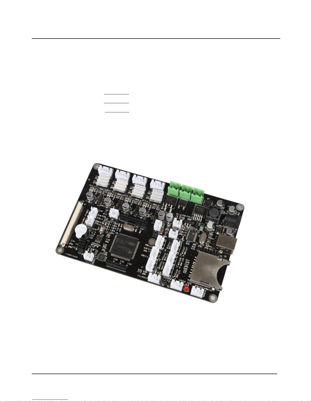
Chitu V3.6 User Manual
Compiler:Pitt Xie Date: 01/11/2015
Reviewer:David Yi Date: 01/11/2015
Approver:Sam Lin Date: 01/11/2015
Page 2

Copyright Declaration
The manual is only used for the purchaser. Any part of this manual
shall not be reproduced or disseminated for any purpose or in any way such
as electronic format and mechanical means or other methods, including
photocopy and record without written authorization of CBD-Tech.
Technical Supports
Please contact us if you have any interest in finished product of 3D
printed pieces, development board and related modules or is you desire for
more technical information as well as supports:
TEL: +860755-23103569
Official website : www.cbd-3d.com
EMAIL: [email protected]
QQ: 2056288869
If you have any technical problems, please visit CBD-Tech technical
forum(http://www.cbd-3d.com/forum/ ) and download the information
you need.
Page 3

1.Introduction
The main board of “Chitu” carries high speed microchip with 32 bit,
adopting self-developed firmware that enjoys the advantages of open source
firmware. Besides, it also carries out repeated optimization, employing SD
file configuration mode which will bring about convenient and quick
renewal.
“Chitu” mainboard matches color touch screen, enjoying simple interface
and high sensitivity. The firmware has experienced arc optimization, PID
temperature stability optimization, which is in favor of breakpoint saving
and shutdown automatically after printing. Currently, we can provide the
services of customized operation interface of the screen, customized APP on
the mobile phone, and customized software on PC, offering you a platform
to show your company. This system is bilingual and can be switched
between Chinese and English by one button. CBD-Tech can provide the
services for different languages.
1.1 Parameters of Mainboard
External Dimension:150*100mm
Microprocessor : STM32
Input Voltage : 12V~24V 10~15A
Power Interface: Switching power supply or adapter
Motor Driver: Allegro A4988 (1/16 microstepping)
ChiTu V3.6 can be externally connected motor drive
Motor Driven Interface: Single head motherboard has four motor interface
Double head motherboard has five motor interface
Temperature Sensor Interface: 3 paths of 100K NTC (thermistor)
2 paths of MAX6675(thermocouple)
Color Touch Screen: 2.8 or 3.5 inches of TFT
Upgraded Firmware supporting SD card (supports 8G<= FAT 16 and FAT32)
Square USB that is convenient in pull and plug,Communication Baud Rate is 115200
File Format Supported: G-code
Machine Structure Supported: XYZ type, Ultimaker type, Hbot type, Delta,Kossel type.
Recommendation of Software: Cura/Repetier-host/Makerware/Simplify3d
Expandable modules: WIFI module, power module( continue to print after power off), large
motor drive, SD card module, USB drive module
Page 4
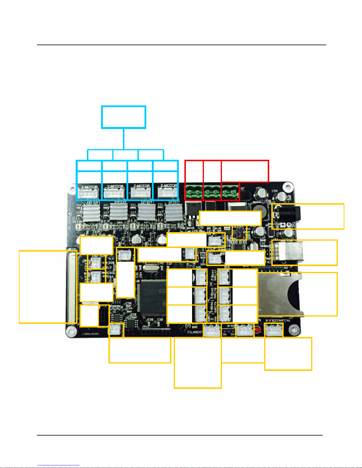
1.2 Interface Layout
Single-head Mainboard
X-min
Y-min
Z-min
Y-max
Z-max
X-max
E-Temp
expansion
interface
B-Temp
WIFI
USB
Power off
module
interface
Stepping Motor
E1 Axis Z Axis X Axis Y Axis
12-24V
supply
Hot
Bed
Hot
End
5V/12-24V Jumper
End fan
Board fan
5V
Light
bar
2.8 inch or
3.5 inch
Interface of
color touch
screen
Hot-End
Thermocouple
(optional)
Switch of
Automatic
leveling and
broken wires
test etc.
24V Light bar
Power adapter
SD Slot
USB
Power adapter
SD Slot
USB
Power adapter
Page 5
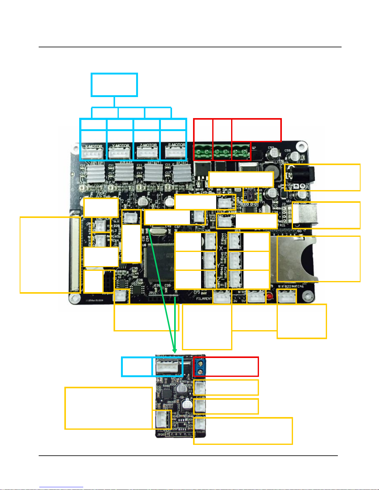
Double-head Mainboard
E2 Axis
Thermistor E 2
Hot-End Thermocouple 2
(optional)
Hot End 2
End fan 2
Switch of Automatic
leveling and broken
wires test etc.
X-min
Y-min
Z-min
Y-max
Z-max
X-max
E-Temp
expansion
interface
B-Temp
WIFI
E1 Axis Z Axis X Axis Y Axis
12-24V
supply
Hot
Bed
Hot
End
5V/12-24V Jumper
End fan
Board fan
5V
Light
bar
Hot-End
Thermocouple
(optional)
24V Light bar
Switch of
Automatic
leveling and
broken wires
test etc.
Power off
module
interface
2.8 inch or
3.5 inch
Interface of
color touch
screen
SD Slot
USB
Power adapter
Stepping Motor
Page 6
2.How to Use
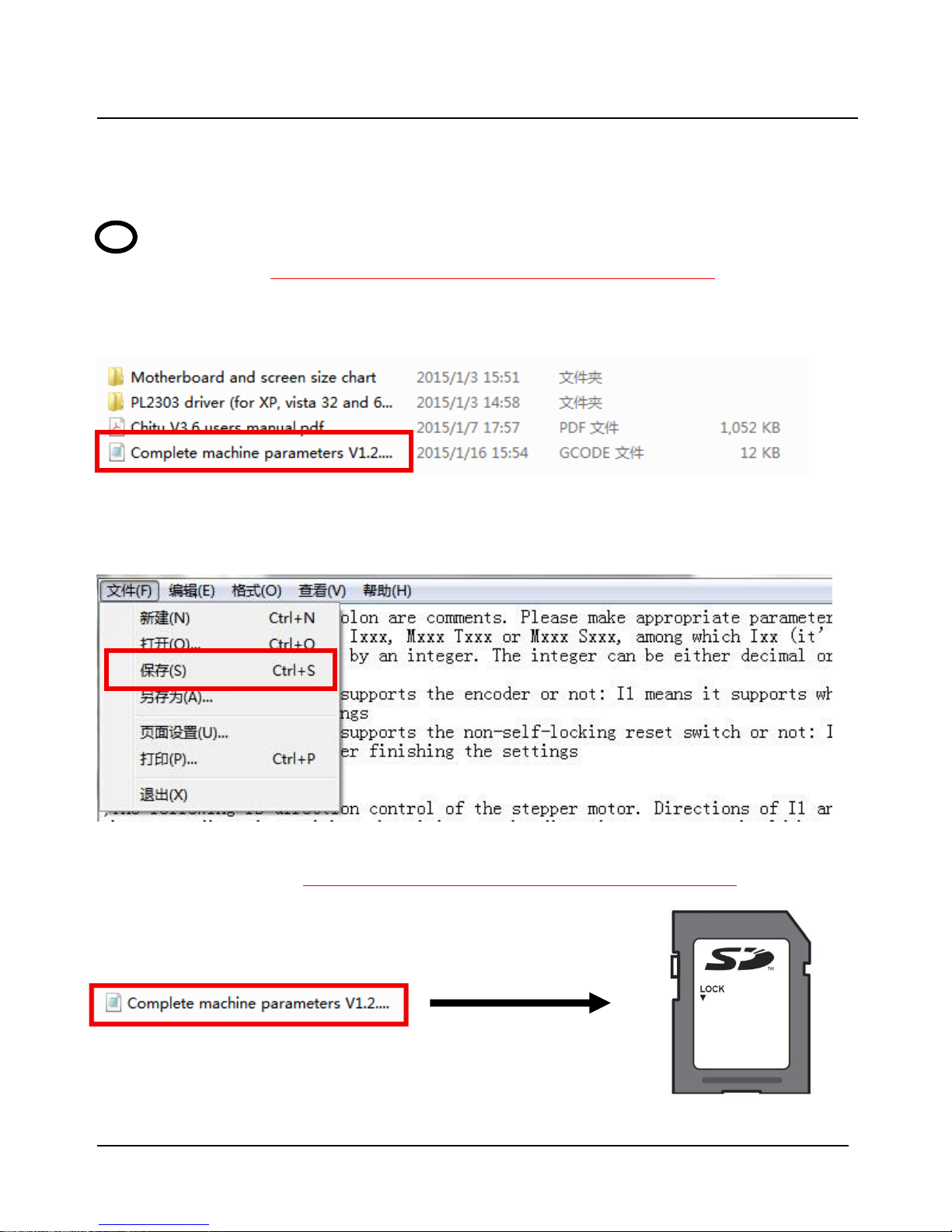
1 Firmware Parameters Setting
Open the file of Complete machine parameters V1.2.30.gcode ( the one
with the notepad icon with file ending .gcode)with notepad. Set the related
parameter in line with machine parameters, which is shown as follows.
Click to “save” after allocation, which is shown as follows.
Take the allocation of Complete machine parameters V1.2.30.gcode into SD
card.
SD Card
Page 7
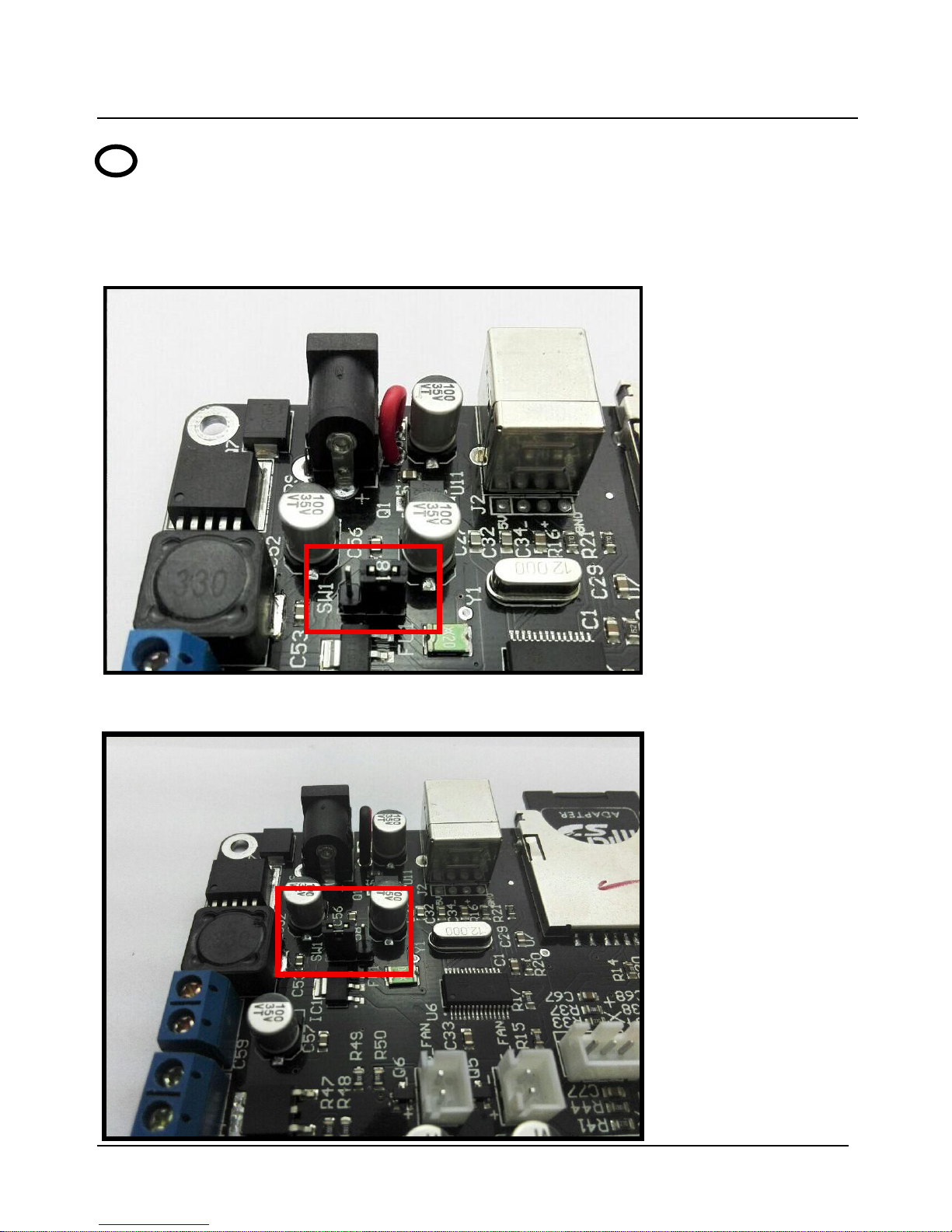
2 Update Firmware in SD Card
Plug the jumper cap of 5V/12-24V, supplying for USB. There are two kinds
of power supply.
USB(5V) Power Supply
Power Supply(12-24V)
Page 8
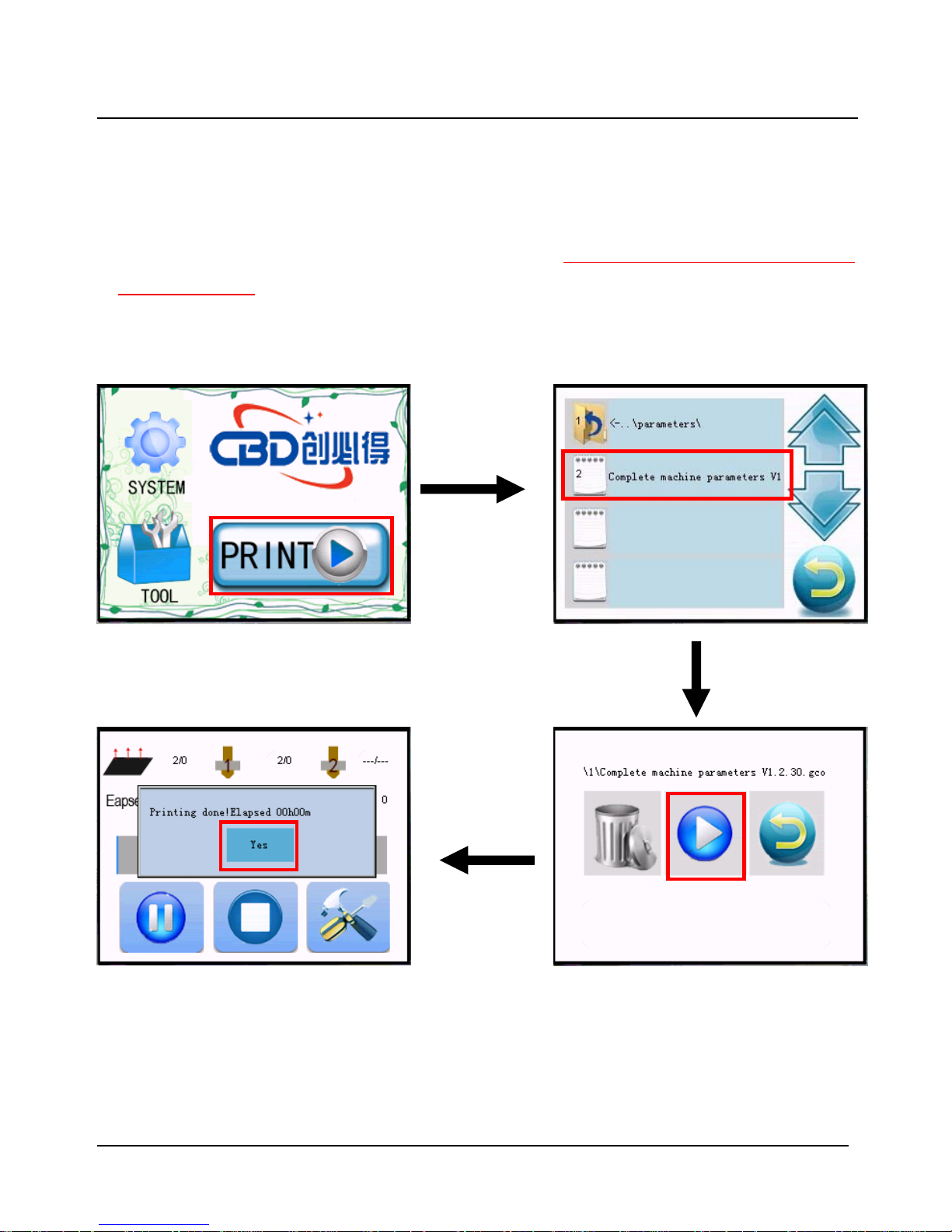
Choose one of the above methods. Take USB supply as example, plug the
jumper cap and connect screen flat cable. The screen will light up.
After the SD card is plugged, choose the file of Complete machine parameters
V1.2.30.gcode and print. When printing is finished(about 2s-3s), the firmware
parameter is updated, shown as following figure.
Page 9
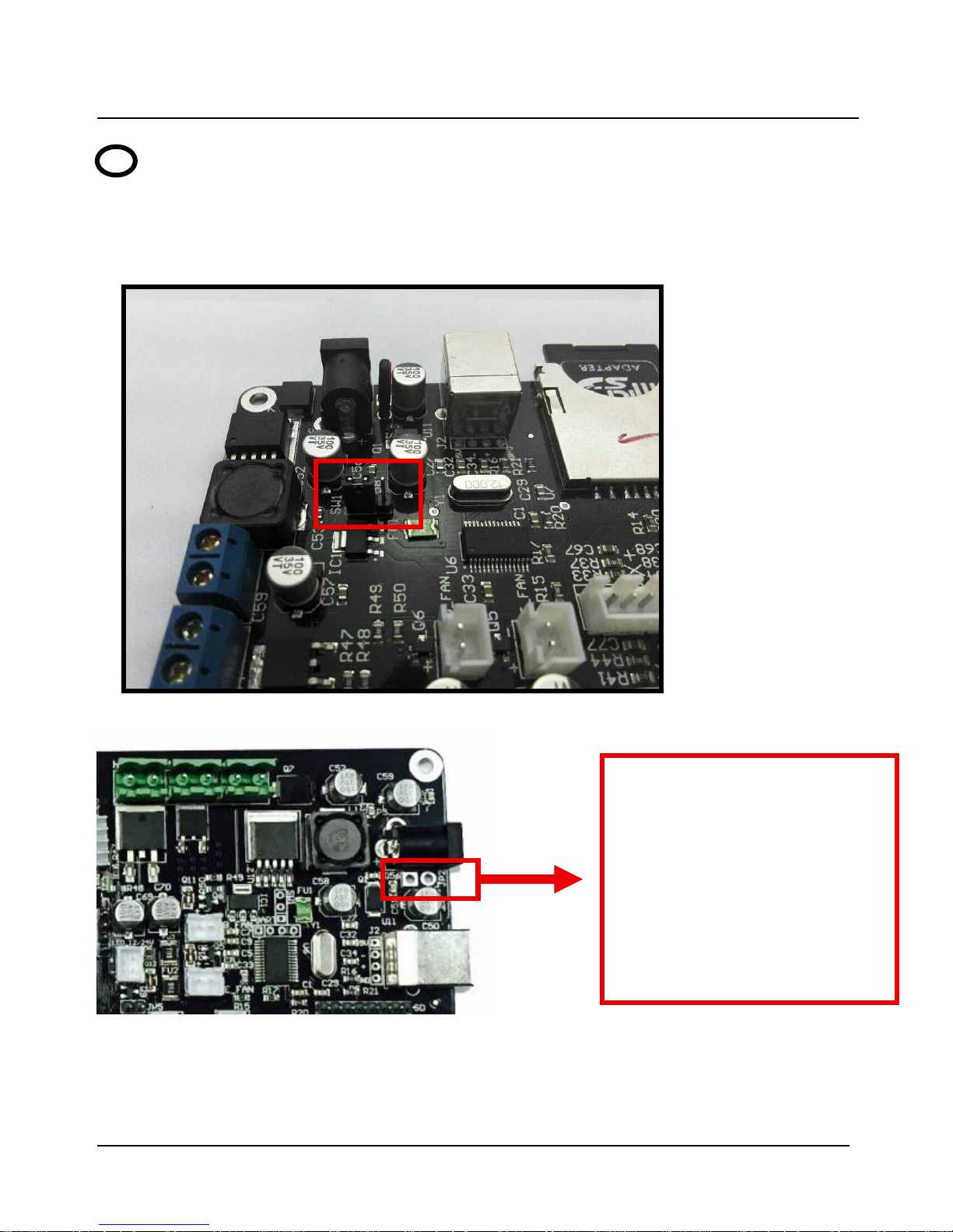
After the connection of all the external devices, plug the jumper cap of 12-24V,
which is shown as follows.
If you use a power adapter, the interface switch needs to be configured, as seen below.
When the machine is initiated, it is recommended to print some small models so as to
test the validity and accuracy of parameters. Make adjustment to parameter according to
print effect until the printing is in good condition.
3 Computer Test Printing
If you use the power adapter,
the switch can be connected
in both holes. If the switch is
not used then use the available
short connection else, the board
will not get energized and will
not work.
Page 10

3.FAQ
1.Why does not the screen light up after the connection and plugging of USB or
power supply?
Answer:
⑴ Wrong connection of power supply jumper cap.
⑵ Poor contact of flat cable on both sides of screen. It is recommended
to pull out and plug again.
(3) If you use a power adapter, you can check whether the switch
interfaces is shorting or not.
2. Why does not the limit switch stop after trigger?
Answer:
⑴ Wrong setting of direction of electrical machine.
⑵ Wrong setting of structure type of limit switch in terms of machine
parameters.
3. The electrical motor does not rotate?
Answer:Wrong connection of electrical motor and false identification
between inverting and non-inverting.
4. Failure in installation of drive? (ChuTu V 3.6 support WIN 8.1 /7/XP)
Answer:At first, you can install the drive(PL2303TA) file in the folder. If
failed, you can download from official website of PL2303TA drive, or
you can one-click install by using the Driver Genius and other driver
installation software
Driver Genius download:
http://www.driver-soft.com/download.html
Page 11
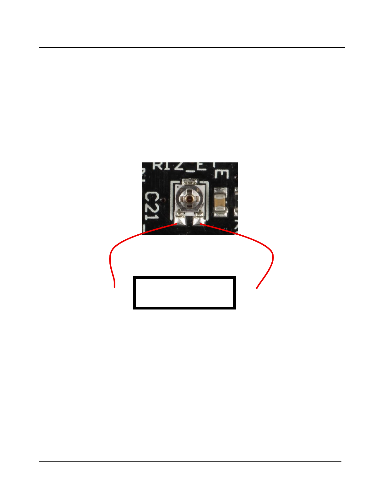
5.How to adjust the drive current of the drive chip?
Answer:
At present, the driving chip current is calculated by I=U/0.8 (driving voltage
divided by 0.8), the factory default is 0.85V, the driving (rotary
potentiometer) voltage is the highest recommendation does not exceed 1.1V
(driving chip current is too high to force the cooling), the following
describes how to measure the driving voltage, as shown below.
+ —
Use a multimeter to
measure voltage
 Loading...