

Page 1

ETHERNET CAMERA, MPEG-4
ZN-L8000
INSTRUCTION MANUAL
ZN-L8210PHA
ZN-L8210NHA
ZN-LN8048PHA
ZN-LN8048NHA
Color or Day/Night High Resolution Camera with Integrated
Computar Auto-Iris Varifocal Lens & MPEG-4 Streaming Video
1
Page 2

Copyright This manual is the intellectual property of CBC (America) Corp. All
rights reserved. No part of this document may be reproduced or
transmitted for any purpose, by any means, electronic or mechanical,
without the express written permission of CBC (America) Corp.
Edition: v2.0 - English
April 2004 (based on CBC (Europe) Ltd. version 2.00)
Note This manual was compiled with the greatest of care and all
information has been double-checked for accuracy. At the time of
printing, all descriptions were complete and correct. Because of the
further development of the products, the content of the manual may
change without prior notice. CBC (America) Corp. will not be liable for
damage which is directly due to errors, incompleteness or any
discrepancies between the manual and the product described.
Trade Marks All names used in this manual regarding hardware and software are
registered trade marks and must be treated as such.
This is a FCC Class A product. In a domestic environment, this
product may cause radio interference, in which case the user
may be required to take adequate measures to prevent such
interference from adversely affecting the performance of other
devices in the area.
2
v2.0 - English
Page 3

INDEX
INDEX 3
INTRODUCTION 4
SAFETY INFORMATION 5
PRODUCT DESCRIPTION 6
INSTALLATION 8
CONFIGURATION WITH WEB BROWSER 11
OPERATION WITH INTERNET EXPLORER 26
SERVICE 27
TECHNICAL SPECIFICATIONS 28
3
v2.0 - English
Page 4

INTRODUCTION
This manual is intended for persons authorized to install and operate this camera and
other VCS products. International, national and any relevant regional regulations relating
to electronics must be observed at all times.
Conventions
In this manual, the following symbols and notations are used to draw attention to special
situations:
Attention! This symbol indicates tips and notes that make using the device
easier and more convenient.
Hazard! This symbol indicates that failure to follow the safety instructions
given may directly endanger people, cause damage to the system or to other
equipment. This symbol represents a direct threat of danger.
The following typographic conventions are used in this manual:
Configuration menu names and window and key names and parameters
[Enter], [C] separate key names
[Ctrl] + [C] two or more keys pressed simultaneously
ping command line input and output
-
Intended Use
This camera is intended to transmit video and control signals via Ethernet data networks.
This camera is designed for use in CCTV systems.
The connection of an external alarm sensor allows functions to be triggered automatically.
Other unauthorized applications are not permitted.
If you have any additional questions concerning the use of these devices which are NOT
answered in this manual, please contact your dealer.
This camera is compatible with following VCS products: VideoJet10e and VIDOS software.
4
v2.0 - English
Page 5

SAFETY INFORMATION
Electrical Shock Hazard
Ø Never attempt to connect the unit or the power supply to any power source other
than the one for which it was provided for.
Ø Use only appropriate and approved power supply units with this device (see
technical specifications).
Ø Do not open the housing of the power supply unit.
Ø Disconnect the power supply unit from the outlet and from all other devices if a fault
occurs.
Ø Install the power supply unit and the device in a dry place, which is protected from
the elements.
Ø If you are uncertain about the safe operation of the unit, shut it down immediately
and secure it to prevent any unauthorized start-up. Safe operation of this unit is no
longer possible under the following conditions:
§ If damage is visible to the unit or the cables
§ If the unit no longer operates correctly
§ If the unit has been exposed to rain or moisture
§ If objects have penetrated inside the unit
§ After long storage under improper conditions or
§ After heavy demands during transport
Installation and Operation
Ø All applicable electrical codes and regulations must be observed and followed at all
times during the installation of this device.
Ø Before installing or operating the system, ensure that you have read and
understand the documentation for all other equipment that will be connected to the
unit, such as monitors or pan-tilt (PTZ) heads. These documents may contain
important safety notices and information concerning permissible applications.
Ø Please only install and operate this device as described in this manual. All other
work beyond this may lead to injuries to persons and damage to the system or
other equipment.
Ø Ensure a secure footing whenever working in elevated positions. Use only
approved safety ladders. If necessary, use a safety harness or railings.
Ø Use this camera with original Ganz tools.
Repairs and Maintenance
Ø Never open the housing of the unit.
Ø Never open the housing of the power supply unit.
Ø Only allow a qualified technician to perform maintenance or repair work.
Ø Contact your dealer for authorized service or repair.
5
v2.0 - English
Page 6

PRODUCT DESCRIPTION
System Requirements
Ø PC with Windows 98/2000/XP operating system and network connection
Ø Microsoft Internet Explorer web browser (version 5 and up) or serial interface and
terminal program, e.g. Windows Hyperterminal
Configuration Requirements
Ø Computer with Windows 98/2000/XP operating system and network connection
Ø Microsoft Internet Explorer (version 5 and up) and MPEG-ActiveX plugin
Operating Requirements
Ø Computer with Windows 98/2000/XP operating system and network connection
Ø Microsoft Internet Explorer (version 5 and up) and MPEG-ActiveX plugin
Ø VideoJet10e with NTSC / PAL monitor or VIDOS software
Functions
This device is a high-resolution color or Day/Night camera for professional use in CCTV
systems. It has an integrated video server for encoding the video and audio signals for
transfer via an Ethernet LAN.
The camera’s ¼” CCD offers a horizontal resolution of 480TVL(PAL) / 470TVL(NTSC).
The camera is characterized by a 2.8-10mm (color) or 4-7.5mm (Day/Night) Computar
varifocal lens, with DC auto-iris.
All of the camera settings are accessed via HTML pages using an Internet Web Browser,
except the anti-flicker function, backlight compensation (BLC) and iris setup.
Main functions are:
Ø Automatic DC iris and varifocal lens
Ø BLC and anti-flicker
Ø AGC ON/OFF
Ø Analog video output PAL/NTSC (BNC) for focus and iris setup
6
v2.0 - English
Page 7

Multicast functions
This camera utilizes MPEG-4 compression technology. Thanks to efficient encoding, the
data transmission rate remains low, even with maximum image quality at 25 images per
second; furthermore, it can be adapted to meet the bandwidth requirements of various
network infrastructures.
In appropriately configured networks, the multicast function permits the simultaneous video
transmission in real time to several receivers. A requirement for this to function properly is
the implementation of the UDP and IGMP protocols on the network.
Configuration
This camera can be configured with a browser via the local area network or
through the Internet. Firmware updates and the quick uploading of device
configurations are handled in the same way. Please note that disconnecting
the camera or power supply while the firmware update is still in progress can
cause serious damage to the camera.
Summary
Ø Video and Data Transmission over LAN / WAN networks
Ø Digitally optimized video data
Ø Automatic Iris Control
Ø Integrated Computar Varifocal lens
Ø Multicast or video streaming multicast connection
Ø Local analog (NTSC / PAL) video output
Ø 25 FPS (at high resolution)
Ø MPEG-4 or M-JPEG
Ø Integral Ethernet interface 10/100 Base-T RJ-45
Ø Remote control of internal functions via TCP and UDP
Ø 3-step Password Protection
Ø 2 Alarm Inputs (NO or NC)
Ø 1 Relay (NO or NC)
Ø Automatic connection on alarm
Ø Integrated motion detector
Ø Firmware upgrade by flash memory
Ø Bi-directional audio transmission
7
v2.0 - English
Page 8
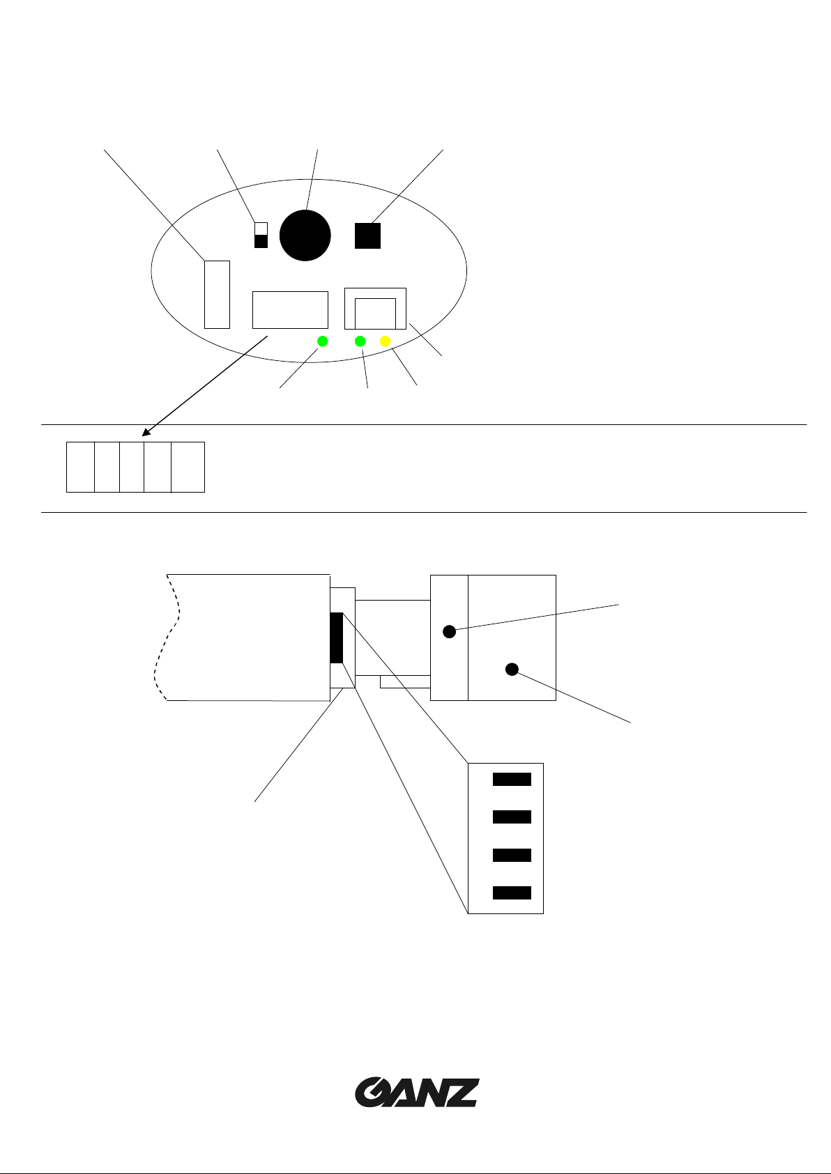
Connectors and Controls
1 8 3 4
1 USB Port
2 Power Supply LED
3 Analog Video Output (BNC)
4 Day/Night Control Terminal (NO)
(Only on Day/Night models)
5 10/100 Base-T LAN (RJ-45) connector
6 Link LED
7 Transmission LED
8 Video termination switch (75 Ohm/High)
1 3 5 7 9
2 4 6 8 10
5 / 8
1 Line Audio In
2 GND
3 Line Audio Out
4 GND
5 ALARM IN 1
6 ALARM IN 2
7 Relay
8 Relay
9 12 V DC
10 GND
6
7
1
2
1 DC iris: ON
2 Anti-Flicker: ON/OFF
3 BLC: ON/OFF
4 Always ON
3
4
5 VR for iris adjustment
6 Zoom adjustment
7 Focus adjustment
8 DC iris connector
8
v2.0 - English
Page 9

INSTALLATION
This camera is designed for indoor operations. Choose a site for installation
which ensures that the camera is NOT exposed to extreme temperatures or
extreme moisture or humidity. The ambient temperature must be between
+40°F and 115°F (+5°C ~ 40°C) and the relative humidity cannot exceed 80%.
During operation, the unit generates a good amount of heat. Please ensure
sufficient ventilation and install this device away from heat-sensitive equipment
or objects.
Please observe the following installation conditions:
Ø Do not install the camera in the immediate vicinity of radiators or other sources of
heat. Avoid installing the camera where it is exposed to direct sunlight.
Ø Ensure sufficient space for laying the cables.
Ø Ensure adequate ventilation of the camera.
Ø For all cable connections, use cables which prevent electrical interference, where
necessary.
Ø Ensure that the camera is not exposed to water at the installation site. If necessary,
use fresh desiccant in waterproof housing to avoid moisture due to condensation.
Ø Lay and install all cables in such a way that they cannot be damaged and ensure
sufficient strain relief.
Ø The camera mounting position always depends on the actual situation. No concrete
instructions can be given here. The camera has a standard ¼”thread which can be
installed on both the top and bottom of the housing.
Ø Lay all cables up to the installation position.
Ø If necessary, connect a monitor with a coax cable to the BNC jack in order to be
able to check the video image on the spot (line impedance must be set by the switch
#8 to HIGH).
Ø Connect the leads of the power supply unit to terminals + and – of the DC 12V
CONNECTOR. Pay attention to the correct connection of the leads.
Network Connection
You can connect the camera via hub, switch or router to a 10/100 Base-T network. Use a
standard UTP Category 5 cable with RJ-45 connectors.
Alarm Inputs, Relay Output
The alarm inputs of the camera will allow you to connect to an external alarm trigger. If
configured accordingly, an alarm trigger can, for example, set up an automatic connection
between the camera and a remote station.
9
v2.0 - English
Page 10

The relay output allows for switching external devices. This control output can be used
interactively during an active connection with the camera. The contact can be programmed
as normally open (NO) or normally closed (NC) and it is possible to invert the mechanical
function by software setup.
The relay contact must not be subjected to a load of more than 40V and 0.8A.
Power Supply
This camera has no master power switch. When you have connected the power supply
unit to the device and insert the power plug into a socket, the device is powered on and
ready for operation.
Assigning the IP Address
Ø Start the ‘Jet Manager’program.
Ø Click on ‘scan’ icon.
Ø Select the desired ‘ZN-L8000’ and right-click to bring up the context menu.
Ø Click on “Change IP Address”.
Ø Click on “IP Pool”if you have not yet specified a valid IP address range and set it.
Ø Select “Set manually”and choose a valid IP address.
Ø Click on “OK”
Ø Wait few seconds and click again on ‘scan’ icon to view new IP address in the list.
Ø Select again the ‘ZN-L8000’ and right-click, selecting “View in Browser”to view the
camera in Microsoft Internet Explorer.
Day / Night Manual Control Function
Only the ZN-LN8048PHA and ZN-LN8048NHA Day / Night Models feature the N.O. input
terminal (#4). This terminal will manually switch the camera from color (open contact) to
B&W (closed contact). When this terminal is closed, the camera switches into Night Mode
and adjusts the DC iris by fixing the AES speed.
When the camera switches to Night Mode automatically, the DC iris is completely opened
and the AES speed is adjusted by the camera.
10
v2.0 - English
Page 11

CONFIGURATION WITH WEB BROWSER
Making the Connection
The integrated HTTP server offers you the possibility of configuring the camera over the
network with a web browser. This possibility is far more convenient than the configuration
via the terminal program and also allows you to view live video images.
In order for live video images to be decoded, the special MPEG ActiveX control
required must be installed on the computer. The latest version of the MPEG
ActiveX control may be installed from the supplied CD, or downloaded from our
website. Notes on operation of the web browser can be found in the online
help file.
System Requirements
Ø Microsoft Internet Explorer (version 5 and up)
Ø Microsoft Java Virtual Machine (in case of Windows Pro XP, your dealer can provide
you this software)
Ø Network connection
Establishing the Connection
To use the camera on the network, it must be provided with an IP address.
The following address has been preset at the factory:
IP Address 192.168.0.1
Subnet Mask 255.255.255.0
Gateway 0.0.0.0
Type the camera’s IP address into the web browser’s address bar. If the address is not
compatible with your network, you can easily change it using the JetManager software that
you can download from our website.
Configuration
Once the Livepage has loaded, click on Settings to view the configuration pages.
11
v2.0 - English
Page 12

Click on the items in the left gray bar to navigate the configuration pages. The pages are
divided into categories; click on each category and then on the desired subject.
To save your changes, it is necessary to click the Set button on each screen
before moving on to another category of settings.
Unit Identification ó General Settings
Unit name:
Enter a name for the camera to aid in identification in multiple camera systems.
Unit ID:
Each device can be assigned a unique identifier which can be used to identify it.
12
v2.0 - English
Page 13

Unit Identification ó Password Settings
Password level:
Access to the camera is generally protected with a password in order to prevent
unauthorized use of the device. The transmitters operate with three authorization
levels: Live, User and Service.
Service - for configuration, services control and live picture.
User - for services control and live picture.
Live - for live picture only.
Password:
You can define and change passwords for access to the device when you are
working with the authorization level ‘Service’ or if the device is not protected with a
password. Please enter the password.
Password Confirm:
Type the new password again and click Set.
Unit Identification ó Language Settings
Website language: select the desired language of the HTML pages.
Unit Identification ó Time Settings
If a number of cameras are combined in a system, it is important that the internal clocks of
the separate units are all synchronized.
Date Format: select here the desired date format, based on your country.
Europe: DD.MM.YYYY USA: MM.DD.YYYY Japan: YYYY.MM.DD
Unit Date/Time: manually enter the date and time or click on Synchr. PC to update the
date and time, in synchronization with the PC’s current date and time.
13
v2.0 - English
Page 14

Unit Identification ó Time Server Settings
The camera can receive a time signal from an NTP server and use it to set the internal
clock. The device calls up the time signal automatically every two hours.
Time zone: select the current time zone.
Time server IP address: enter the IP address of the NTP server.
Display Settings ó Camera name
Camera 1:
Enter here the camera name, click Set.
Display Settings ó Display stamping
You can configure the device so that the camera name, time and alarm source are
displayed on the video image. Select Top if the names are to be displayed at the top of the
image, or Bottom if the names are to be displayed at the bottom of the image. If you do not
wish the names to be displayed, select Off.
Camera name stamping:
Camera name is shown in the LH corner of the video image.
Time stamping:
Date and time are shown in the RH corner of the video image.
Alarm mode stamping:
Select On to display the alarm source (e.g. motion alarm) in the video image.
Select Off to not display the alarm source.
Displayed alarm message:
The text that should be displayed during an alarm event.
14
v2.0 - English
Page 15

Video/Audio Settings ó MPEG-4 Encoder
The data transmission parameters can be configured to suit the local operating
environment (e.g. network architecture, bandwidth, data structures).
The ZN-L8000 camera can provide you the power of 2 independent MPEG-4 Encoders that
you can use at different transmission bandwidths, resolutions, etc. for remote transmission,
local transmission or recording, in order to optimize your system and network usage.
Name of first/second encoder:
Enter a name for the selected encoder
Parameter preset:
Input a name for the selected setup to recall it later.
Datarate:
Select the desired data rate (max 5000 Kbits per second, about 5 Mbps.)
Video quality settings:
Here you can select if the camera can automatically optimize the video quality or set
this value manually. In Manual mode, move the bar close to “High”if you prefer
picture quality over video refresh or otherwise (“Low”) you prefer good refresh rate
over picture quality.
Intra frame distance:
The number of frames to be sent between two Intra-frames.
Frame skip ratio:
With this parameter you define which frames are encoded. If '1' is selected all
images are encoded. When '2' is selected only every other image is encoded, etc. the lower the bandwidth the higher this value should be in order to have highestquality video.
15
v2.0 - English
Page 16

Video resolution:
You can choose between these resolutions:
Low 176 x 144 pixels (QCIF)
Standard 352 x 288 pixels (CIF)
High 704 x 288 pixels (2CIF)
Reset this parameter preset:
When the 'Default' button is pressed, the parameters for the selected profile are
reset to the factory default values.
If the MPEG ActiveX control is not installed on your computer, a corresponding
message will be displayed when you switch to the live image page. The latest
version of the MPEG ActiveX control may be installed from the supplied
software CD, or downloaded free from our website.
Video/Audio Settings ó Video Input Settings
If a local analog video output connector is used, this page will allow you to open the line 75
Ohm termination to use with other devices. Please set to On if external video peripherals
are not being used (this setting must be identical to the position of the external 75
Ohm/High impedance video line termination switch).
Video/Audio Settings óAudio Settings
Activate audio:
Switch this option On if you want to send an audio stream along with the MPEG-4
video. Transmitting audio requires additional bandwidth of approximately 80 Kbps.
When audio is set to On, it is stored together with the video stream when centralized
recording is active; audio can not be recorded on local storage media.
Alarm settings ó Alarm sources
16
v2.0 - English
Page 17

Video loss alarm:
Select the option On if the unit is to activate an alarm when the video signal is
interrupted.
Unified picture detection:
This function constantly checks the contrast of the video image and triggers an
alarm when the video is locked, for example, when the lens is covered.
Motion alarm:
Select On if the unit is to activate an alarm when the motion alarm is triggered.
Alarm input 1/2:
Select the option On in order to activate the alarm by means of an external alarm
sensor. Otherwise select Off. If this setting is turned On, you must also select if the
alarm is activated by an Active high or Active low voltage level. Enter into the text
field a message for the alarm input which will be displayed on screen if an alarm is
activated.
Alarm Settings ó Alarm Connections
Options are provided to specify the behavior of the devices in the event of an alarm.
Connect on alarm:
Select On, to automatically establish a connection to one of the predefined IP
addresses in the event of an alarm. The addresses will be contacted in turn once
until a connection is established.
Select Assign IP to input if you want a predefined allocation of alarm input and
remote IP address. Thereby only one remote IP address will be contacted in case of
an alarm, namely the first IP address with alarm input 1 being triggered, the second
with alarm input 2 and so on.
Choosing the parameter Follow input 1, a connection to the first IP address is
established when alarm input 1 is triggered and holds only until there is a contact at
alarm input 1. For example, the connection is established if a push-button connected
to alarm input 1 is activated and will be disconnected automatically when the button
is turned off.
Number of video receiver address:
The ZN-L8000 can store up to 10 alarm IP addresses. In case of an alarm, the
addresses are contacted one after the other until a connection is established.
17
v2.0 - English
Page 18

Alarm IP address:
You can enter the IP addresses of a possible receiver.
Remote receiver password:
Here you can enter the respective receiver password in case the receiver is
protected by one.
Live video auto-connect:
Select the option On if it is required to re-establish a connection to the previously
specified IP address after each restart, e.g. after a connection breakdown or network
dropout. The addresses will be contacted in turn once until a connection is
established.
Alarm settings ó Motion detector
The camera contains an integrated video sensor, which based on the video processing can
register changes in the video signal. These changes are primarily initiated by movement in
the field of view of the camera. The sensitivity of the video sensor can be adjusted, so that
an alarm is generated only if a given threshold is exceeded.
In order for the alarm to operate, the following conditions must be fulfilled:
Ø motion detection must be activated.
Ø at least one cell must be activated.
Ø parameters must be matched to environmental conditions and to required responses.
Ø the sensitivity must be set to a value greater than 0.
Light reflections, switching on or off of floodlights or light level changes caused
by cloud movement in bright daylight can cause undesirable responses from
the video sensor and thereby generate false alarms. Test for different day and
night time conditions in order to ensure correct operation of the video sensor.
For surveillance of indoor areas, ensure a constant lighting of the areas during
the day and at night. Uniform surfaces without contrast can trigger false alarms
even with uniform lighting.
18
v2.0 - English
Page 19

Motion detector:
Select the option On to activate the video sensor.
Select sensor field:
The areas of the image to be monitored by the video sensor are selected here. The
video frame is subdivided into 396 square cells. Each of these cells can be
activated or deactivated. If it is necessary to exclude particular regions of the
camera field of view from the monitoring process because of, say, continuous
movement (e.g. due tree movement in a wind), the relevant cells can be deactivated
(use mouse click for this operation)
Local sensitivity:
The basic sensitivity of the video sensor can be adapted for the ambient camera
conditions. The sensor reacts to brightness variations in the video image. The
darker the observation range, the greater the value that must be selected here.
Adjust the sensitivity by moving the slider to the desired setting with the mouse key
held down.
Average n [frames]:
It is possible to define the number of frames during which a movement is monitored
in order to generate an alarm. In this way, it is possible to prevent generating a false
alarm, e.g. by a bird flying across the surveillance area. Select the desired value by
moving the slider to the desired position with the mouse key held down.
Object min size [n*] blocks:
The number of sensor cells, which a moving object must cover in order to generate
an alarm, can be specified. In this way it is possible to prevent too small objects from
producing an alarm. For this, the minimum recommended value is 2 (2 × 2 sensor
fields). Select the desired value by moving the slider to the desired position with the
mouse key held down.
Alarm indicator:
To prevent false alarms, a motion signal can be matched to a given alarm threshold.
In this way, for example, it is possible to filter out effects caused by the background
noise generated in the camera itself. The blue line indicates the alarm threshold.
Any value greater than this will produce an alarm signal. The components of the
motion signal generating the alarm are indicated in red. The alarm threshold can be
varied to suit individual requirements.
Take note of the amplitude of the movement signal displayed in the window over a
long period and at all light levels likely to be encountered in practice. Move the
mouse pointer onto the blue line. Holding the left mouse button pressed, move the
blue line to the required position.
Motion tracking:
For certain applications, it can make sense to generate an alarm only if movement
takes place in a particular direction. You can activate the motion detection and
select the direction of movement required to generate an alarm. Select the option
On, in order to activate the motion tracking feature of the video sensor.
19
v2.0 - English
Page 20

Tracker:
In the Tracker field you see an arrow, which indicates the current motion in the
video image. By means of check boxes in the four corners, the desired direction can
be activated. If, for example, all movements to the “left”and “upwards”are to
activate an alarm, then mark the top left corner. If all movement to the “left”is to
activate the alarm, then check the left upper and the lower left corners. Note the
movements indicated by the arrow in the video image over a long period and at all
light levels likely to be encountered in practice. Click the check box in order to
activate the corresponding directional component.
Relay Setting ó Relay Configuration
The switching conditions for the relay output can be configured. The function of an open
switching relay (normally closed contact) or a closed switching relay (normally open
contact) can be specified. It is also possible to specify whether the output should operate
as a bistable or as a monostable. In bistable operation, the activated state of the relay
remains as switched. In monostable operation, the time can be selected after which the
relay is to revert to its steady state. Various events can be selected to automatically
activate the output. In this way, for example, it is possible to switch on a floodlight when a
motion alarm has been detected and to switch the light off again at the end of the alarm.
Please note that changing the default configuration the relay will work as set when the
camera is powered on but as indicated in the previous session when powered off.
Idle state:
Select Open if the relay is to operate as a normally open contact or Closed if it is to
operate as a normally closed contact.
Operating mode:
Select the operating mode for the relay. If, for example, a lamp is switched on by an
alarm and is to remain on when the alarm has ended, select Bistable. If an acoustic
signal activated by an alarm is to remain on for a period of, for example, 10 seconds,
select 10 s.
Relay follows:
Select a particular event by which the relay is to be activated as required.
20
v2.0 - English
Page 21

The following events can activate the relay:
Ø Off: No relay triggering by events
Ø Connection: Triggering if any connection is established
Ø Video alarm: Triggering caused by loss of the video signal
Ø Motion alarm: Triggering by the motion alarm
Ø Local input: Triggering caused by an external alarm sensor
Ø Remote input: Triggering by a switching contact from a remote location.
Relay name:
The relay can be assigned a name here. The name will be shown on the live page,
depending upon the configuration.
Trigger relay:
Click on the button Relay to manually switch the relay (e.g. for test purposes or to
operate a door opener).
Service Settings ó Network Settings
Unit IP address: the unit’s IP address.
Subnet mask: the unit’s Subnet mask.
Gateway IP address: the gateway IP address (usually the router or firewall)
Video/Audio transmission:
If the device is used in front of a firewall, transmission over TCP (Port 80) should be
selected. If used in a local network select UDP.
Ethernet link type:
Adjust the type of Ethernet link to the network. In most applications, 'Auto' is the
correct choice. For some routers and switches it may be necessary to set the
Ethernet link type to a fixed value.
Select the appropriate value:
10 MBit/s HD = 10 Mbps half-duplex
10 MBit/s FD = 10 Mbps full-duplex
100 MBit/s HD = 100 Mbps half-duplex
100 MBit/s FD = 100 Mbps full-duplex
21
v2.0 - English
Page 22

DNS Server IP Address:
When working with a device over the Internet, dynamic IP addresses are assigned
for efficient use of the IP address pool, i.e. the device gets a new (changing) IP
address each time a connection is set up. Connecting is easier when the device is
listed on a DNS server. The device logs in regularly, leaving the device name,
device IP address and the current Internet IP address.
To connect to a device over the Internet you just insert the device name together
with the URL of the DNS server, which then returns the valid Internet IP address for
automatic connection set up. The default setting for the DNS server IP address is
the IP address of the VCS DNS server videotec.info. The ZN-L8000 contacts the
server automatically when a refresh time is specified in the next parameter. The IP
address of the VCS DNS server is 195.145.107.78.
DNS refresh time: enter here the time interval for the ZN-L8000 to contact the DNS
server. You can enter a value from 30 to 86400 sec (24 h). Leave
this field empty if you don't want to use the DNS function.
Multicast operation is only possible using the UDP protocol. The TCP
protocol does not support any multicast connection.
Due to settings inside this device, the following ports in your network have to be opened:
TCP (Port 80): port 80
UDP (without Multicast): all UDP ports starting with port 1024 and TCP port 1756.
UDP (with Multicast): the defined Multicast video port and the consecutive 7 ports.
Service Settings ó Multilink – Multicast
Along with a 1:1 connection between a transmitter and a receiver (unicast), the units
provide the option of connecting a number of receivers to simultaneously receive the video
signal. This is achieved either by a duplication of the data stream in the unit with
subsequent distribution to a number of receivers (multi-unicast) or by distribution of a single
data stream on the network itself to a number of receivers in a defined group (multicast).
Requirement for multicast operation is a multicast compliant network with
implementation of the UDP protocol and the IGMP protocol. Other group
management protocols are not supported. The TCP protocol does not support any
multicast connection.
22
v2.0 - English
Page 23

The devices support the multi-unicast operation up to a maximum of 5 simultaneously
connected receivers for MPEG-4. The transparent data connection is maintained from the
first unit. However, after 15 seconds of inactivity the data connection is automatically
suspended and another unit can exchange transparent data with the transmitter.
For multilink operation, the network is not required to be multicast compatible as the
devices are also multi-unicast compatible. Duplication of the data in the unit requires
considerable processor power and, under certain circumstances, leads to limitations in the
picture quality.
Multicast streaming:
Select the option On in order to activate the multicast function. For that purpose a
valid Multicast group IP address has to be entered.
Multicast group IP address:
Before you and use the multicast and the streaming mode in a multicast-compatible
network, you must establish a special IP address (class D address). The network
must support the establishment of a group IP address and the Internet Group
Management Protocol (IGMP). The address range is from 224.0.1.0 to
238.255.255.255. With this field left empty (0.0.0.0) the device is sending in multiunicast mode and streaming is not possible.
Multicast port MPEG-4:
This field is read-only and informs about the selected video port. Assignment of port
numbers is done automatically by the software.
Multicast racket TTL:
Here the number of junctions can be entered a data packet can pass within the
network. By setting the parameter you determine the life span of the data packets,
e.g. if multicast is operated over a router the value must be greater than 1 to
guarantee transmission of the packets.
Service Settings ó Version Information
Hardware and software version numbers are only required for information and can not be
altered. Keep a record of these numbers in case technical assistance is required.
23
v2.0 - English
Page 24

Service Settings ó Livepage Settings
The live page can be set up to suit individual requirements. Options are provided here to
display different information and operating elements along with the video picture. In
addition, individual background images for the main window and for the upper screen area
(banner) can be used.
For the background image you can use the file types GIF and JPEG. The file
paths must correspond to the type of access (for access to a locally stored file,
for example, c:\Images\Logo.gif, for access to an Internet/Intranet file, for
example, http://www.cbcamerica.com/images/logo.gif). Note that with Internet
or Intranet access, the connection must be maintained in order to continually
display the image. The image files are not stored in the device.
Start page background URL:
Enter the file path to a suitable background image. The image can be stored on a
local computer, on a local network or at an Internet address.
Start page logo URL:
Enter the file path to a suitable image for the upper screen area (banner). The image
can be stored on a local computer, on a local network or at an Internet address.
Video from Encoder on live page:
Select the encoder you want to use for viewing in the web browser, on the livepage.
Select all items that you want to view on the Livepage; you have choice of alarm,
relay, show alarm messages and show general messages. (all shown by default)
Save alarm logfile to hard disk:
Select this option to store alarm data in a text file on the local computer.
24
v2.0 - English
Page 25

Save general logfile to hard disk:
Select this option to store the logfile in a text file on the local computer.
File for saving alarm messages:
Enter the path to the location where the log files for the alarm messages are stored.
File for saving general messages:
Enter the path to the location where the log files for the general system messages
are to be stored.
Path for JPEG/MPEG-4 files:
Enter the path to the storage location for the JPEG snapshots and video sequences
which can be stored from the live page or the DRAM-Replay.
Service Settings ó Software Update
Software upload:
The units are designed in such a way that their functions and parameters can be
updated with firmware (device software). In such cases, transmit the updated
firmware package via the selected network to the device. On termination of the
connection, the firmware will be automatically installed. This allows a device to be
remotely serviced and updated without a technician having to modify the device
installation on site.
Before starting the firmware upload, ensure that you have selected the correct
upload file! An upload of other files can result in the device being no longer
addressable and having to be replaced. Please remember that you can damage
a camera interrupting a firmware upload.
Configuration download:
You can store the configuration setting of the device on a PC and upload stored
configuration settings from a PC to the device. (Click on Download)
Configuration upload:
Upload the configuration by selecting a file and clicking Upload.
Reset operation
In order to activate the new configuration the system must be rebooted by
entering the current IP address followed by a reset operation.
(http://192.168.0.1/reset)
25
v2.0 - English
Page 26

OPERATION WITH INTERNET EXPLORER
You must use Microsoft Internet Explorer from version 5, the Microsoft Java
Virtual Machine and please disable the java script debugging.
You need to install the MPEG ActiveX plugin.
Your PC should support a video resolution of 1024 x 768 pixels.
Connection
Once you have configured your device, you may enter the IP address of the camera into
the Internet Explorer address bar. (using 192.168.0.1 or http://192.168.0.1/ is acceptable.)
Alarm Input Status
Picture Dimensions (352 x 288 or 704 x 576 pixels)
Relay
Alarm Messages
JPEG Snapshots
Event Messages
Start or Stop Recording
MPEG-4 Streams
26
v2.0 - English
Page 27

Snapshot
Individual images can be displayed in different resolutions. To select the resolution,
append the corresponding parameter to the command snap.jpg:
Ex: 192.168.0.1/snap.jpg
Ø Snap.jpg?JpegSize=S 176 x 144 pixels
Ø Snap.jpg?JpegSize=M 352 x 288 pixels (default value)
Ø Snap.jpg?JpegSize=XL 704 x 576 pixels
SERVICE
The connection between two IP addresses can be checked using the command ping. You
can thus check whether the device in the network is active.
Ø Open the DOS input window and enter the command ping followed by the IP
address of the device. (Ex: ping 192.168.0.1)
Ø When the device is found, you receive in response: Reply from ..., followed by the
number of bytes transmitted and the transmission time in milliseconds (ms). Other
messages, such as a time out or unreachable, this indicates that the device cannot
be addressed via the network. This can have the following causes:
The device is not physically connected to the network. In this case, check the
connecting leads, and the link lights on all devices. Or, perhaps the device is not
correctly integrated into the network with its settings. Check the IP address, the
subnet mask and the gateway IP.
Reset
In order to activate the new configuration the system must be rebooted by
entering the current IP address followed by a reset operation:
ex. http://192.168.0.1/reset
Updated Firmware Download
You can find updated firmware for ZN-L8000 cameras at the following URL:
http://www.cbc-europe.it/cctv/download
27
v2.0 - English
Page 28

TECHNICAL SPECIFICATIONS
Video
Model ZN-LN8048NHA ZN-LN8048PHA ZN-L8210PHA ZN-L8210NHA
System NTSC/EIA (Day/Night) PAL/ CCIR (Day/Night) PAL NTSC
Sensor 1/4" Interline Transfer CCD
Pixels 768(H) x 492(V) pixels 752(H) x 582(V) pixels 768(H) x 492(V) pixels
Scanning System 2:1 interlaced
Sync. System Internal
Scanning freq.
Res. (H) 470 TVL 480 TVL 470 TVL
S/N ratio >50dB
Sensitivity < 0.09 lux (F1.6) @ 30 IRE (Night Mode) < 1.5 lux (F1.2) @ 50 IRE
Gamma 0.45
Video Output 1.0Vp-p / 75O, BNC
White Balance Auto Tracking
DC iris control
AES
Controls
(H) : 15.734KHz
(V) :59.94Hz
Elect. Shutter 1/60 sec. fixed
(1/100 sec. @ FL mode)
1/60 (1/100 sec. @ FL mode)
1/20,000 sec
Anti-Flicker On/Off, BLC On/Off,
Night-Mode On/Off
1/50 (1/120 sec. @ FL mode) 1/20,000 sec
Power
Voltage 12VDC
Power consumption 600mA max.
Dimensions
Dimensions (L) 180 x (W) 80.5 x (H) 59 mm
Operation Temp. 40° ~ 115°F (5° ~ 45°C)
Weight ~400 g (~0.9 lbs)
Lens
Model ZN-LN8048NHA ZN-LN8048PHA ZN-L8210PHA ZN-L8210NHA
Focal length 4 ~ 7.5 mm 2.8 ~ 10 mm
F-stop F:1.6-360 @ 2.8 mm: 1.2 / @ 10 mm: 2.1
Iris control DC
Network
Standard MPEG-4 (ISO/IEC14496), M-JPEG
Bandwidth adjustable –4 Mbps max (MPEG-4)
Video Encoder 176 x 144 QCIF / 352 x 288 CIF / 704 x 288 2CIF
Audio Datarate: 80 kbps / Standard: G.711; 300 Hz – 3.4 KHz
Audio input 1 x mono, 1Vp-p, 50K Ohm
Audio Output 1 x mono, 1Vp-p, min 8 Ohm
Protocols RTP, RTCP, UDP, TCP, IP, HTTP, IGMP, ICMP, ARP, DHCP, *FTP, *SNMP
Software update Flash ROM, remote site programmable
Configuration using web browser (through built-in web server)
Alarm input 2x, max 24V,max load 10 Ohm
Relay 1x, max 40Vp-p, 0,8A
USB * 1 x memory local storage or Wireless LAN (IEEE 802.11) connection
Ethernet 10/100 Base-T, RJ45
(H) : 15.625KHz
(V) :50.00Hz
Elect. Shutter 1/50 sec. fixed
(1/120 sec. @ FL mode)
(H) : 15.734KHz
(V) :59.94Hz
Elect. Shutter 1/60 sec fixed
(1/100 sec. @ FL mode)
1/60 (1/100 sec. @ FLmode)
1/20,000 sec
Anti-Flicker On/Off, BLC On/Off
* with future firmware update
28
v2.0 - English
Page 29

CBC (America) Corp.
Imaging Technology Division
New York Office
55 Mall Drive
Commack, NY 11725
Tel.: 631 864 9700
Fax: 631 543 5426
cctv@cbcamerica.com
http://www.cbcamerica.com
Los Angeles Office
20521 Earl Street
Torrance, CA 90503
Tel: 310 793 1500
Fax: 310 793 1506
29
v2.0 - English
 Loading...