

Page 1

Operating Instructions
ZC-NAF27
Before installing and using the camera,
please read these instructions throughly
and retain them for later reference.
S
Page 2
2
Warning
This is a class A product. In a domestic environment this product
may cause radio interference in which case the user may be
required to take adequate measures.
This symbol is intended to alert
the user to the presence of
uninsulated “dangerous voltage”
within the product’s enclosure
that may be of sufficient
magnitude to constitute a risk
of electric shock to persons.
This symbol is intended to
alert the user to the presence
of important operating and
maintenance (servicing)
instructions in the literature
accompanying the appliance.
CAUTION TO REDUCE THE RISK OF ELECTRIC SHOCK,
DO NOT REMOVE COVER (OR BACK).
NO USER SERVICEABLE PARTS INSIDE,
REFER SERVICING TO QUALIFIED SERVICE PERSONNEL.
CAUTION
RISK OF ELECTRIC SHOCK
DO NOT OPEN
Warning
Regulatory Notices
For U.S.A
T o prevent fire or shock hazard, do not expose the unit to rain or moisture.
To avoid electrical shock, do not open the cabinet Refer servicing
to qualified personnel only.
This equipment has been tested and found to comply with the limits for a Class A
digital device, pursuant to Part 15 of the FCC Rules.These limits are designed to
provide reasonable protection against harmful interference when the equipment is
opearted in a commercial environment. This equipment generates, uses, and can
radiate radio frequency energy and, if not installed and used in accordance with
the instruction manual, may cause harmful interference to radio communications.
Operation of this equipment in a residential area is likely to cause harmful
interference in which case the user will be required to correct the interference at his
own expense.
• A suitable conduit entries, knock-outs or glands shall be provided in thecable
entries of this product in the end user.
• Caution:Danger of explosion if battery is incorrectly replaced. Replacedonly
with the same or equivalent type recommended by the manufacturer. Dispose of
used batteries according to the manufacturer's instructions.
• Holes in metal, through which insulated wires pass, shall have smoothwell
rounded surfaces or shall be provided with brushings.
Page 3

3
Contents
Features................................................................................................................................................................................ 3
Cautions for Safe Operation .............................................................................................................................................. 4
Operating Controls and Their Functions........................................................................................................................... 5
Connections ........................................................................................................................................................................ 6
Control ................................................................................................................................................................................. 7
MENU DESCRIPTIONS ....................................................................................................................................................... 8
CAMERA ID ........................................................................................................................................................... 9
FOCUS MODE SET .......................................................................................................................................... 10-11
AWB SET ......................................................................................................................................................... 12-13
AE SET ............................................................................................................................................................ 14-16
SPECIAL SET .................................................................................................................................................. 17-18
MOTION DET ....................................................................................................................................................... 19
F. OSD SET .......................................................................................................................................................... 20
E. SENSITIVITY ................................................................................................................................................... 21
WDR SET .............................................................................................................................................................. 22
On-Screen Display........................................................................................................................................................ 23-24
Specifications ............................................................................................................................................................... 25-26
RS-422/RS-485 Command........................................................................................................................................... 27-66
FEATURES
• The power zoom color video camera is designed for use in monitoring system.
• High resolution and high sensitivity with a 1/4 inch CCD (Charge Coupled Device)
• High magnitude of zoom lens with optical X 27, Digital X 270(MAX)
• Auto Focus
• Auto White balance
• Auto exposure with DC Iris control
• Day & Night function
• DSS(Digital Slow Shutter) is available.
• WDR(Wide Dynamic Range) is available.
Page 4

4
Cautions for Safe Operation
Power Suppl y
• Close to generators of powerful
This camera must alwa ys be operated a 12V DC
electromagnetic radiation such as radio or TV
power supply . (More than 500mA)
transmitters.
Care of the unit
Handling of the unit
• Remove dust or dirt on the surface of the lens
Be careful not to spill water or other liquids on
with a blower .
the unit, or to get combustible or metallic
• Use a dry soft cloth to clean the body . If it is very
material inside the body. If used with foreign
dirty, use a cloth dampened with a small
matter inside, the camera is liable to f ail, or to be
quantity of neutral detergent, then wipe dry .
a cause of fire or electric shock.
• Avoid the use of volatile solvents such as
thinners, alcohol, benzene, and insecticides.
Operating and storage location
They may damage the surface finish and/or
Av oid vie wing a v ery bright object (such as light
impair the operation of the camera.
fittings) for an e xtended period. Avoid operating
or storing the unit in the following locations.
• Extremely hot or cold places
(operating temperature 0°C-45°C)
• Damp or dust place
• Where it is e xposed to rain
• Where it is subject to strong vibration
Page 5

5
Operating Controls and Their Functions
1. Tripod adaptor
This adaptor can also be attached on the bottom of the camera.
2. Lens mount cap
3. TELE Key
When push the TELE KEY, picture is telephoto
4. WIDE Key
When push the WIDE KEY, picture is wide angle
5. Menu Key
If you want to set up a diverse function, y ou can push this button.
6. Control JACK (RJ45)
Connect RS-422 interface
7. Focus Far Key
In a manual situation, focus get f ar.
8. Focus Near Key
In a manual situation, focus get near .
9. DC 12V screw terminal
Connect to an external power supply of DC 12V .
10. Hot Key
Use to get digital Shutter speed mode.
11. Video output(BNC type)
Connect to the video in connector of a monitor.
Page 6
6
9?D
9?
Connections
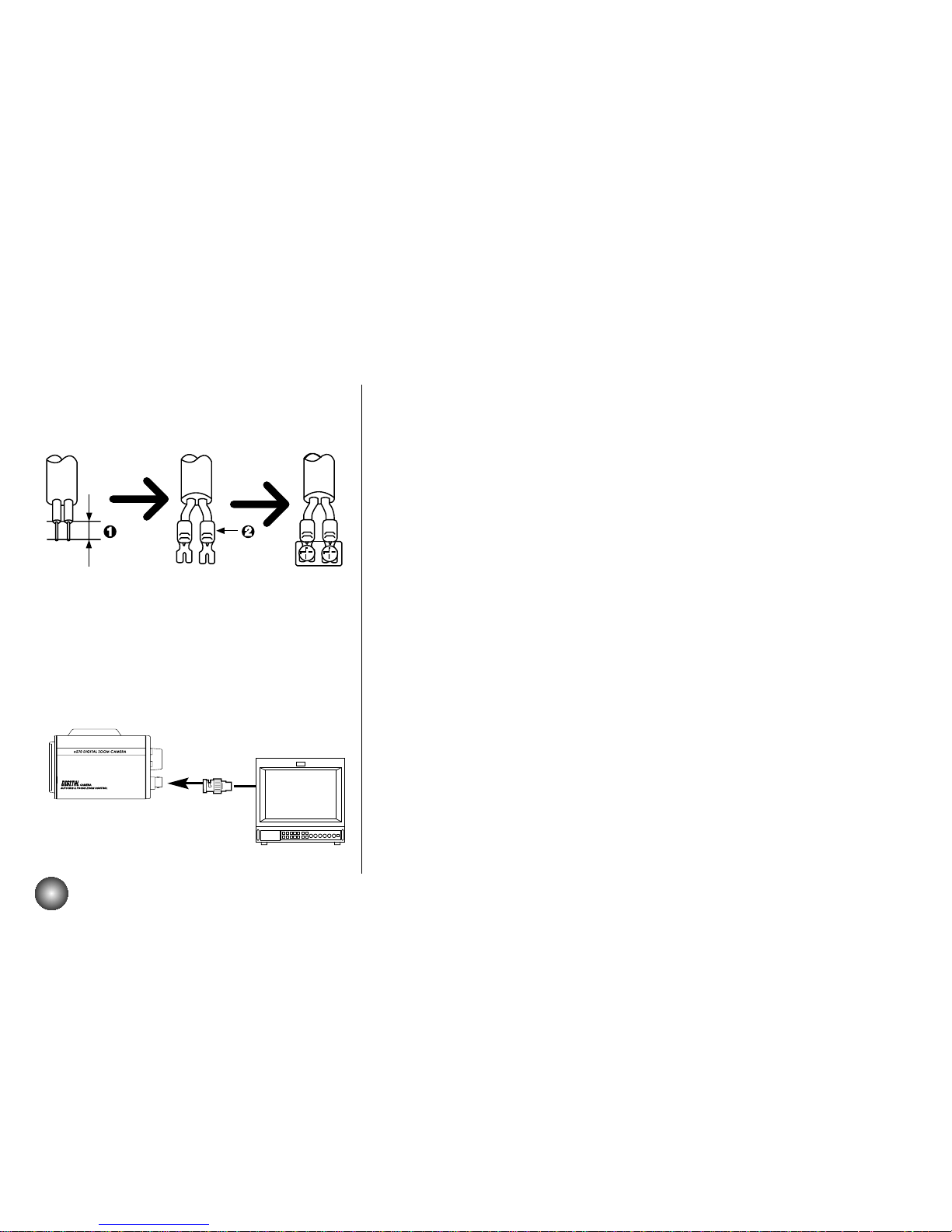
Power Connection
1. Remove the insulation on the power cab le as illustrated.
2. Attach the terminal tips.
3. Connect to the DC 12V terminals on the camera.
Connection the monitor
1. To VIDEO OUT
2. T o Video input on the monitor
Page 7
7
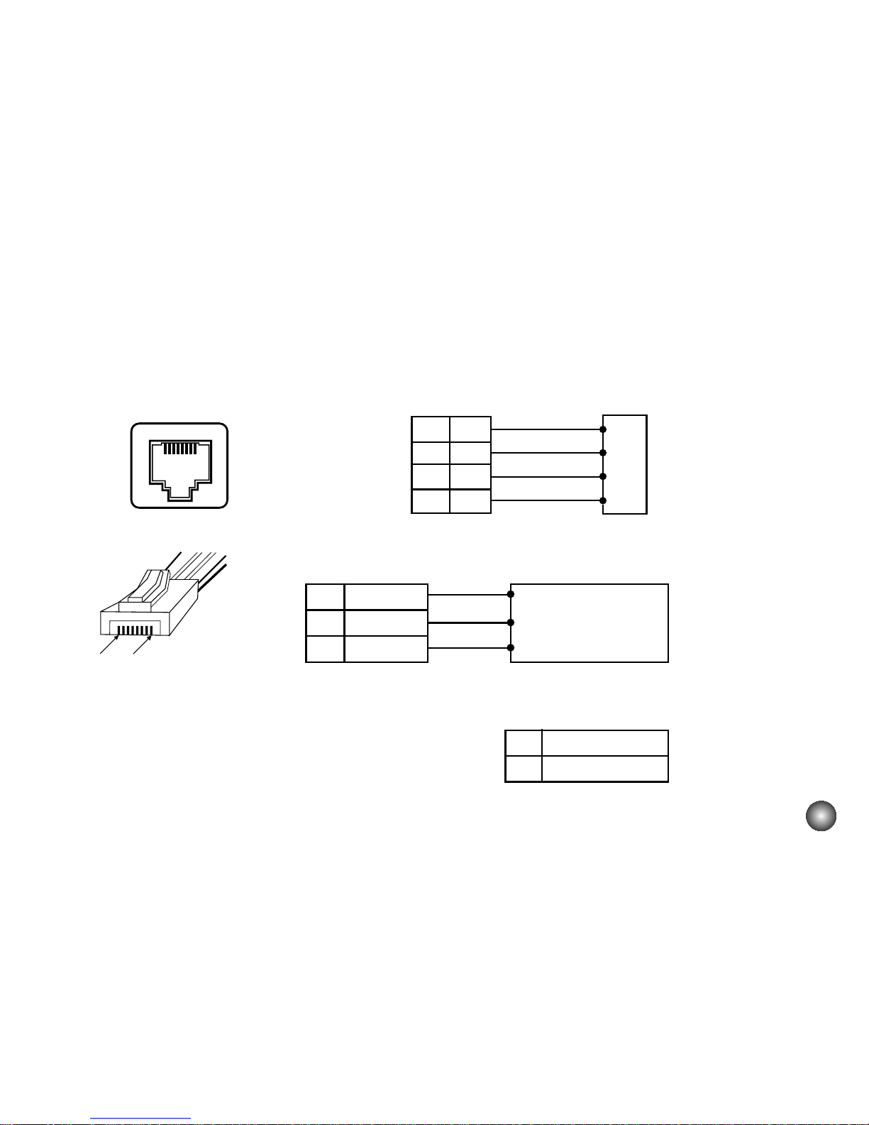
Control
CONTROL
PIN 8 PIN 1
Remote Control Lines are connected to RJ-45 socket as shown below
In case of RS-422 INTERFACE (Basic)
In case of Zoom/Focus control Interface (option)
Receiver/Controller
Voltage Range
1
2
7
8
R+
RTT+
T+
TRR+
CONTROL OUT Controller
4
5
6
ZOOM
COMMON
FOCUS
ZOOM (+Tele, -Wide)
COM
FOCUS (+Near, -Far)
+-Vcom + (+5~15V)
Vcom - (+5~15V)
Page 8
8
page 9page 9
page 10-11page 10-11
page 12-13page 12-13
page 14-16page 14-16
page 17-18page 17-18
page 19page 19
page 20page 20
page 21page 21
page 22page 22
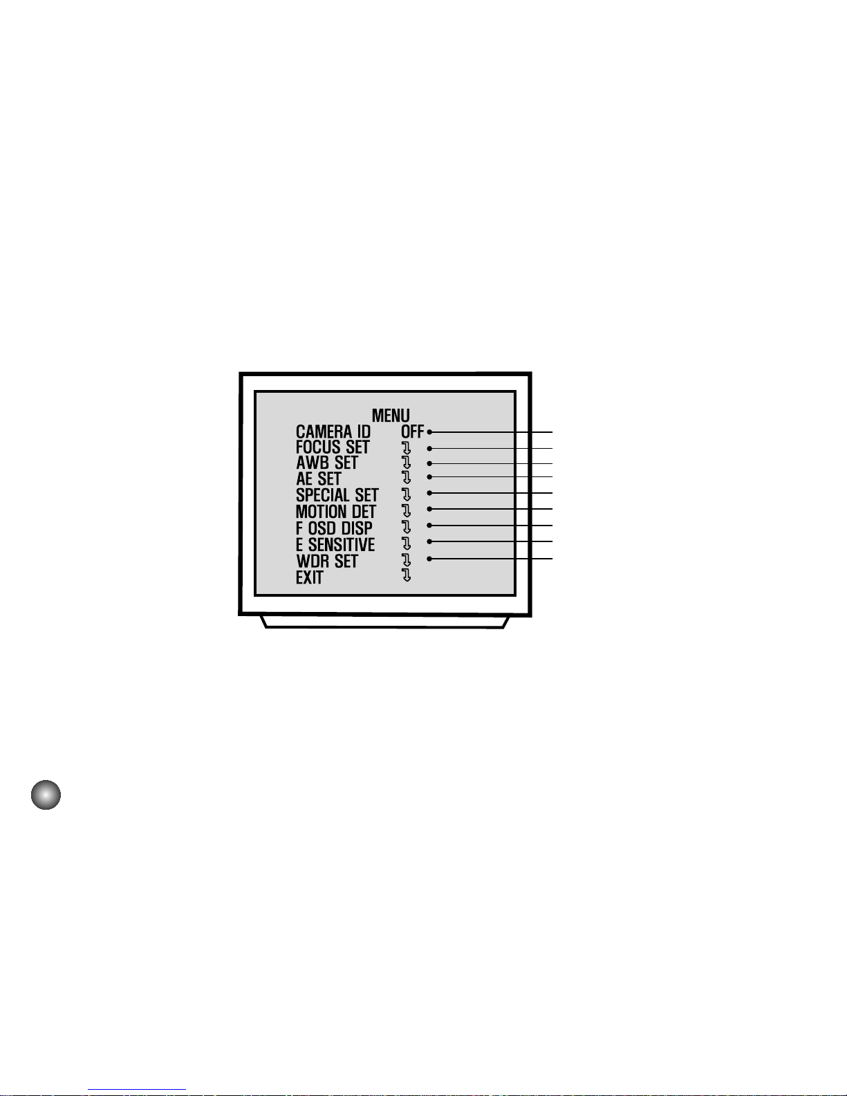
Using TELE, WIDE, FOCUS+, FOCUS- button
• TELE and WIDE are used for UP and DOWN.
• FOCUS+ and FOCUS-are used for INCREASE and DECREASE the data.
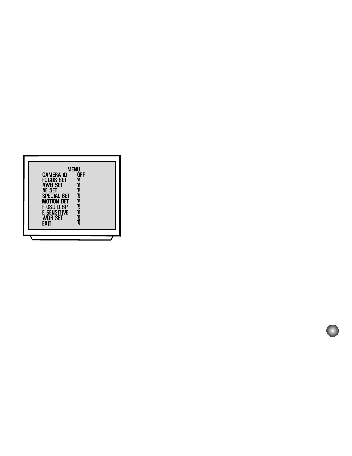
MENU DESCRIPTIONS
Page 9
9
CAMERA ID
1. CAMERA ID
To connect a large number of camera , It can be
assigned to identification number to each camera for
camera control easily. (OFF, 0 - 255 : total numbers of
ID are 256)
• It only can be set this function using ID commend.
To transfer ID Code of camera , In first byte at PC
control. Set the ID number of camera , and then the
ID number display continuously .
Page 10
PUSH
10
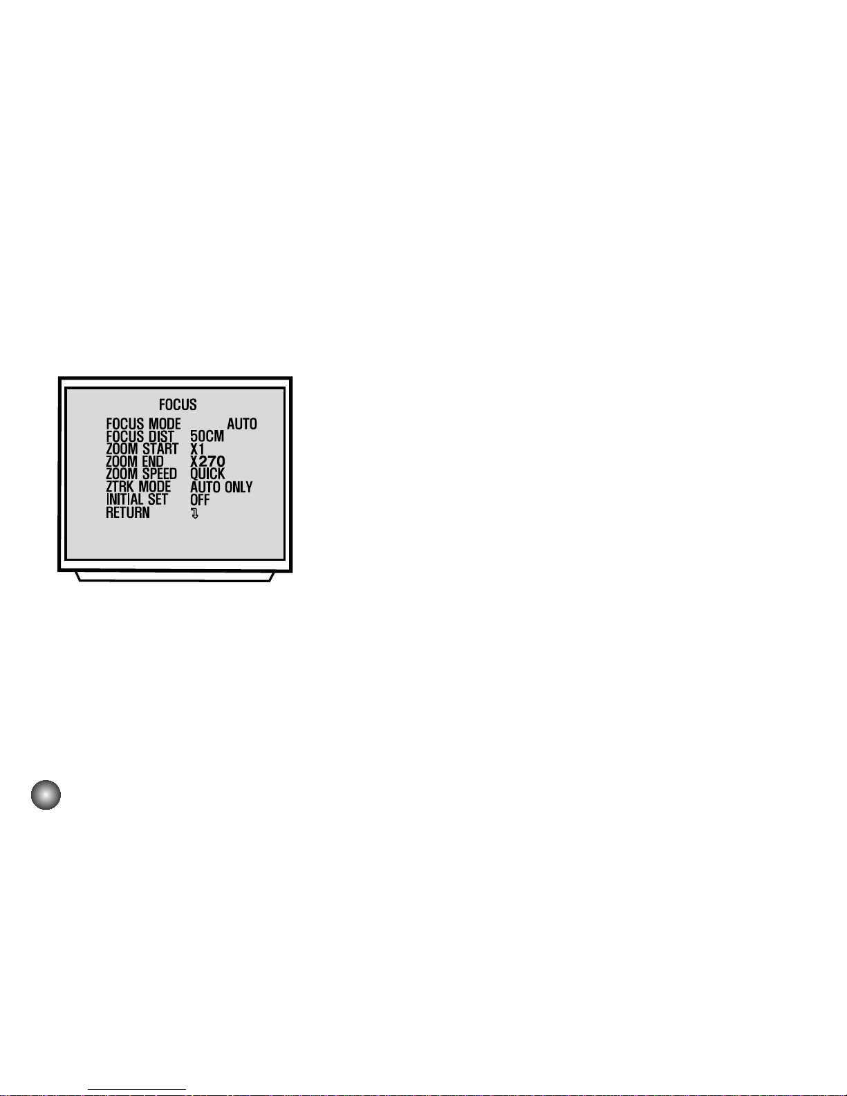
2. Focus Set:
2-1. Focus Mode Set:
This function is for focus mode setting
A) Set up “FOCUS SET” in main menu using Menu key.
Select the “FOCUS MODE” in submenu using
Tele/Wide key. And then set the mode (Auto, Push
auto, or Manual) using Focus key.
2-2. Focus Distance Set:
This function is for selection of minimum shooting
distance.
A) Select the “FOCUS DIST” in submenu using
Tele/wide key.
B) Set the focus distance mode from
1cm to 5M. (1cm, 10cm, 50cm, 1M, 3M, 5M) using
Focus key.
2-3. ZOOM START Set :
This function is for selection of zoom start position.
A) Select the “ZOOM START” in submenu using
Tele/wide key.
B) Set the Zoom start mode from x1
to x27. using Focus key.
Page 11
11
PUSH
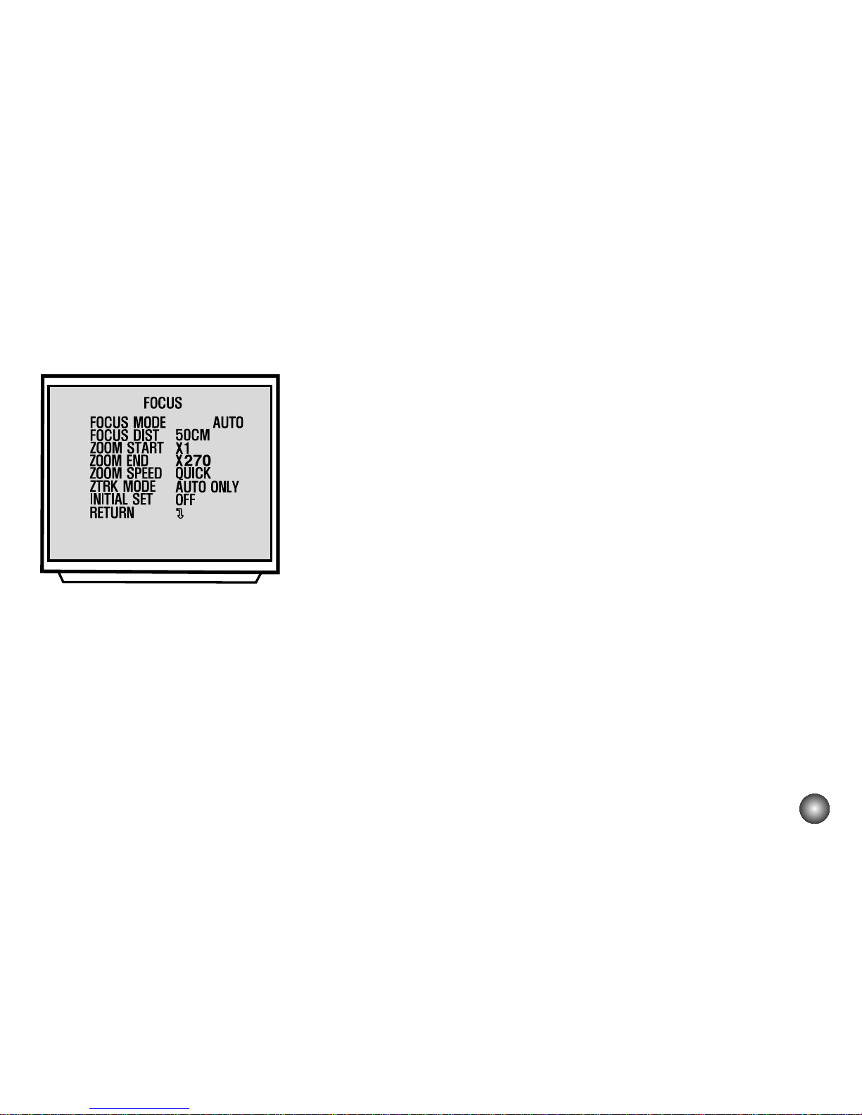
FOCUS MODE SET
2-4. ZOOM END Set:
This function is for selection of zoom end position.
A) Select the “ZOOM END” in submenu using Tele/wide key.
B) Set the Zoom end mode from (Zoom Start + 1) x 270 to X using
Focus key.
2-5. ZOOM SPEED Set:
This function is for selection of zoom speed.
A) Select the “ZOOM SPEED” in submenu using Tele/wide key.
B) Set the Zoom speed, Slow, Middle , Quick using Focus key.
2-6. ZOOM TRACKING MODE Set:
This function is for selection of zoom tracking mode.
A) Select the “ZTRK” in submenu using Tele/wide Command, B) Set
the Zoom tracking mode to Auto or Manual.
* Zoom tracking means focused zooming state.
2-7. INITIAL SET:
If initial mode set to ON, All FOCUS SET function is
changed to the factory setting.
A) Select the “INITIAL SET” in submenu using Tele/wide key. B) Set
the initial set mode to ON or OFF using Focus key.
2-8. RETURN TO MAIN MENU:
This function is exit to main menu.
A) Select the “RETURN” in submenu using Tele/wide key. B) Set the
return mode using Focus key.
Page 12
12
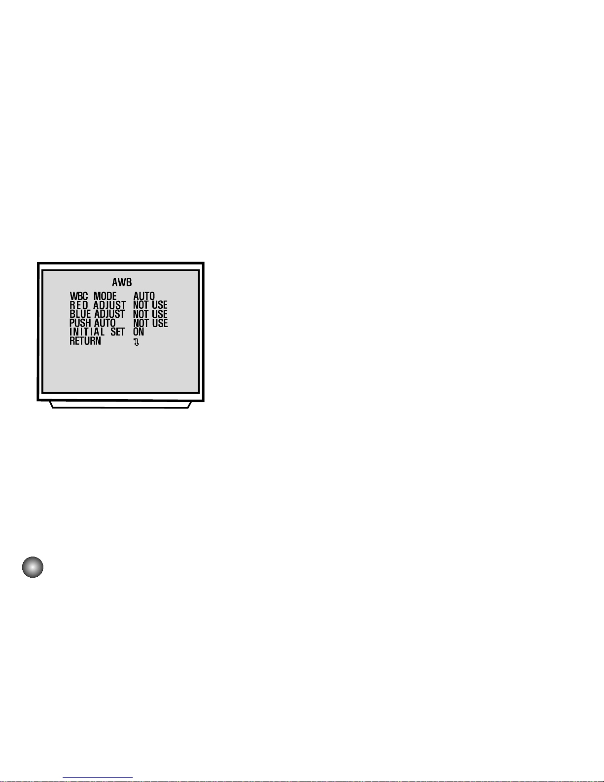
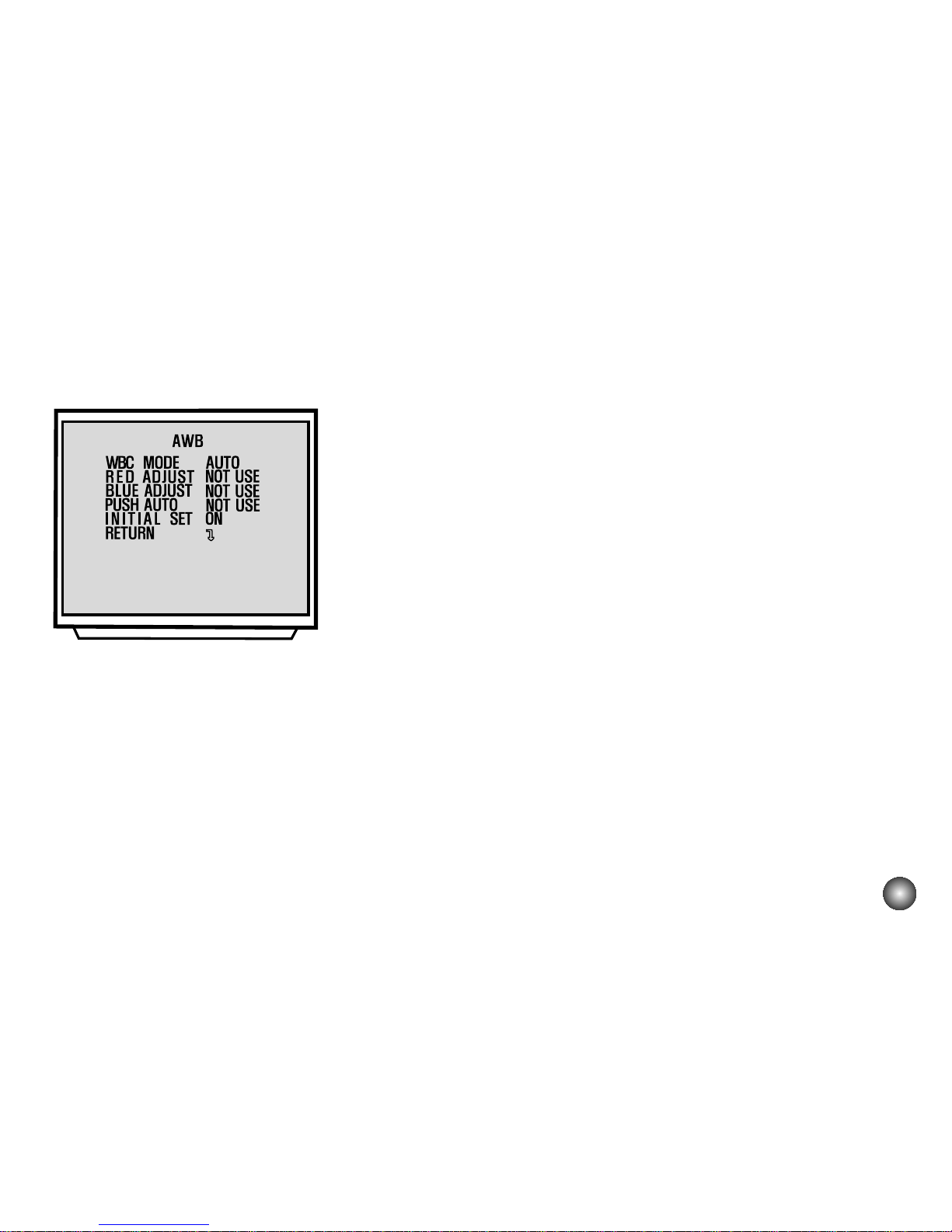
3. AWB SET
3-1. WB Mode Set:
This function is for changing the WB mode.
A) Set up “AWB SET” in main menu using Tele/wide key.
B) Select the “WB MODE” in submenu using Tele/wide key.
C) Set the mode Auto, Push auto , Manual, Outdoor, Indoor,
Special using Focus key.
*WBC MODE ; Use for changing White Balance Mode .
1) AUTO ; WB Range 2800 °K ~ 8000 °K.
2) PUSH AUTO ; Set the AWB mode to Push Auto, then WB Mode is
auto.
3) SPECIAL ; Under the special WB condition( Differ from curve of the
control color temperature ), Adjust Red and Blue to perform a
desired Auto White Balance.
3-2. RED ADJUST Set:
This function is available for Special ,Push Auto, Manual WB mode.
This mode is the adjustment of user option for special color.
A) Select the “RED ADJUST” in submenu using Tele/wide key.
B) Adjust the level from (-30 to 30 SPECIAL, -128 to +127 PUSH AUTO,
0-255 MANUAL) using Focus key.
AWB SET
Page 13
13
3-3. BLUE ADJUST Set :
This function is available for Special ,Push Auto, Manual WB mode.
This mode is the adjustment of user option for special color.
A) Select the “BLUE ADJUST” in submenu using Tele/wide key.
B) Adjust the level from (-30 to 30 SPECIAL, -128 to +127 PUSH AUTO,
0-255 MANUAL) using Focus key.
3-4. PUSH AUTO :
In case of PUSH AUTO WB mode.
Adjust the push auto mode ON, WB act automatically.
3-5. INITIAL SET :
If initial mode set to ON, All AWB function is changed
to the factory setting
A) Select the “INITIAL SET” in submenu using Tele/wide key.
B) Set the initial set mode to ON or OFF using Focus key.
3-6. RETURN TO MAIN MENU :
This function is exit to main menu.
A) Select the “RETURN “ in submenu. Using Tele/wide key.
B) Set the return mode using Focus key.
AWB SET
Page 14
14
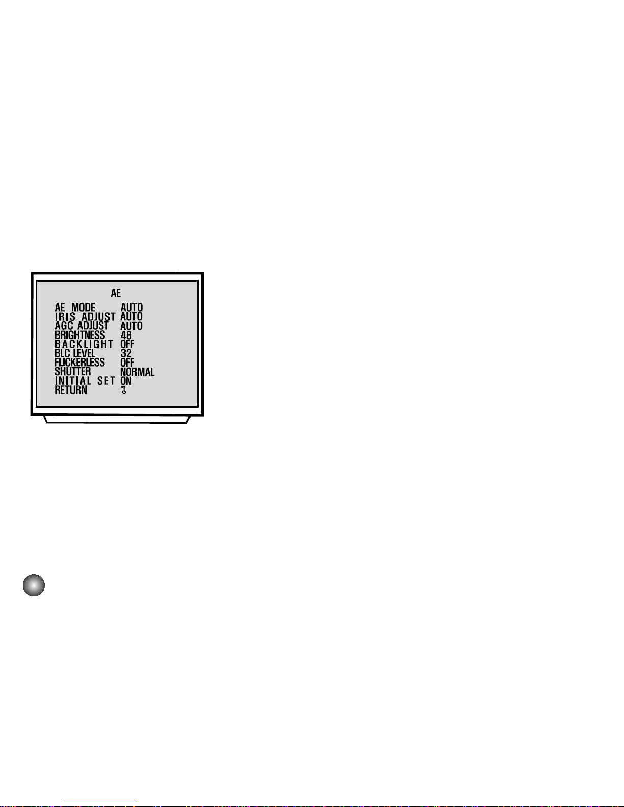
4. AE SET
4-1. AE Mode Set:
This function is for changing to AE mode.
A) Set up “AE SET” in main menu using Tele/wide key.
B) Select the “AE MODE” in submenu using Tele/wide key.
C) Set the mode auto, IRIS MAN, AGC MAN, Manual, Auto using
Focus key.
4-2. IRIS ADJUST Set:
This function is available for IRIS MAN mode.
A) Select the “IRIS ADJUST” in submenu using Tele/wide key. B) Adjust
the level from ##MIN to ##MAX(MANUAL, IRIS MAN) using Focus
key.
* ## : Current level at Auto mode.
4-3. AGC ADJUST Set :
This function is available for AGC MAN mode.
A) Select the “IRIS ADJUST” in submenu using Tele/wide key. B) Adjust
the level from ##MIN to ##MAX(MANUAL, AGC MAN) using Focus
key.
* ## : Current level at Auto mode.
AE SET
Page 15
15
Area1
Area1
Area1
Area1
Area1
Auto BLC
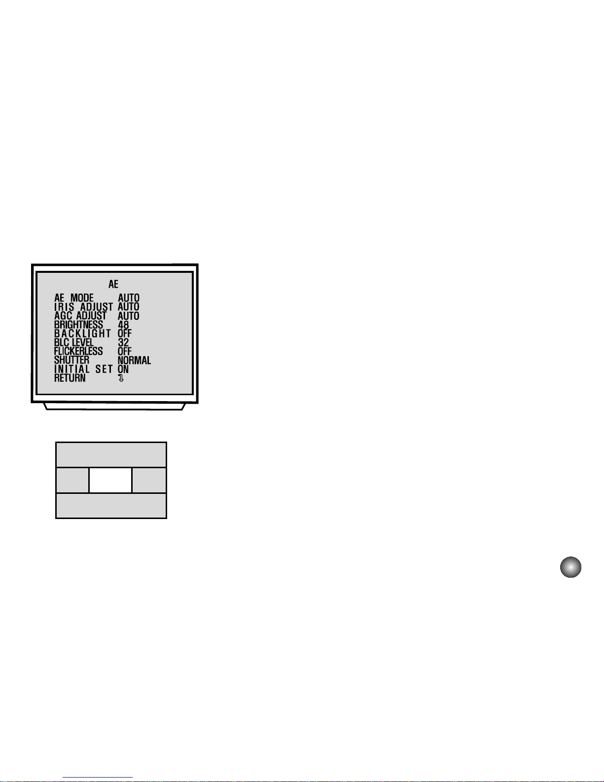
AE SET
4-4. BRIGHTNESS ADJUSTMENT Set:
A) Select the “BRIGHTNESS” in submenu using Tele/wide key. B) Adjust
the level from ##MIN to ##MAX. using Focus key.
* ## : Current level at Auto mode.
4-5. BACKLIGHT Set:
A) Select the “BACKLIGHT” in submenu using Tele/wide key.
B) Set the mode OFF, ON, or AUTO using Focus key.
* Auto BLC (Auto back light compensation)
When a back light condition occurs in area1,area2, area3, or
area4. the back light compensation is enable. When the back light
condition disappears in that area, BLC is disable automatically. If
do not want this mode, set to OFF
4-6. FLICKERLESS Set:
A) Select the “FLICKERLESS” in submenu using Tele/wide key.
B) Set the mode OFF, ON using Focus key.
* FLICKERLESS ; Use for removing the flicker of picture
ON : Remove the flicker ( In case of PAL System ;
Shutter Speed 1/120 sec ).
Page 16

16
4-7. SHUTTER SPEED Set:
A) Select the “SHUTTER” in submenu using Tele/wide key.
B) Set the mode NORMAL, 1/125 - 1/10000 using Focus key.
4-8. INITIAL SET:
A) Select the “INITIAL SET” in submenu using Tele/wide
Command,
B) Set the initial set mode to ON or OFF using Focus key.
4-9. RETURN TO MAIN MENU:
This function is exit to main menu.
A) Select the “RETURN “ in submenu using Tele/wide key.
B) Set the return mode using Focus key.
AE SET
Page 17
17
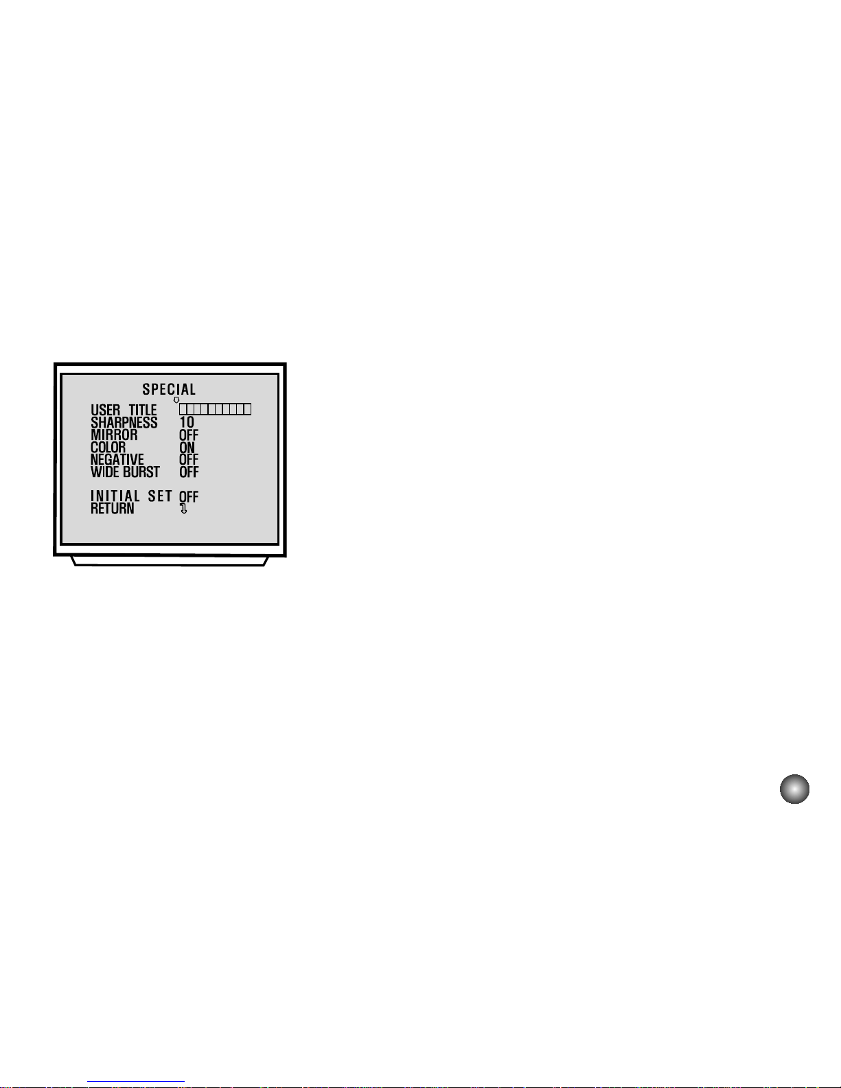
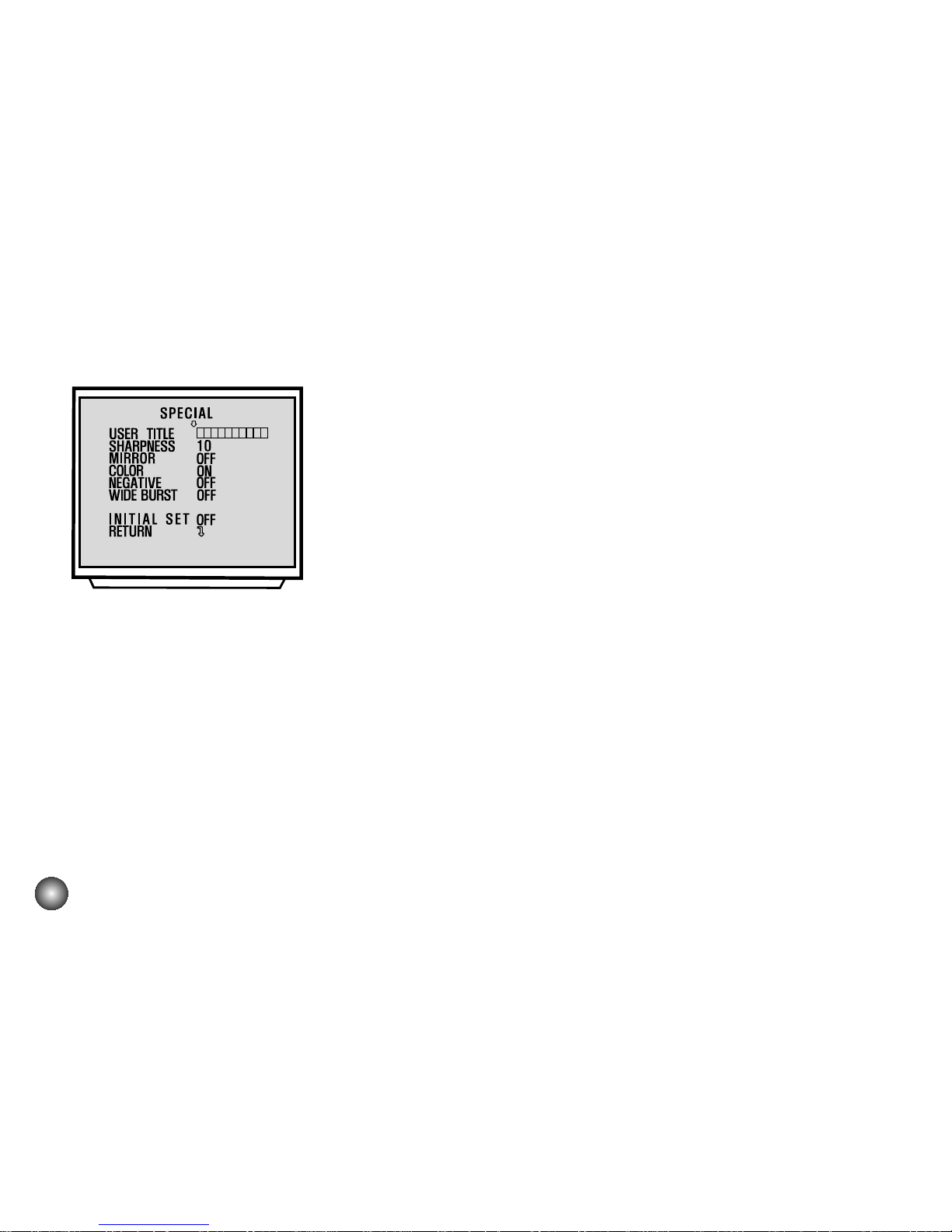
SPECIAL SET
5. SPECIAL SET
5-1. User Title Set:
This function is for custom title on screen display.
A) Set “SPECIAL SET” in main menu using Tele/wide key.
B) Select the “USER TITLE” in submenu using Tele/wide key.
C) Set the position of title and set data using Tele / Wide,
Focus key.
5-2. SHARPNESS ADJUST Set:
A) Select the “SHARPNESS” in submenu using Tele/wide key.
B) Adjust the level from 0 to 15 using Focus key.
5-3. MIRROR Set:
A) Select the “MIRROR” in submenu using Tele/wide key.
B) Select the mode ON, OFF using Focus key.
5-4. COLOR Set:
This mode is for B/W mode.
A) Select the “COLOR” in submenu using Tele/wide key. B) Select the
mode ON, OFF using Focus key.
Page 18
18
SPECIAL SET
5-5. NEGATIVE Set:
This mode is to change color and luminance to negative.
A) Select the “COLOR” in submenu using Tele/wide key.
B) Select the mode ON, OFF using Focus key.
5-6. WIDE BURST Set:
This mode is to change color burst width for long distance application.
A) Select the “WIDEBURST” in submenu using Tele/wide key.
B) Select the mode ON, OFF using Focus key.
5-7. LANGUAGE SET:
A) ENG / CHI : English / Chinese language select
B) BLANK : English Only
5-8. INITIAL SET: If initial mode set to ON, All SPECIAL functions are
changed to the factory setting
A) Select the “INITIAL SET” in submenu using Tele/wide key.
B) Set the initial set mode to ON or OFF Using Focus key.
5-9. RETURN TO MAIN MENU:
This function is exit to main menu.
A) Select the “RETURN” in submenu using Tele/wide key.
B) Set the return mode Using Focus key.
Page 19
19
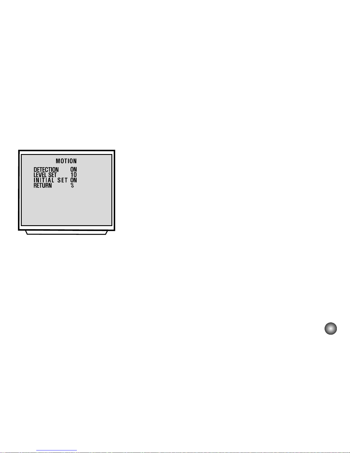
MOTION DET
6. MOTION DETECTION SET
6-1. DETECTION Mode Set:
A) Set “MOTION” in main menu using Tele/wide key.
B) Select the “DETECTION” in submenu. Using Tele/wide key.
C) Set the mode ON, OFF using Focus key.
6-2. LEVEL ADJUST Set:
This function is available for DETECTION ON mode.
A) Select the “LEVEL SET” in submenu. Using Tele/wide key.
B) Adjust the level to some sensitivity using Focus key.
6-3. INITIAL SET:
If initial mode set to ON, All MOTION functions are changed to the
factory setting
A) Select the “INITIAL SET” in submenu using Tele/wide key.
B) Set the initial set mode to ON or OFF Using Focus key.
6-4. RETURN TO MAIN MENU:
This function is exit to main menu.
A) Select the “RETURN” in submenu using Tele/wide key.
B) Set the return mode Using Focus key.
Page 20

20
F. OSD SET
7-1. FUNCTION Set:
A) Set “F. OSD” in main menu using Tele/wide key.
B) Select the mode what you want in submenu using Tele/wide key.
C) Set the display mode of OSD using Tele / Wide, Near/Far key.
*INITIAL SET and RETURN are the same as before procedure.
Page 21

21
8. E. SENSITIVITY SET
8-1. E. SENSITIVITY SET
A) Select the “E.SENSITIVITY” in submenu using Tele/wide key.
B) Select the sensitivity mode what you want in submenu using
Focus key.
*Mode sequence: OFF-X2 AUTO-X4 AUTO-X8 AUTO-X10
AUTO-X16 AUTO- X32 AUTO -OFF- X2 FIX-X4 FIX -X8
FIX -X10 FIX -X16 FIX - X32 FIX-OFF
8-2. INITIAL SET: If initial mode set to ON, E.SENSITITY functions are
changed to the factory setting
A) Select the “INITIAL SET” in submenu using Tele/wide key.
B) Set the initial set mode to ON or OFF Using Focus key.
8-3. RETURN TO MAIN MENU : This function is exit to main menu.
A) Select the “RETURN” in submenu using Tele/wide key.
B) Set the return mode Using Focus key.
E. SENSITIVITY SET
Page 22

WDR
22
WDR SET
9. WDR SET
9-1. WDR SET
A) Select the “WDR” in main menu using Tele/wide key.
B) Select the “WDR CONTROL” in submenu using Tele/wide key.
C) Select the WDR mode what you want in submenu using Focus
key.
* Mode sequence : OFF -- ON -- AUTO
* WDR Auto mode is working at the condition of
high lightback light.
9-2. LEVEL ADJUST Set:
This function is the gain adjustment of WDR
A) Select the “SENSITIVITY” in submenu using Tele/wide key.
B) Adjust the level to some sensitivity using Focus key.
9-3. INITIAL SET:
If initial mode set to ON, All WDR functions are changed to the
factory setting
A) Select the “INITIAL SET” in submenu using Tele/wide key.
B) Set the initial set mode to ON or OFF Using Focus key.
9-4. RETURN TO MAIN MENU:
This function is exit to main menu.
A) Select the “RETURN” in submenu using Tele/wide key.
B) Set the return mode Using Focus key.
Page 23

23
On Screen Display
STAND BY
1 2
3 6
5
7 4
Some of these functions will
be displayed every time the
camera is operated and then
disappeared after 5 seconds.
.
.
.
.
FUNCTION
OSD
Format
Description
1. Focus Mode Non display Auto Mode
Manual / push Auto Mode
2. Back Light Non display Back Light OFF
“BL”display BLC ON / Auto BLC Mode
3. Shutter Speed Non display Normal Shutter ( PAL: 1/50)
“Ff”display Flickerless Mode
1/125 28 variable steps.
1/10,000
4. STAND-BY Indicate the camera stand-by during the
camera’s power turning ON.
5. CAMERA ID
According to write the identification number
to each camera, Multi-point control is
available
(PC Control 000~255).
Page 24

FUNCTION OSD Format Description
24
White Balance AUTO
Special Auto White Balance; Adjustment Mode according to
change of external illuminant. RED ADJUST and BLUE
ADJUST (0~255) are available. After changing R/B value, The
mainternance mode is “AUTO”.
WB Preset for INDOOR (3200°K)
Wb Preset for OUTDOOR (5100°K)
Manual WB Adjustment; In manual mode the HUE control is
available (0 ~ 99).
Push Auto White Balance; Turn this mode ON, the white trace
automatically. Turn this mode OFF, preserve the white of final
auto tracing action (Manual).
Digital Zoom mode
Optical Zoom mode
DX 270
X 27
7. ZOOM Display
6. WBC Mode
P
W
M
W
S
W
On Screen Display
Page 25

25
Image device
Sync system
Horizontal resolution
Lens
Digital Zoom Ratio
Minimum illumination
S/N
Scanning System
Scanning Frequency(H)
Scanning Frequency(V)
Specifications
Image device 1/4" interline transfer CCD
NTSC, High resolution : 811(H) X 508(V) 410K
NTSC, Normal resolution : 537(H) X 505(V) 270K
PAL, High resolution : 795 (H) X 596 (V) 470K
PAL, Normal resolution : 537(H) X 597(V) 320K
Internal
Approx.480 Line (NTSC, High resolution)
320 Line (NTSC, Normal resolution)
470 Line (PAL, High resolution)
320 Line (PAL, Normal resolution)
(at center of screen)
X 27 Zoom (F 1.5 (W), F 3.8 (T) f= 3.25 ~ 88.0 mm)
X 10 (Total Zoom Ratio X 270)
Normal Mode : 1 Lux (1/3 Video Output)
Electronic Shutter Speed Mode :
0.01 Lux (X32 Field Accumulate)
Night Mode : 0 Lux (Infrared ON)
More than 48dB
2:1 Interlace
15.734 kHz (NTSC), 15.625 kHz (PAL)
59.94Hz (NTSC), 50Hz (PAL)
Page 26

OSD(On Screen Display)
Power requirement
Video output
Power consumption
operating temperature
Operating Humidity
Storage temperature
Dimensions
Weight
Specifications are subject to change without notice.
26
Specifications
English
DC 9V-15V
Composite Output 75S Terminated
5.3W
0°C - 45°C
0% RH - 60% RH
-20°C - 60°C, 0% RH - 85% RH
57mm(W) X 68.9mm(H) X 111.5mm(D)
500g
Page 27

27
RS-422/RS-485 Command
1. Communication Format
1. Connection Conditions>
Data Length 1 Byte ( 8 Bit )
Start/Stop Bit 1 BIT
Parity Bit None
Baud rate 9,600 bps
2. The communication data format from PC to Camera
The data of total 6 bytes is transmitted PC to camera.
1) Format:
BYTE 1 BYTE 2 BYTE 3 BYTE 4 BYTE 5 BYTE 6
0xC5 CODE1 CODE2 CODE3 CAM_ID C.S
2) Description: a) BYTE 1 : Camera is realized the protocol comes from PC.
b) BYTE 2 : The changed data accounting to PC Command. (Refer to 10-2. PC Command)
c) BYTE 3 : The changed data accounting to PC Command.(Refer to 10-2. PC Command)
d) BYTE 4 : The changed data accounting to PC Command.(Refer to 10-2. PC Command)
e) BYTE 5 : Camera's ID(identification) number to Communicate (0~255).
In case of difference between this value of CAM_ID and given value of
Camera's ID, It is impossible to communicate wide.
f) BYTE 6 : The value of Check Sum from 'BYTE 1' to 'BYTE 5'.
0xC5 + 0x5F + 0x02 + 0x00 + 0x0A = 0x0130
therefore, C S = 0x30
Page 28

28
3. The communication data format from Camera to PC
2) Description: a) BYTE 1 : Camera is realized the protocol comes from PC.
b) BYTE 2 : BYTE 1 data is received from PC.
c) BYTE 3 : BYTE 2 data is received from PC.
d) BYTE 4 : BYTE 3 data is received from PC.
e) BYTE 5 : The changed data according to PC Command.( Refer to 10-2. PC Command)
f) BYTE 6 : The changed data according to PC Command.( Refer to 10-2. PC Command)
g) BYTE 7 : The changed data according to PC Command.( Refer to 10-2. PC Command)
h) BYTE 8 : The changed data according to PC Command.( Refer to 10-2. PC Command)
i) BYTE 9 : The value of Check Sum from 'BYTE 1' to 'BYTE 8'.
The computing method is the same of “BYTE6 of the communication from
PC to Camera”
The data of total 6 bytes is transmitted camera to pc.
1) Format
BYTE 1 BYTE 2 BYTE 3 BYTE 4 BYTE 5 BYTE 6 BYTE 7 BYTE 8 BYTE 9
0xC5 CODE1 CODE2 CODE3 DATA1 DATA2 DATA3 DATA4 C S
Page 29

29
2. PC Command
1. Read Camera ID
This command is to read the ID number on camera that is currently connected.
Caution This command is valid only one camera is connected.
Control Command
[C5h] [CCh] [00h] [00h] [XXh] [Check Sum]
Return Data
[C5h] [CCh] [00h] [00h] [Camera ID] [Check Mode] [XXh] [XXh] [Check Sum]
Parameter Description
* Camera ID -> Means the assigned "Camera ID" on camera that is connected with controller.
Data Range: 00h(0d) ~ FFh(255d)
* Check Mode -> Means ON/OFF mode by the inspection of camera ID number when it is controlled by
remote.
* XXh -> Means "Don't care data" and declared "XXh".
Check Mode Description
•Camera is "Camera ID Number Check Off Mode".
00h •In this case Remote Control is possible at the Works differently camera ID
number between Controller and Camera (Only possible under 1 to 1 controlling).
•Camera is "Camera ID Number Check On Mode".
FFh •In this case Remote Control
is possible at the same camera ID number between Controller and Camera.
Page 30

30
2. Change Camera ID
2. Change Camera ID
This command is to change the camera ID number which is connected as New ID number or
Enable or Disable a "Camera ID Number Check Mode".
Control Command
[C5h] [78h] [New Camera ID] [Check Mode] [Camera ID] [Check Sum]
Return Data
[C5h] [78h] [New Camera ID] [Check Mode] [New Camera ID] [XXh] [XXh] [XXh] [Check Sum]
Parameter Description
* Camera ID -> Assigned Camera ID that is controlled by remote.
* New Camera ID -> New ID that you try to change.
Possible ID change range is from "0d(00h)" to "255d(FFh)".
* Check Mode -> Setup On/Off of camera ID number inspection in case of remote controlling.
Check Mode Description
00h Set the camera to "Camera ID Number Check Off Mode". Here the new camera
ID will be ignored.
Other Values Set the camera to "Camera ID Number Check On Mode". Here the camera ID
is changed to New Camera ID.
Page 31

31
3. Camera ID Display ON/OFF control
0xC5 0xAA 0x96 Mode CAM_ID C·S
0xC5 0xAA 0x96 Mode 0x96 0xXX 0xXX 0xXX C·S
0xC5 0x4F 0x00 0x00 CAM_ID C·S
0xC5 0x4F 0x00 0x00 0x00 0xXX 0xXX 0xXX C·S
Change the Camera ID display mode of camera according to the data “Mode”.
1) PC -> Camera
2) Camera -> PC
mode :: This is a data for setting the Camera ID Display Mode.
In case of Mode = 0x01, the Camera ID number is displayed on the screen (Display ON mode).
In case of Mode = 0x00, the Camera ID number is not displayed on the screen (Display OFF mode).
Otherwise, The Camera ID Display mode is not changed.
Caution:If the Camera ID is 0x00, then the Camera ID is displayed on the screen at any time.
4. Camera Restart
; Restart the Camera.
1) PC -> Camera
Page 32

32
5. Camera Power Off; Turn off power of Camera.
6. Camera Power ON; Turn on the power of Camera.
0xC5 0x3E 0x00 0x00 CAM_ID C·S
0xC5 0x3E 0x00 0x00 0x00 0xXX 0xXX 0xXX C·S
Change the Camera ID display mode of camera according to the data “Mode”.
1) PC -> Camera
2) Camera -> PC
0xC5 0x3A 0x00 0x00 CAM_ID C·S
0xC5 0x3A 0x00 0x00 0x00 0x00 0xXX 0xXX C·S
1) PC -> Camera
2) Camera -> PC
Page 33

33
7. MENU OSD Display ON/OFF Setting
8. Camera Initialization
0xC5 0xAA 0x63 MODE CAM_ID C·S
0xC5 0xAA 0x63 MODE 0x63 0xXX 0xXX 0xXX C·S
0xC5 0x6F 0x00 0x00 CAM_ID C·S
0xC5 0x6F 0x00 0x00 0x00 0xXX 0xXX 0xXX C·S
Set the MENU OSD Display mode of the camera to ON or OFF according to the data of “MODE”.
1) PC -> Camera
2) Camera -> PC
MODE: In case of MODE = 0x01, MENU OSD Display mode is changed to ON mode .
In case of MODE = 0x00, MENU OSD Display mode is changed to OFF mode
Otherwise, MENU OSD Display mode is not changed.
Initialize all setting states of the camera.
1) PC -> Camera
2) Camera -> PC
Page 34

34
9. BACKLIGHT ON/OFF control
0xC5 0xAA 0x70 MODE CAM_ID C S
0xC5 0xAA 0x70 MODE 0x70 0xXX 0xXX 0xXX C S
Switch the BACKLIGHT mode to ON/OFF according to the data of “MODE”.
1) PC -> Camera
MODE: In case of MODE = 0x01, MENU OSD Display mode is changed to ON mode .
In case of MODE = 0x00, MENU OSD Display mode is changed to OFF mode
Otherwise, MENU OSD Display mode is not changed.
10. COLOR ON/OFF control
Switch the COLOR mode to ON/OFF according to the data of “MODE”.
1) PC -> Camera
2) Camera -> PC
2) Camera -> PC
0xC5 0xAA 0x71 MODE CAM_ID C S
0xC5 0xAA 0x71 MODE 0x71 0xXX 0xXX 0xXX C S
MODE: In case of MODE = 0x01, The BACKLIGHT mode becomes ON mode.
In case of MODE = 0x00, The BACKLIGHT mode becomes OFFmode.
Otherwise, The BACKLIGHT mode is not changed.
Page 35

35
11. 100% NEGATIVE ON/OFF control
0xC5 0xAA 0x72 MODE CAM_ID C S
0xC5 0xAA 0x72 MODE 0x72 0xXX 0xXX 0xXX C S
Switch the 100% NEGATIVE mode to ON/OFF according to data of “MODE”.
1) PC -> Camera
2) Camera -> PC
MODE: In case of MODE = 0x01, The 100% NEGA TIVE mode becomes ON mode .
In case of MODE = 0x00, The 100% NEGATIVE mode becomes OFFmode.
Otherwise, The 100% NEGA TIVE mode is not changed.
12. FOCUS Mode Setting
Change "Focus Action Mode" of the connected camera.
Control Command
[C5h] [AAh] [73h] [Focus Mode] [Camera ID] [Check Sum]
Return Data
[C5h] [AAh] [73h] [Focus Mode] [73h] [XXh] [XXh] [XXh] [Check Sum]
Parameter Description
*Focus Mode -> Means data to indicate "Focus Operation Mode".
"Focus Action Mode" according to each data are, as followings.
Page 36

36
Focus Mode
01h
00h
02h
Other V alues
• Set "Focus Action Mode" to "Focus Auto/Manual A UTO Mode".
• Camera Fulfill "Auto F ocus Action".
• If "Focus Auto/Manual Or Push Auto" k ey is inputted, "Focus Action
Mode" is changed to "F ocus Auto/Manual MANUAL Mode".
• Set "Focus Action Mode" to "Focus Auto Manual MANU AL Mode".
• Camera Fulfill "Manual Focus Action".
• If "Focus A uto/Manual Or Push Auto" key is inputted, "F ocus Action
Mode" is changed to "Focus Auto/Manual A UTO Mode".
• Set "Focus Action Mode" to "Focus PUSH A UTO Mode".
• Camera Fulfill "Manual Focus Action".
• While "F ocus Auto/Manual Or Push Auto" ke y is inputted, "Auto Focus"
is Fulfilled.
• Ignored.
Description
Page 37

37
13. FLICKERLESS Mode ON/OFF Setting
0xC5 0xAA 0x74 MODE CAM_ID C S
0xC5 0xAA 0x74 MODE 0xXXX 0xXX 0xXX 0xXX C S
Switch the FLICKERLESS mode to ON/OFF according to the data of “MODE”
1) PC -> Camera
2) Camera -> PC
MODE: In case of MODE = 0x01, The FLICKERLESS mode becomes “ON” mode .
In case of MODE = 0x00, The FLICKERLESS mode becomes “OFF”mode.
Otherwise, The FLICKERLESS mode is not changed.
0xC5 0xAA 0x66 WB_CNT CAM_ID C S
0xC5 0xAA 0x65 WB_CNT 0x65 0xXX 0xXX 0xXX C S
Set the mode of White Balance according to WB_CNT.
1) PC -> Camera
2) Camera -> PC
MODE: This is a counter to change the mode of White Balance 1.
In case of WB_CNT= 0, the mode of White Balance becomes a “AUT O” mode. 2.
In case of WB_CNT= 1, the mode of White Balance becomes a “SPECIAL ” mode. 3.
In case of WB_CNT= 2, the mode of White Balance becomes a “INDOOR” mode. 4.
In case of WB_CNT= 3, the mode of White Balance becomes a “OUTDOOR” mode. 5.
In case of WB_CNT= 4, the mode of White Balance becomes a “PUSH AUT O” mode.
14. White Balance Mode Set Command
Page 38

38
15. SPECIAL White Balance Mode RED adjust data Setting
0xC5 0xAA 0x75 RED_ADJ CAM_ID C S
0xC5 0xAA 0x75 RED_ADJ 0x75 0xXX 0xXX 0xXX C S
Set the RED adjust data at SPECIAL White Balance mode according to the data of “RED_ADJ”.
1) PC -> Camera
2) Camera -> PC
RED_ADJ ; This is a data for which adjusts a RED point at the Special White Balance mode .
data value setting :
Decimal data : -3 -2 -1 0 +1 +2 +3
RED_ADJ data : 0xFD 0xFE 0xFF 0x00 0x01 0x02 0x03
0xC5 0xAA 0x67 BLUE_ADJ CAM_ID C S
0xC5 0xAA 0x76 BLUE_ADJ 0x76 0xXX 0xXX 0xXX C S
Set the BLUE adjust data at SPECIAL White Balance mode according to the data of “BLUE_ADJ”.
1) PC -> Camera
2) Camera -> PC
BLUE_ADJ ; This is a data for which adjusts a BLUE point at the Special White Balance mode .
data value setting :
Decimal data : -3 -2 -1 0 +1 +2 +3
BLUE_ADJ data : 0xFD 0xFE 0xFF 0x00 0x01 0x02 0x03
16. SPECIAL White Balance Mode BLUE adjust data Setting
Page 39

39
17. Set Manual Red Gain
This commands is to set the value of Red Gain in "MANUAL White Balance Control Mode" or "PUSH AUTO
White Balance Control Mode".
Caution It is valid when White Balance Control Mode is "MANUAL White Balance Control Mode"
or "PUSH AUTO White Balance Control Mode".
Control Command
[C5h] [AAh] [A4h] [Red Gain] [Camera ID] [Check Sum]
Return Data
[C5h] [AAh] [A4h] [Red Gain] [A4h] [XXh] [XXh] [XXh] [Check Sum]
Parameter Description
* Red Gain -> Means data to indicate value of Red Gain Control has range
from "00h(Min)" ~ "FFh(Max)".
18. Set Manual Blue Gain
This commands is to set the value of Blue Gain in "MANUAL White Balance Control Mode"
or "PUSH AUTO White Balance Control Mode".
Caution It is valid when White Balance Control Mode is "MANUAL White Balance Control Mode"
or "PUSH AUTO White Balance Control Mode".
Control Command
[C5h] [AAh] [A6h] [Blue Gain] [Camera ID] [Check Sum]
Return Data
[C5h] [AAh] [A6h] [Blue Gain] [A4h] [XXh] [XXh] [XXh] [Check Sum]
Parameter Description
* Blue Gain -> Means data to indicate value of Blue Gain Control has range
from "00h(Min)" ~ "FFh(Max)".
Page 40

40
19. White Balance PUSH_AUTO ON/OFF Setting
0xC5 0xAA 0x78 MODE CAM_ID C S
0xC5 0xAA 0x78 MODE 0x78 0xXX 0xXX 0xXX C S
Switch the PUSH AUTO White Balance state to ON or OFF White Balance mode
according to the data of “MODE”.
1) PC -> Camera
2) Camera -> PC
MODE :: In case of MODE = 0x01, The PUSH AUTO White Balance state becomes to ON.
In case of MODE = 0x00, The PUSH AUTO White Balance state becomes to OFF.
Otherwise, The PUSH AUTO White Balance state is not changed.
Caution :: This mode is not saved when the power of a camera turns OFF/ON.
Default mode is “OFF” mode.
0xC5 0xAA 0x79 Sharpness CAM_ID C S
0xC5 0xAA 0x79 Sharpness 0x79 0xXX 0xXX 0xXX C S
Set the sharpness level of the camera according to the data of “sharpness”.
1) PC -> Camera
2) Camera -> PC
Sharpness ; This is a data for which adjusts a sharpness level of the camera.
Data V alue range :: 00d ~ 15d
20. SHARPNESS Data Setting
Page 41

41
21. BRIGHTNESS Data Setting
0xC5 0xAA END 0x00 CAM_ID C S
0xC5 0x62 END 0x00 END 0xXX 0xXX 0xXX C S
Set the brightness level of the camera according to the data of “Brightness”.
1) PC -> Camera
2) Camera -> PC
Brightness ; This is a data for which adjusts a brightness level of the camera.
#
0xC5 0x60 Start 0x00 CAM_ID C S
0xC5 0x58 Start 0x00 Start 0xXX 0xXX 0xXX C S
Set the zoom start magnification of the camera according to the data of “Start”.
1) PC -> Camera
2) Camera -> PC
Start : This is a data for which adjusts a zoom start magnification of the camera.
This range of this data is from 0x01(meansx1) to 0x15(means x21)
22. ZOOM START Data Setting
Page 42

42
23. ZOOM END Data Setting
0xC5 0x62 0x7A Brightness CAM_ID C S
0xC5 0xAA 0x7A Brightness 0x7A 0xXX 0xXX 0xXX C S
Set the zoom end magnification of the camera according to the data of “End
1) PC -> Camera
2) Camera -> PC
End : This is a data for which adjusts a zoom end magnification of the camera.
This range of this data is from 0x02(meansx1) to the max power of the camera.
0xC5 0x58 Limit 0x00 CAM_ID C S
0xC5 0xAA Limit 0x00 Limit 0xXX 0xXX 0xXX C S
Set the focus limit distance of the camera according to the data of “Limit”.
1) PC -> Camera
2) Camera -> PC
Limit : This is a data for which adjusts a focus limit distance of the camera.
In case of Limit = 0x00, the range of focusing is from 1cm to infinite.
In case of Limit = 0x01, the range of focusing is from 10cm to infinite.
In case of Limit = 0x02, the range of focusing is from 50cm to infinite.
In case of Limit = 0x03, the range of focusing is from 1m to infinite.
In case of Limit = 0x04, the range of focusing is from 3m to infinite.
In case of Limit = 0x05, the range of focusing is from 5m to infinite.
In case of Limit = 0x06, the range of focusing is infinite only.
24. FOCUS FROM Data Setting
Page 43

43
25. Exposure Mode Set Command
0xC5 0xAA 0x60 AEmodeCNT CAM_ID C S
0xC5 0xAA 0x60 AEmodeCNT 0x60 0xXX 0xXX 0xXX C S
Set the mode of Exposure according to AEmodeCNT
1) PC -> Camera
2) Camera -> PC
AEmodeCNT : The counter for setting Exposure mode
1. In case of AEmodeCNT = 0x00, the Exposure mode becomes a “AUTO”mode.
2. In case of AEmodeCNT = 0x01, This mode does not use.
3. In case of AEmodeCNT = 0x02, the Exposure mode becomes a “IRIS FIX” mode.
And you can adjust “IRIS level” only.
4. In case of AEmodeCNT = 0x03, the Exposure mode becomes a “AGC FIX” mode.
And you can adjust “AGC level” only.
5. In case of AEmodeCNT = 0x04, the Exposure mode becomes a “MANUAL” mode.
And you can adjust all(I.e., IRIS, and AGC).
Page 44

44
26. SHUTTER Speed Setting
0xC5 0xAA 0x78 SSC_CNT CAM_ID C S
0xC5 0xAA 0x78 SSC_CNT 0x78 0xXX 0xXX 0xXX C S
Set the shutter speed of the camera according to the data of “SSS_CNT”.
1) PC -> Camera
2) Camera -> PC
SSC_CNT NTSC PAL SSC_CNT NTSC PAL
0 1/60 1/60 14 1/1000 1/1000
1 1/125 1/125 15 1/1100 1/1100
2 1/150 1/150 16 1/1200 1/1200
3 1/200 1/200 17 1/1300 1/1300
4 1/250 1/250 18 1/1500 1/1500
5 1/300 1/300 19 1/1600 1/1600
6 1/350 1/350 20 1/1800 1/1800
7 1/400 1/400 21 1/2000 1/2000
8 1/450 1/450 22 1/2500 1/2500
9 1/500 1/500 23 1/3000 1/3000
10 1/600 1/600 24 1/3500 1/3500
11 1/700 1/700 25 1/4000 1/4000
12 1/800 1/800 26 1/6000 1/6000
13 1/900 1/900 27 1/1000 1/10000
Page 45

45
27. IRIS OPEN Level Setting
0xC5 0xAA 0x7C IRIS_CTL CAM_ID C S
0xC5 0xAA 0x7C IRIS_CTL 0x7C 0xXX 0xXX 0xXX C S
Set the IRIS OPEN Level of the camera according to the data of “IRIS_CTL”. 1) PC -> Camera
1) PC -> Camera
2) Camera -> PC
0xC5 0xAA 0x7D AGC_CTL CAM_ID C S
0xC5 0xAA 0x7D AGC_CTL 0x7D 0xXX 0xXX 0x00 C S
Set the AGC Level of the camera according to the data of “AGC_CTL”.
1) PC -> Camera
2) Camera -> PC
AGC_CTL ; This is a data for which adjusts a AGC level of the camera.
Data value range :: 00d(Minimum AGC Level) ~ 255d(Maximum AGC Level)
28. AGC Level Setting
Page 46

46
29. Set Function OSD Display On/Off Mode Register
This command is to set the value of Camera's Function OSD Display On/Off
Register directly and mode of each Display On/Off for Function OSD.
Display On/Off Mode
Display On Mode -> Function OSD displays on screen in the key event.
Display Off Mode -> Function OSD doesn't display on screen in the key
event.
Control Command
[C5h] [AAh] [64h] [FOSD_DISP] [Camera ID] [Check Sum]
Return Data
[C5h] [AAh] [64h] [FOSD_DISP] [64h] [XXh] [XXh] [XXh] [Check Sum]
Parameter Description
* FOSD_DISP -> This means data to indicate the value of "Function OSD Display
On/Off Register" of camera.
It displays "On/Off Mode" of "Function OSD". Bit fields have
meanings for "Display On/Off Mode" of each Function OSD.
In case "0" -> bit field according to Bit 0 ~ Bit 5 means "Display Off Mode".
In case "1" -> bit field according to Bit 0 ~ Bit 5 means "Display On Mode".
Page 47

47
Bit of FOSD_DISP Description
Bit 7
Bit 6
Bit 5
Bit 4
Bit 3
Bit 2
Bit 1
Bit 0
• Means value of OR operation among Function OSD fields from Bit 0 to Bit 5.
1 -> have at least one of "Display On Mode" among Function OSD fields from
Bit 0 to Bit 5.
0 -> have not "Display On Mode" among Function OSD fields from Bit 0 to Bit 5.
• Not used.
• Means setting value of "Display On/Off Mode" for "Normal Function OSD".
• Normal Function OSD -> Focus Mode, Backlight, Shutter, Flickerless, White Balance
Control Mode
• Means setting value of "Display On/Off Mode" for "Motion Detection Alarm Out"
Function OSD.
• Means setting value of "Display On/Off Mode" for "Camera ID number" Function OSD.
• Means setting value of "Display On/Off Mode" for "Zoom Magnification" Function OSD.
• Means setting value of "Display On/Off Mode" for "User Title" Function OSD.
• Means setting value of "Display On/Off Mode" for "Power ON Initial Title" Function OSD.
Page 48

48
30. Key Action : Perform the Key action according to the data of “KEY CODE”.
0xC5 0x5F KEY_CODE 0x00 CAM_ID C S
0xC5 0x5F KEY_CODE 0x00 KEY_CODE 0xXX 0xXX 0xXX C S
C
1) PC -> Camera
aution: After using the Key action, Camera has to be notified by stop of key action
code “KN_STOP”.
2) Camera -> PC
KEY CODE ; The Key code for operation (Refer to “Key Code Table”).
Page 49

49
3. Key Code Table for "Camera Key Action Control Command"
1. Key Code Table related to Focus Mode
Key Name
Focus Mode
Selection
Focus Auto/Manual
or Push Auto (Menu
Item Down Selection)
Focus Auto/Manual
or Push Auto
Description
• Change Focus Action Mode.
(-> Focus Auto/Manual AUTO Mode -> Focus Auto/Manual
MANUAL Mode -> Focus PUSH AUTO Mode -> Focus
Auto/Manual AUTO Mode")
• Works differently according to Focus Action Mode.
• In case of "Focus Auto/Manual AUTO Mode" or "Focus Auto/Manual
MANUAL Mode"
-> Toggle Focus Action Mode to "Focus Auto/Manual AUTO Mode"
or "Focus Auto/Manual MANUAL Mode".
• In case of "Focus PUSH AUTO Mode"
-> Auto Focus operates while the key is pushed.
• In case of displaying "Menu OSD", operates Menu Item Down
Selection Key Action.
• Works differently according to Focus Action Mode.
• In case of "Focus Auto/Manual AUTO Mode" or "Focus Auto/Manual
MANUAL Mode"
-> Toggle Focus Action Mode to "Focus Auto/Manual AUTO Mode"
or "Focus Auto/Manual MANUAL Mode".
Key Code
51h
05h
3Fh
Page 50

50
Key Name
Focus
Auto/Manual
Focus Push Auto
or Push Auto
Description
• In case of "Focus PUSH AUTO Mode"
-> Auto Focus operates while the key is pushed.
• Toggle Focus Action Mode to "Focus Auto/Manual AUTO
Mode" or "Focus Auto/Manual MANUAL Mode".
Caution It is valid when Focus Action Mode is "Focus Auto/Manual AUTO
Mode" or "Focus Auto/Manual MANUAL Mode". Camera
operates in a wrong way under "Focus PUSH AUTO Mode".
• Auto Focus operates while this key is pushed.
Caution It is valid when Focus Action Mode is "Focus PUSH AUTO
Mode". Camera operates in a wrong way under "Focus
Auto/Manual AUTO Mode" or "Focus Auto/Manual
MANUAL Mode".
Key Code
06h
07h
Page 51

51
2. Key Code Table related to Manual Focus Action
Key Name
Quick Speed FAR
(Menu Data Down
Change)
Quick Speed NEAR
(Menu Data Up
Change)
Slow Speed FAR
(Menu Data Down
Change)
Slow Speed NEAR
(Menu Data Up
Change)
1step FAR
(Menu Data Down
Change)
Description
• Fulfill Quick Speed Manual Focus FAR Move Action.
• In Menu OSD Displayed, Fulfill Menu Data Down Change Key Action.
• Fulfill Quick Speed Manual Focus NEAR Move Action.
• In Menu OSD Displayed, Fulfill Menu Data Up Change Key Action.
• Fulfill Slow Speed Manual Focus FAR Move Action.
• In Menu OSD Displayed, Fulfill Menu Data Down Change Key Action.
• Fulfill Slow Speed Manual Focus NEAR Move Action.
• In Menu OSD Displayed, Fulfill Menu Data Up Change Key Action.
• Move Focus Lens forward FAR by 1step.
• In Menu OSD Displayed, Fulfill Menu Data Down Change Key Action.
Key Code
08h
09h
38h
39h
0Ah
Caution: It is key about Manual Focusing Action. It is valid when Focus Action Mode is
"Focus Auto/Manual MANUAL Mode" or "Focus PUSH AUTO Mode".
Page 52

52
Key Name
1step NEAR (Menu
Data Up Change)
Quick Speed FAR
Only
Quick Speed NEAR
Only
Slow Speed FAR
Only
Slow Speed NEAR
Only
1step FAR Only
1step NEAR Only
60pps Speed FAR
120pps Speed FAR
180pps Speed FAR
240pps Speed FAR
300pps Speed FAR
Description
• Move Focus Lens forward NEAR by 1step.
• In Menu OSD Displayed, Fulfill Menu Data Up Change Key Action.
• Fulfill only Quick Speed Manual Focus FAR Move Action.
• Fulfill only Quick Speed Manual Focus NEAR Move Action.
• Fulfill only Slow Speed Manual Focus FAR Move Action.
• Fulfill only Slow Speed Manual Focus NEAR Move Action.
• Move Only Focus Lens forward FAR by 1step.
• Move Only Focus Lens forward NEAR by 1step.
• Fulfill Manual Focus FAR Move Action at 60pps Speed.
• Fulfill Manual Focus FAR Move Action at 120pps Speed.
• Fulfill Manual Focus FAR Move Action at 180pps Speed.
• Fulfill Manual Focus FAR Move Action at 240pps Speed.
• Fulfill Manual Focus FAR Move Action at 300pps Speed.
Key Code
0Bh
70h
71h
74h
75h
72h
73h
82h
83h
84h
85h
86h
Page 53

53
Key Name
360pps Speed FAR
420pps Speed FAR
60pps Speed NEAR
120pps Speed NEAR
180pps Speed NEAR
240pps Speed NEAR
300pps Speed NEAR
360pps Speed NEAR
420pps Speed NEAR
Description
• Fulfill Manual Focus FAR Move Action at 360pps Speed.
• Fulfill Manual Focus FAR Move Action at 420pps Speed.
• Fulfill Manual Focus NEAR Move Action at 60pps Speed.
• Fulfill Manual Focus NEAR Move Action at 120pps Speed.
• Fulfill Manual Focus NEAR Move Action at 180pps Speed.
• Fulfill Manual Focus NEAR Move Action at 240pps Speed.
• Fulfill Manual Focus NEAR Move Action at 300pps Speed.
• Fulfill Manual Focus NEAR Move Action at 360pps Speed.
• Fulfill Manual Focus NEAR Move Action at 420pps Speed.
Key Code
87h
88h
89h
8Ah
8Bh
8Ch
8Dh
8Eh
8Fh
Page 54

54
3. Key Code Table related to Zoom In/Out Action
Key Name
Slow Speed Zoom
In (Menu Item Up
Selection)
Slow Speed Zoom
Out (Menu Item
Down Selection)
Middle Speed
Zoom In (Menu
Item Up Selection)
Middle Speed Zoom
Out (Menu Item
Down Selection)
Quick Speed
Zoom In (Menu
Item Up Selection)
Quick Speed
Zoom OUT (Menu
Item Up Selection)
Description
• Fulfill Slow Speed (9sec) Zoom In Action.
• In Menu OSD Displayed, Fulfill Menu Item Up Selection Key Action.
• Fulfill Slow Speed (9sec) Zoom Out Action.
• In Menu OSD Displayed, Fulfill Menu Item Down Selection Key Action.
• Fulfill Middle Speed (7sec) Zoom In Action.
• In Menu OSD Displayed, Fulfill Menu Item Up Selection Key Action.
• Fulfill Middle Speed (7sec) Zoom Out Action.
• In Menu OSD Displayed, Fulfill Menu Item Down Selection Key Action.
• Fulfill Quick Speed (5sec) Zoom In Action.
• In Menu OSD Displayed, Fulfill Menu Item Up Selection Key Action.
• Fulfill Quick Speed (5sec) Zoom Out Action.
• In Menu OSD Displayed, Fulfill Menu Item Down Selection Key Action.
Key Code
01h
(or 34h)
03h
(or 36h)
7Ch
80h
02h
(or 35h)
04h
(or 37h)
Page 55

55
Key Name
Selected Speed
Zoom In (Menu
Item Up Selection)
Selected Speed
Zoom Out (Menu
Item Down Selection)
Slow Speed Zoom In
Only
Middle Speed Zoom
In Only
Middle Speed Zoom
Out Only
Quick Speed Zoom
In Only
Quick Speed Zoom
Out Only
Selected Speed
Zoom In Only
Description
• Fulfill Zoom In Action as "Zoom Tracking Speed" set in Camera.
• In Menu OSD Displayed, Fulfill Menu Item Up Selection Key Action.
• Fulfill Zoom Out Action as "Zoom Tracking Speed" set in Camera.
• In Menu OSD Displayed, Fulfill Item Down Selection Key Action.
• Fulfill only Slow Speed (9sec) Zoom Out Action.
• Fulfill only Middle Speed (7sec) Zoom In Action.
• Fulfill only Middle Speed (7sec) Zoom Out Action.
• Fulfill only Quick Speed (5sec) Zoom In Action.
• Fulfill only Quick Speed (5sec) Zoom Out Action.
• Fulfill only Zoom In Action as Speed set in Menu.
Key Code
7Bh
7Fh
68h
(or 6Ch)
7Ah
7Eh
69h
(or 6Dh)
6Bh
(or 6Fh)
79h
Page 56

56
4. Key Code Table related to Digital Zoom Action
Key Name
Selected Speed
Zoom Out Only
Optical 8x Auto
Zoom In/Out
Description
• Fulfill only Zoom Out Action as Speed set in Menu.
• Fulfill automatically Zoom In/Out Action in Slow Speed with rotation of the
order "-> 8x -> 1x".
Key Code
7Dh
56h
Key Name
Digital Zoom
On/Off
Instant Digital
Zoom Mode
Scroll Change
Description
• Set Digital Zoom Mode to On/Off.
• In case "Digital Zoom Off Mode"
-> Zoom magnification Display becomes "X1" and Fulfill Zoom
In/Out in Optical Zoom Region only.
• In case "Digital Zoom On Mode"
-> Zoom magnification Display becomes "DX1" and Fulfill Zoom
In/Out in Optical and Digital Zoom Region.
• Rotate Instant Digital Zoom Mode with order
(OFF -> x2 -> x4 -> x8 -> OFF).
• In case "Instant Digital Zoom Mode", Fulfill Zoom In/Out
Action in Optical Zoom Region only, in state that Digital
Zoom magnification (x2, x4, x8) is adjusted.
• OFF Mode means that Instant Digital Zoom is off.
Key Code
22h
59h
Page 57

57
Key Name
Instant Digital
Zoom Off
Instant Digital
Zoom x2 Setting
Instant Digital
Zoom x4 Setting
Instant Digital
Zoom x8 Setting
Instant Digital
Zoom x2 Mode
On/Off Toggle
Instant DigitalZoom
x4 Mode On/Off
Toggle
Instant DigitalZoom
x4 Mode On/Off
Toggle
Description
• Set Instant Digital Zoom to off.
• Set Instant Digital Zoom Mode to "x2 Mode".
• Fulfill Zoom In/Out Action in Optical Zoom Region only in
state that 2x Digital Zoom is ON and displays "IDX2 ~ IDX54" format.
• Set Instant Digital Zoom Mode to "x4 Mode".
• Fulfill Zoom In/Out Action in Optical Zoom Region only in state
that 4x Digital Zoom is ON and displays "IDX4 ~ IDX108" format.
• Set Instant Digital Zoom Mode to "x8 Mode".
• Fulfill Zoom In/Out Action in Optical Zoom Region only in
state that 8x Digital Zoom is ON and displays "IDX8 ~IDX216" format.
• Toggle Instant Digital Zoom Mode to between "x2 Mode" and
"OFF Mode".
• Toggle Instant Digital Zoom Mode to between "x4 Mode" and
"OFF Mode".
• Toggle Instant Digital Zoom Mode to between "x8 Mode" and
"OFF Mode".
Key Code
62h
63h
64h
65h
76h
77h
78h
Page 58

58
5. Key Code Table related to Digital Pan/Tilt Action
Key Name
Right Direction
Digital Panning
Left Direction Digital
Panning
Up Direction Digital
Tilting
Down Direction
Digital Tilting
Description
• Fulfill Digital Panning Action forward right direction while this
key is pushed and If this key is continuously pushed over 2
seconds, Fulfill Continuous Digital Panning Action (Right End
<- -> Left End).
• Fulfill Digital Panning Action forward left direction while this
key is pushed and If this key is continuously pushed over
2sec, Fulfill Continuous Digital Panning Action (Right End
<- -> Left End).
• Fulfill Digital Tilting Action upward while this key is pushed.
• Fulfill Digital Tilting Action downward while this key is pushed.
Key Code
5Eh
5Fh
60h
61h
It is valid when Instant Digital Zoom Mode is x2, x4, x8 Mode or Zoom
magnification is in Digital Zoom Region while Digital Zoom operates.
Page 59

59
6. Key Code Table related to Digital Effect Action
Key Name
Digital Effect
Scroll Change
ART On/Off
MIRROR On/Off
100% NEGA
On/Off
80% NEGA
On/Off
WIDE VISION
On/Off
Color On/Off
MOSAIC On/Off
Description
• Fulfill Digital Effect in order.
• The order of Digital Effect
WIDE VISION -> ART -> MIRROR -> 100% NEGATIVE
-> 80% NEGATIVE -> Color OFF -> MOSAIC
Caution There can exist in valid Digital Effects according
to Camera Model.
• Toggle ADR Digital Effect whenever this key is pushed.
• Toggle MIRROR Digital Effect whenever this key is pushed.
• Toggle 100% NEGATIVE Digital Effect whenever this key is pushed.
Caution Color can be off when NEGATIVE is on according
to Camera Model.
• Toggle 80% NEGATIVE Digital Effect whenever this key is pushed.
• Toggle WIDE VISION Digital Effect whenever this key is pushed.
• Toggle Color and Monochrome whenever this key is pushed.
• Toggle MOSAIC Digital Effect whenever this key is pushed.
Key Code
0Eh
1Ch
1Dh
1Eh
1Fh
20h
21h
57h
Page 60

60
7. Key Code Table related to Function & Menu OSD
Key Name
OSD On/Off
And
2sec Menu OSD
On
Menu OSD
On/Off Toggle
Function OSD
Display Mode
On/Off Toggle
Menu OSD On/Off
And 2sec
Function OSD
Display Mode
On/Off Toggle
Description
• Function OSD Display is Toggled whenever this key is pushed.
• If this key is pushed in Menu OSD Displayed, Menu OSD Display is off.
• If this key is pushed over 2seconds, Menu OSD Display is On.
• When Function OSD Display is on, Display is automatically off in 5
seconds.
• Menu OSD Display is toggled whenever this key is pushed.
• Function OSD Display Mode is toggled whenever this key is pushed.
• In case of becoming Function OSD Display On Mode
-> It is enabled that Function OSD is displayed on screen.
• In case of becoming Function OSD Display Off Mode
-> It is disabled that Function OSD is displayed on screen.
Just, Function OSD is not displayed on screen.
• Toggle Menu OSD Display Mode whenever this key is pushed.
• If this key is pushed over 2 seconds, Menu OSD Display is OFF and
"Function OSD Display Mode On/Off Toggle (Key Code = 55h)"
key is Fulfilled.
Key Code
24h
25h
55h
92h
Page 61

61
8. Key Code Table related to Exposure Action
Key Name
Menu Item Up
Selection
Menu Item
Down Selection
Menu Data Up
Change
Menu Data Down
Change
Menu Data All
Initialization
Description
• In case of displaying Menu OSD, Menu Item Up Selection is
Fulfilled.
• In case of displaying Menu OSD, Menu Item Down Selection
is Fulfilled.
• In case of displaying Menu OSD, Selected Menu Item Data is changed
up.
• In case of displaying Menu OSD, Selected Menu Item Data is
changed down.
• Initialize all item data in menu.
Caution It is Works differently from camera model.
Key Code
4Fh
26h
(or 50h)
27h
28h
23h
(or 52h)
Key Name
High Shutter
Up Scroll
Change
High Shutter
Down Scroll
Change
Description
• High Shutter Speed is Scrolled toward increment. I
• f this key is pushed, DSS & Flickerless Mode is automatically expired.
• High Shutter Speed is Scrolled toward decrement.
• If this key is pushed, DSS & Flickerless Mode is automatically expired.
Key Code
40h
(or (0Fh)
41h
(or (10h)
Page 62

62
Key Name
Brightness Up
Scroll Change
Brightness
Down Scroll
Change
Manual Iris
Open Control
Manual Iris
Close Control
Manual AGC
Up Control
Manual AGC
Down Control
BLC On/Off
And Auto BLC
Mode On/Off
Description
• Brightness level is Scrolled toward increment.
• It is invalid in case that Exposure Mode is "MANUAL Exposure Mode".
• Brightness Level is Scrolled toward decrement.
• It is invalid in case that Exposure Mode is "MANUAL Exposure Mode".
• Iris is controlled toward open.
• It is valid in case that Exposure Mode is "IRIS MANUAL Exposure Mode"
or "MANUAL Exposure Mode".
• Iris is controlled toward close.
• It is valid in case that Exposure Mode is "IRIS MANUAL
Exposure Mode" or "MANUAL Exposure Mode".
• AGC Level increase.
• It is valid in case that Exposure Mode is "AGC MANUAL
Exposure Mode" or "MANUAL Exposure Mode".
• AGC Level decrease.
• It is valid in case that Exposure Mode is "AGC MANUAL
Exposure Mode" or "MANUAL Exposure Mode".
• Toggle Backlight Control On/Off, whenever this key is pushed.
• If this key is pushed in Auto Backlight Control Mode, Backlight Control
becomes off.
Key Code
15h
(or 3Ch,
46h)
16h
(or 3Dh,
47h)
42h
43h
44h
45h
1Ah
Page 63

63
9. Key Code Table related to White Balance Action
Key Name
Flickerless
On/Of
Description
• If this key is pushed over 2 seconds, Auto Backlight Control
becomes on.
• Toggle Flickerless Control Mode On/Off, whenever this key is pushed.
• In case Flickerless On, High Shutter Speed is
-> NTSC Camera Flickerless ON High Shutter Speed :: 1/100
-> PAL Camera Flickerless ON High Shutter Speed :: 1/120
Key Code
1Bh
Key Name
White Balance
Control Mode Up
Scroll Change
White Balance
Control Mode Down
Scroll Change
Red Color Up
Change
Description
• White Balance Control Mode is Scrolled Up.
(-> AUTO -> SPECIAL -> INDOOR -> OUTDOOR
-> MANUAL -> PUSH AUTO -> AUTO ->)
• White Balance Control Mode is Scrolled Down.
(-> PUSH AUTO -> MANUAL -> OUTDOOR -> INDOOR
-> SPECIAL -> AUTO -> PUSH AUTO ->)
• RED component of Control Data is increased.
• It operates like as followings according to White Balance Control Mode.
• In case of "SPECIAL White Balance Control Mode"
Key Code
11h
12h
48h
Page 64

64
Key Name
Red Color Down
Change
Blue Color
UpChange
Description
-> Increase compensation value for Red Gain.
• In case of "MANUAL White Balance Control Mode"
-> Increase directly value for Red Gain.
• In case of "PUSH AUTO White Balance Control Mode"
-> Increase Red Position value of Target White Point in Vector.
• RED component of Control Data is decreased.
• It operates like as followings according to White Balance Control Mode.
• In case of "SPECIAL White Balance Control Mode"
-> Decrease compensation value of Red Gain.
• In case of "MANUAL White Balance Control Mode"
-> Decrease directly value of Red Gain.
• In case of "PUSH AUTO White Balance Control Mode"
-> Decrease Red Position value of Target White Point in Vector.
• BLUE component of Control Data is increased.
• It operates like as followings according to White Balance Control Mode.
• In case of "SPECIAL White Balance Control Mode"
-> Increase compensation value for Blue Gain.
• In case of "MANUAL White Balance Control Mode"
-> Increase directly value for Blue Gain.
• In case of "PUSH AUTO White Balance Control Mode"
-> Increase Blue Position value of Target White Point in Vector.
Key Code
49h
4Ah
Page 65

65
Key Name
Blue Color
Down Change
Push-Auto
White Balance
Control On/Off
Push-Auto
White Balance
Push Auto
Control
Push-Auto
White Balance
One Push
Auto Control
Description
• BLUE component of Control Data is decreased.
• It operates like as followings according to White Balance Control Mode.
• In case of "SPECIAL White Balance Control Mode"
-> Decrease compensation value of Blue Gain.
• In case of "MANUAL White Balance Control Mode"
-> Decrease directly value of Blue Gain.
• In case of "PUSH AUTO White Balance Control Mode"
-> Decrease Blue Position value of Target White Point in Vector.
• It Toggle White Balance Control Enable(On)/Disable(Off),
whenever this key is pushed in "PUSH AUTO White Balance
Control Mode".
• White Balance traces white this key is pushed in "PUSH AUTO White
Balance Control Mode".
• White Balance Trace Action stop, when the key is release.
• White Balance traces automatically & stop if it is completed whenever this
key is clicked in "PUSH AUTO White Balance Control Mode".
Key Code
4Bh
4Eh
58h
81h
Page 66

Stop Command 0Ch Stop all actions that are beingperformed currently
 Loading...