

Page 1
EG-1
MINI DOME CAMERA
INSTRUCTION MANUAL
Black & White
High-Resolution
ZC-D3024CHA
ZC-D3210CHA
Colour
High
-
Resolution
ZC-D3024PHA
ZC-D3210PHA
(EG)D3024/563PAL 03.10.8, 0:14 PMPage 1 AdobePageMaker6.5J/PPC
Page 2
EG-2
Thank you for your purchase of this product. Before operating the product, please
read this instruction manual carefully to ensure proper use of the product. Please
store this instruction manual in a safe place for future reference.
CONTENTS
FEATURES...................................................................................................EG-2
SAFETY PRECAUTIONS ............................................................................... EG-2
PARTS DESCRIPTION ..................................................................................EG-3
INSTALLATION & ADJUSTMENT..................................................................EG-4
SPECIFICATIONS .........................................................................................EG-8
FEATURES
• Integrated vari-focal lens allows for versatile application and easy installation.
• Manual pan/tilt/rotation mechanism.
• Accepts either 12V DC or 24V AC power input. (Automatic switching)
SAFETY PRECAUTIONS
The installation should be made by qualified service personnel or system installers
and should conform to all local codes.
This symbol indicates that there is a possibility of death or damage to operator or
others.
To prevent fire or electric shock, Do not expose this product to rain or moisture.
This symbol indicates that there is a possibility of injury or damage to equipment.
(1) Use only 24V AC power supply marked class 2 or +12V DC regulated power
supply marked class 2.
(2) To prevent fire or electrical shock, UL listed class 2 wiring should be used for the
12V DC or 24V AC input terminal.
(3) Be sure to connect each lead to the appropriate terminal. Wrong connection
may cause malfunction and /or damage to the video camera.
(4) Do not attempt to aim the camera at the sun or other extremely bright objects
that cause smear to appear irrespective of whether the camera is operating or
not. This can damage the CCD (Charge Coupled Device).
(5) Do not place the camera in the following locations.
① Locations subjected to extremely high or low temperatures.
(Operating temperature range: -10°C to +50°C {14°F to 122°F})
(Storage temperature range: -20°C to +60°C {-4°F to 140°F})
② Locations subjected to high level of humidity and dust.
(Operating humidity range: max 85% {No condensation})
(Storage humidity range: max 95% {No condensation})
③ Locations where there are large amounts of water vapor and steam.
(6) Ensure the location selected is sufficiently strong enough to support the weight
of the camera and is free from vibration.
(7) When this camera is installed near equipment that emits a strong electromag-
netic field, some irregularity such as noise on the monitor screen may happen.
(8) Be sure to use screws suitable for the type of material to which the camera is
being mounted.
(9) Do not allow the camera to be subjected to strong impacts or shocks. The cam-
era could be damaged by improper handling or storage.
(10) Never attempt to disassemble or modify the camera.
(11) If an abnormality should occur, immediately turn off the power and consult your
dealer.
The CE Marking is a Directive Conformity mark of the European Union (EU).
(EG)D3024/563PAL 03.10.8, 0:15 PMPage 2 AdobePageMaker6.5J/PPC
Page 3
EG-3
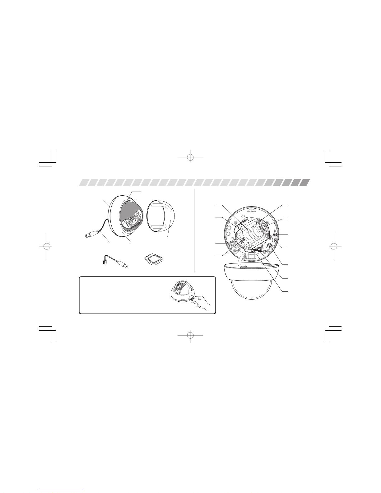
PARTS DESCRIPTION
• Camera body interior
• Exterior
Body cover
Camera body
Inner cover
Dome cover
View angle
adjustment
lever
Focus
adjustment
lever
Lens
Video output
connector for
service monitor
cable
Line phase
adjustment
volume
Video output
terminal for bare
coaxial cable
Camera
Power
input
terminal
• Accessories
Body cover
opener
Cover Removal and Attachment
• To remove the dome cover, pull lightly. To attach it, insert and
press the cover lightly until it snaps together.
• To remove the body cover, insert the opener in the groove between the camera body and the body cover and twist lightly. To
attach it, align the edge of body cover to the groove on the
camera body, and press until it snaps together.
Coaxial video
cable
Coaxial
video cable
Service monitor cable
DIP
switch
DC iris
adjustment
volume
(EG)D3024/563PAL 03.10.8, 0:15 PMPage 3 AdobePageMaker6.5J/PPC
Page 4

EG-4
Creating a Hole in the Ceiling or Wall
Make two holes for the screws affixing the camera body, and one hole for the
power and video cables.
* Use the supplied template to mark the appropriate mounting position on
the ceiling or the wall.
Mounting the Camera Body
Remove the body cover, and mount the
camera body to the ceiling or wall.
Align the housing to the holes you have
made, and use two screws to mount the
camera body.
* Choose screws suitable for the type of ceil-
ing or wall material. Screws with a diameter of 4 to 5 mm is recommended.
INSTALLATION & ADJUSTMENT
2
1 3
• Running cable along
the ceiling or wall
surface
(Back of camera body)
Wall
Press open the perforated
section, and run the cables
through.
Connecting the Cables
Please refer to the diagrams below.
① Connect the video cable from monitor to the equipped video cable.
* When not using the equipped video cable, con-
nect the video cable from monitor to the camera
as shown.
② Connect the power cable.
* When using 12V DC, connect the positive (+) side to the side marked "DC
12V."
• When using 12V DC. • When using 24V AC.
ATTENTION
① Check if the power is off before handling the power cable.
② When using DC power, check for proper polarity before connecting to power sup-
ply. Improper polarity may cause damage to the camera.
(EG)D3024/563PAL 03.10.8, 0:15 PMPage 4 AdobePageMaker6.5J/PPC
Page 5

EG-5
4
Attaching the Service Monitor
When adjusting the camera direction, view angle and focus, use the included
service monitor cable by connecting to the video output connector
• Service monitor is not included.
Adjusting the Camera Direction
Camera body moves in three
ways: Pan,Tilt, and Rotate.
Adjust the direction so that the
lens is aiming at the target.
Adjusting the View Angle, Focus and Iris
Use the lever to adjust the view angle and focus.
The mark
indicates the top
side of camera.
Pan 190°
Tilt 150°
Rotate 210°
Focus adjustment
lever (Lock screw)
View angle adjustment
lever (Lock screw)
5
6
(EG)D3024/563PAL 03.10.8, 0:15 PMPage 5 AdobePageMaker6.5J/PPC
Page 6

EG-6
1 FIX Do not change the switch position from the factory setting.
2
Flickerless
ON Shutter speed to be fixed at 1/120.
(FL)
OFF Normal position
Back Light
ON
Set to this position when a strong light is in the
3
Compensation
back ground.
(BLC)
OFF Normal position
4
Synchronization
INT Internal synchronization mode
Mode
L.L. Line lock mode (24V AC, 50Hz only)
1 FIX Do not change the switch position from the factory setting.
OFF Gain level to be fixed at 4dB.
2
Auto Gain Control
ON
Set to this position to improve camera
(AGC) sensitivity in low light conditions.
Gain level varies from 4dB to 22dB.
Back Light
ON
Set to this position when a strong light is in the
3
Compensation
back ground.
(BLC)
OFF Normal position
4
Synchronization
INT Internal synchronization mode
Mode
L.L. Line lock mode (24V AC, 50Hz only)
Factory Setting
7
DIP Switch Set Up
Set according to lighting conditions.
Attention: DO NOT change “FIX” switch position from the factory setting.
Factory Setting
ZC-D3024CHA/ZC-D3210CHA (Black & White)
ZC-D3024PHA/ZC-D3210PHA (Colour)
(EG)D3024/563PAL 03.10.8, 0:15 PMPage 6 AdobePageMaker6.5J/PPC
Page 7

EG-7
Line Phase Adjustment
(24V AC 50Hz, Line Lock mode)
If necessary, turn the volume to adjust the line phase.
DC Iris Level Adjustment
Set according to lighting conditions.
If necessary, turn the volume to adjust the DC iris level.
Attention: In case of Black & White models, set AGC DIP switch to OFF while
adjusting DC iris level.
Completing the Adjustment and Installation
① Attach the body cover.
8
9
② Attach the dome cover.
10
(EG)D3024/563PAL 03.10.8, 0:15 PMPage 7 AdobePageMaker6.5J/PPC
Page 8

EG-8
SPECIFICATIONS
025-2.0
Tokyo, Japan
www.GANZ.jp
(EG)D3024/563PAL 03.10.8, 0:15 PMPage 8 AdobePageMaker6.5J/PPC
 Loading...