

Page 1

P
P
T
T
1
1
2
2
7
7
N
N
Indoor Vandal Proof 27x PTZ Dome
User Manual
NY: 55 Mall Drive • Commack, NY 11725 (800) 422-6707
CA: 20521 Earl Street • Torrance, CA 90503 (877) 407-9555
www.computarganz.com
Page 2
This lightning flash with arrowhead symbol is intended to alert the user to the
presence of un-insulated "dangerous voltage" within the product's enclosure that
may be of sufficient magnitude to constitute a risk of electric shock to persons.
This exclamation point symbol is intended to alert the user to the presence of
important operating and maintenance (servicing) instructions in the literature
accompanying the appliance.
2/47
Speed Dome Camera Instruction Manual
Page 3
Speed Dome Camera Instruction Manual
3/47
Important Safeguard
1. Read Instructions
Read all of the safety and operating instructions before using the product.
2. Retain Instructions
Save these instructions for future reference.
3. Attachments / Accessories
Do not use attachments or accessories unless recommended by the appliance manufacturer as they may
cause hazards, damage product and void warranty.
4. Water and Moisture
Do not use this product near water or moisture.
Installation
Do not place or moun
installed product may f y
with a mounting devic oper
mounting, follow the manufacturer's instructions and use only mounting accessories recommended by
manufacturer.
Power source
This product should be
5.
t this product in or on an unstable or improperly supported location. Improperly
all, causing serious injury to a child or adult, and damage to the product. Use onl
e recommended by the manufacturer, or sold with the product. To insure pr
6.
operated only from the type of power source indicated on the marking label.
Precautions
Operating
z Before using, make sure power supply and others are properly connected.
z While operating, if any abnormal condition or malfunction is observed, stop using the camera
immediately and then contact your local dealer.
Handling
z Do not disassemble or tamper with parts in he camera.
z Do not drop or subject the camera to shock and vibration as this can damage camera.
z Care must be taken when you clean the clear dome cover. Especially, scratch and dust will ruin your
quality of camera.
Installation and Storage
z Do not install the camera in areas of extreme temperature, which exceed the allowable range.
z Avoid installing in humid or dusty places.
z Avoid installing in places where radiation is present.
z Avoid installing in places where there are strong magnetic fields and electric signals.
z Avoid installing in places where the camera would be subject to strong vibrations.
z Never expose the camera to rain and water.
NOTICENOTICENOTICENOTICENOTICENOTICENOTICENOTICENOTICENOTICENOTICENOTICENOTICENOTICENOTICENOTICENOTICE
side t
Page 4

Speed Dome Camera Instruction Manual
4/47
○
1
Introduction
Fea tu res
5
Product & Accessories
7
Parts Name & Functions
8
○
2
Installation
assembling / AssemblingTerminal Cover Dis
9
DIP Switch Setup
10
Direct Installation on the Ceiling
13
Installation using In-Ceiling Mount Bracket
15
Installation using Ceiling Mount Bracket
16
sing Wall Mount BracketInstallation u
17
Cabling
18
○
3
Operation
Checking Before Operation
20
Preset and Pattern Function Pre-Check
20
Start OSD Menu
21
Reserved Preset
21
Preset
22
Swing
22
Pattern
23
Group
24
Other Motion Functions
25
OSD Display of Main Screen
26
○
4
How to use OSD Menu
General Rules of Menu Operation
27
Main Menu
27
Display Menu for Main Screen
28
Privacy Zone Mask Setup
29
Camera Module Setup
30
Motion Setup
34
Preset Setup
36
Swing Setup
39
Pattern Setup
40
Group Setup
41
System Initialize
43
○5 Specifications
44
Dimension
45
CONTENTS
Page 5

Speed Dome Camera Instruction Manual
5/47
Fe at u re s
Camera Specifications
z CCD Sensor : 1/4" Super HAD color
z Zoom Magnification : × 27 Optical Zoom, × 12 Di
z Day & Night Functi
z Various Focus Mode : Auto-Focus / Manual Focus /
z Independent & Simul
Powerful Pan/Tilt Functions
z Max. 360°/sec high speed Pan/Tilt Motion
z Using Vector Drive Technology, Pan/Tilt motions d in a shortest path. As a result,
time to target view is reduced drama
z For jog operation using a
to locate camera to desired target view. Addition
with zoom-proportional pan/tilt movement.
Preset, Pattern, Swing, Group, Privacy Mask and More…
z MAX. 127 Presets are assignable and characteristics of e ,
such as White Balance, Auto Exposure, La
z Max. 8 set of Swing action can be sto o
preset positions with designated sp
z Max. 4 of Patterns can be rec
trajectory operated by joystick as closely as possible
z Max. 8 set of Group action can be h
combination of Preset or Pattern or Swing
Preset/Pattern/Swings.
z Privacy Masks are assignable, not to intrude on othe
INTR1 ODUCTION
CCD
gital Zoom (Max × 324 Zoom)
on
Semi-Auto Focus.
taneous Camera Characteristic Setup in Preset operation
are accomplishe
tically and the video on the monitor is very natural to watch.
controller, since ultra slow speed 0.05°/sec can be reached, it is very easy
ally it is easy to move camera to a desired position
ach preset can be set up independently
bel, Digital Outputs and so on.
red. This enables to move camera repetitively between tw
eed.
orded and played back. This enables to move camera to follow any
.
stored. This enables to move camera repetitively wit
. A Group is composed of max. 20 entities of
r’s privacy. (8 Privacy Zones)
Page 6

1
INTRODUCTION
/Zoom) Control
z With RS-485 communication, max. 255 of cameras can be controlled at the same time.
o-P protocol can be selected as a control protocol in the current version of firmware.
to display the status of camera and to configure the functions interactively.
d Preset can be displayed on
elays are available.
n be set to move to the corresponding Preset position.
Meanwhile, the output relay can be matched to some specific Preset positions to do counteractions
such as turning on the light or sound the alarm.
z Most camera characteristics can be set up easily and directly with reserved preset, not entering
PTZ(Pan/Tilt
z Pelco-D or Pelc
OSD(On Screen Display) Menu
z OSD menu is provided
z The information such as Camera ID, Pan/Tilt Angle, Alarm I/O an
screen.
Alarm I/O Functions
z 4 alarm sensor Inputs and 2 alarm Output r
z To reject external electric noise and shock perfectly, alarm sensor Input is decoupled with photo
coupler and the relay is used for alarm output.
z The signal range of sensor input is from DC 5.0 to 12.0 volts to adopt various applications.
Meanwhile, the maximum load of relay contact is AC 250V, 3A or DC 28V, 3A.
z If an external sensor is activated, camera ca
Reserved Presets for Special Purpose
into OSD menu. For more information, refer to “Reserved Preset” in this manual.
6/47
Speed Dome Camera Instruction Manual
Page 7
1
INTRODUCTION
Product & Accessories
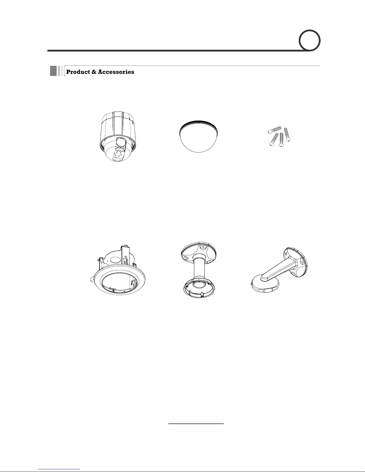
Product & Accessories
z Screws
Options
z Main Body / Terminal Cover z Dome Cover
z Fflush Mount Model(FMK4) z Pendant Mount Model(PMK4) z Wall mount Model(WMK4)
7/47
Speed Dome Camera Instruction Manual
Page 8

INTRODUCTION
1
Parts Name & Functions
Dome Cover
Lockup Scre
w
Drop Prevention
Spring
Terminal Cover
Drop Prevention
Hook
Fuse
Cabling
Terminal Bloc
k
Main Body
Connector
Mounting Hole
z Main Body / Terminal Cover z Terminal Cover
z Dome Cover Do not detach protection vinyl from dome cover before finishing all
installation process to protect dome cover from scratches or dust.
z Terminal Cover This is used to install the camera directly on the ceiling or attach to the
other brackets such as in-ceiling, ceiling and wall mount. After
separating this cover first and then attach this directly to ceiling o to
the other bracket. Camera m st be assembled at the last stage.
z
Drop Prevention Hook
his ro
maintenance. After install the Terminal Cover, please, hang the spring
to the drop prevention hook of main body as shown in picture for
further tasks.
z Lockup Screw After assembling Terminal Cover to main body, screw Terminal Cover
to main body to protect them from separation by vibration and so on.
z Fuse If the fuse is burnt to protect your came from over-current damage, the
fuse have to be replace with new one. The fuse specification is 250V 2A.
However, we recommend consulting with supplier to remove the cause
of over-current.
z Cabling Terminal Block During installation, Power, Video, Communication, Alarm I/O cables are
connected on to this cabling terminal block.
r
u
Drop Prevention Spring
T part keeps the camera from d pping during installation and
8/47
Speed Dome Camera Instruction Manual
Page 9

2
INSTALLATION
Terminal Cover Disassembling
① Remove the Lockup Screw as shown bellow. ② Turn main body on its axis in CCW(Counter-
clockwise) direction and separate it from
Termina l Cove r.
Terminal Cover Assembling
① Check if the su ated
at the arrow mark as shown in the dotted circle.
② Check the 2 m bly before
starting assembly. Line up the mold lines as
and
assemble main body to Terminal Cover. After
mmit of the Plate Spring is loc old line for assem
shown in the dotted circle and turn main body on
its axis in CW(Clockwise) direction
assembling them, screw main body to Terminal
Cover to protect them from separation by
vibration and so on.
9/47
Speed Dome Camera Instruction Manual
Page 10
2
INSTALLATION
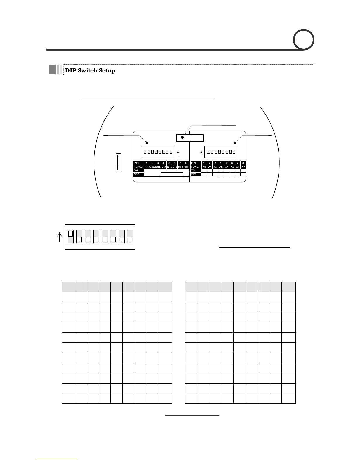
DIP Switch Setup
Be e DIP s
protocol. Do not use the ISP connector. (Authorized person
fore you install the camera, you should set th witches to configure the camera ID, communication
only !)
Communication
Protocol
Camera ID
ON ON
ADDRESS (ID)
OPTIONS
1 2 4 8 16 32 64 128
0000 0000
Refer to
the Manual
N.C
N.O
ISP connector
(for System Upgrade)
(Normal Close)
(Normal Open)
Terminal
Resistor
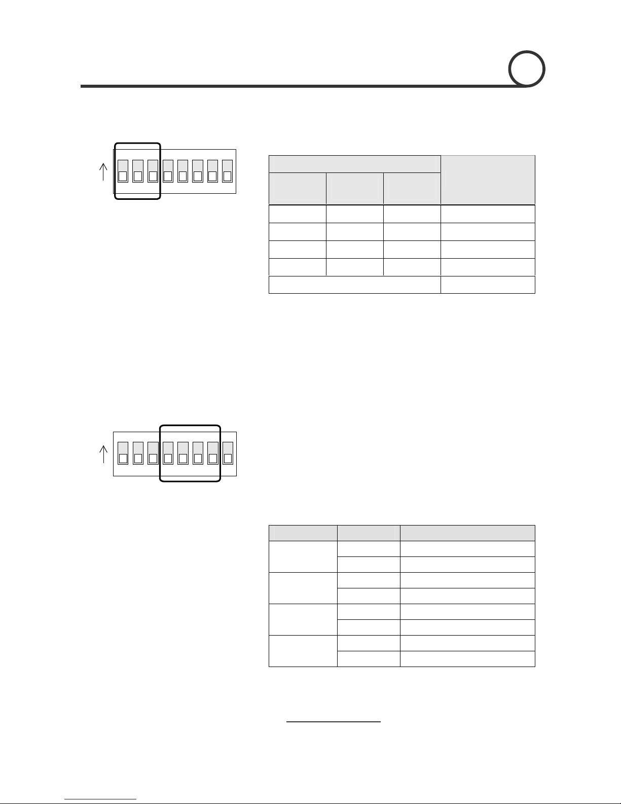
Camera ID Setup
Speed Dome Camera Instruction Manual
10/47
123456
ON
z ID number of camera is set using binary number. The example is
z The range of ID is
ON
shown bellow.
1~255. Do not use 0 as camera ID
. Fact o r y
D is 1.
ol a certain camera, you must match the camera
ing of DVR or Controller.
78
default of Camera I
z If you want to contr
ID with Cam ID sett
1 2 3 4 Pin 1 2 3 4 5 6 7 8 Pin
5 6 7 8
ID 1 2 4 8 16 32 64 128 ID 1 2 4 8 16 32 64 128
1 on off off off off off off off 11 on
on
off on off off off off
2 off on off off off off off off 12 off off on on off off off off
3 on on off off off off off off 13 on
off on on off off off off
4 off off on off off off off off 14 off on on on off off off off
5 on off on off off off off off 15 on
on on
on off off off Off
6 off on on off off off off off 16 off off off off on off off off
7 on on on off off off off off 17 on
off off off on off off off
8 off off off on off off off off 18 off on off off on off off off
9 on off off on off off off off 19 on
on
off Off on off off off
off 20 off10 off on off on off off off on off on off off off
off
Page 11
2
INSTALLATION
Communication Protocol Setup
z Select the appropriate Protocol with DIP switch combination.
ON
Speed Dome Camera Instruction Manual
11/47
123456ON78
Sensor Type Setup
123456
ON
ON
78
Switch State
P0
(Pin 1)
Protocol/Baud rate
P1 P2
(Pin 2) (Pin 3)
OFF OFF OFF PELCO-D, 2400 bps
ON OFF OFF PELCO-D, 9600 bps
OFF ON OFF PELCO-P, 4800 bps
ON ON OFF PELCO-P, 9600 bps
Otherwise Reserved
z If you want to control using DVR or P/T controller, their protocol must
be identical to camera. Otherwise, you can not control the camera.
z If you changed camera protocol by changing DIP S/W, the change
will be effective after you reboot the camera.
z Factory default of protocol is “Pelco-D, 2400 bps”.
z If you want to use Alarm Input, the types of sensor must be selected.
The sensor types are Normal Open and Normal.
state when sensor is
activated.
~ rm l l tp Vo ge hig a wh se s not
va
~ Normal Open Output Voltage is high
No a C ose Ou ut lta is h st te en nsor i
acti ted.
Pin o N Switch State S r eenso Typ
O S r a s pe N enso 1 : Norm l Clo e Ty
ST1 (Pin 4)
OFF S r a e pe enso 1 : Norm l Op n Ty
O S r a s pe N enso 2 : Norm l Clo e Ty
ST2 ( n 5)
OFF Sensor 2 : e
Pi
Normal Open Typ
ON Sensor 3 : Normal Close Type
ST3 ( n 6)
OFF Sensor 3 : e
Pi
Normal Open Typ
ON Sensor 4 : ose e Normal Cl Typ
ST4 ( n 7)
S r a e pe
Pi
OFF enso 4 : Norm l Op n Ty
z If sensor type is not selected properly, the alarm can be activated
v lre erse y.
Page 12
2
INSTALLATION
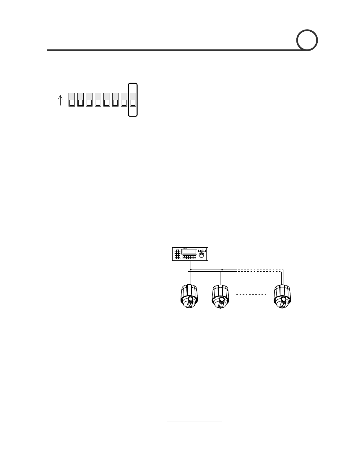
Terminal resistor Setup
123456
ON
ON
78
T
erminal resistor is used if your system is one of following two cases.
z Case ontrol c between camera and co
rela ery lo onne
If communication c very lo elec d
in th minal p his refl gn of
origi nal. Acc gly, the c can b is
case, the terminal resistor of both sides i.e. camera and controller
must be set to ‘ON’ s
z Case2: Multiple cameras are controlled at the same time
f
the terminal resistor
1: C able ntroller is
tively v ng (1:1 c ction)
able is ng, the trical signal will boun
e ter oint. T ected si al cause distortion
nal sig ordin amera e out of control. In th
tate.
Due to similar reasons with case 1, the terminal resisters o
controller and the last camera must be set to ‘ON’ state. Last camera
means decided by cable length. Do not turn on
of all cameras.
Controller
#1
Terminal Resistor ON
RS-485
#2 #n
Terminal Resis
OFF
st Terminal Resistotor Terminal Resi or
r
OFF ON
12/47
Speed Dome Camera Instruction Manual
Page 13
2
INSTALLATION
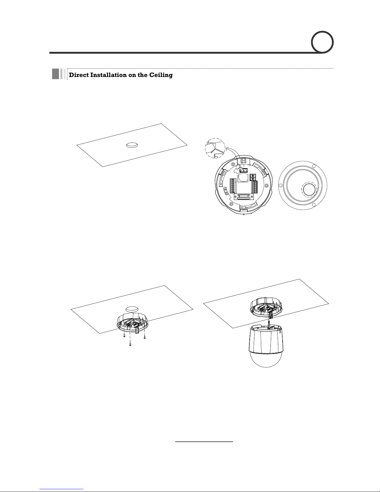
Direct Installation on the Ceiling
① To pass cables to upside of ceiling
about 50~60mm hole on the ceiling panel.
② For cable connection, remove the pre-defined
hole mark on the Rubber Gasket and locate the
cle.
, please, make
summit of the Plate Spring at the arrow mark as
shown in the dotted cir
Rubber Gasket
③ After assembling the Rubber Gasket to the
Terminal Cover, install Terminal Cover on ceiling
tex and connect cables to terminal blocks.
④ Connect the “Drop Prevention Spring” to the main
body to prevent camera from drop.
13/47
Speed Dome Camera Instruction Manual
Page 14

2
INSTALLATION
before
starting assembly. Line up the mold lines as
and
assemble main body to Terminal Cover.
⑤ Check the 2 mold line for assembly
⑥ Tighten the Lockup Screw as shown bellow.
shown in the dotted circle and turn main body on
its axis in CW(Clock-Wise) direction
14/47
Speed Dome Camera Instruction Manual
Page 15
2
INSTALLATION
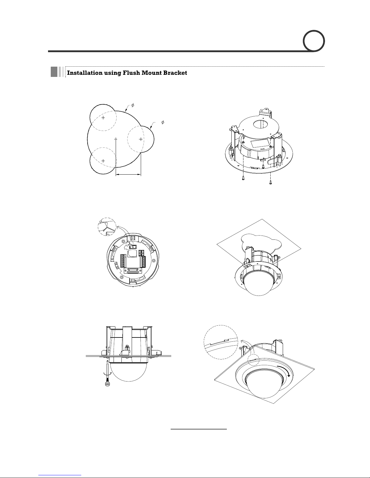
Installation using Flush Mount Bracket
Cut the panel of ceiling as shown bellow.
Speed Dome Camera Instruction Manual
15/47
①
170
80
② Assemble Terminal C er of camera to the In-
Ceiling Mount Bracket as shown bellow.
ov
3-
75
Hole Dimension(mm)
③ Locate the summit of the plate spring at the arrow
mark as shown in the dotted circle.
④ Assemble main body to Terminal Cover and
insert the assembly into ceiling tex.
⑤ Screw camera to ceiling tex with 3 screws tightly.
⑥ Assemble Deco. Ring with camera and turn Deco.
Ring on its axis in CW(Clockwise) direction.
Page 16

2
INSTALLATION
Installation using Pendant Mount Bracket
① To pass cables to upside of ceiling, please ② Assemble Terminal Cover to Ceiling Mount
racket with 3 screws. (
make
about 50~60mm hole on the ceiling panel and
attach the Ceiling mount bracket on it.
B Rubber Do not use
Gasket !)
Locate the summit of the Plate Spring at the arrow
mark. (For more information, refer to the “Terminal
Cover Assembling” section)
③ Connect “Drop Prevention Spring” to main body
to prevent camera from drop. Line up the mold
lines and turn main body on its axis in
CW(Clockwise) direction and assemble main
body to Terminal Cover.
④ After assembling them, screw main body to
Terminal Cover to protect them from separation
by vibration and so on.
16/47
Speed Dome Camera Instruction Manual
Page 17

2
INSTALLATION
Installation using Wall Mount Bracket
① Install Wall Mount Bracket on wall. ② Assemble Terminal Cover to Wall Mount Bracket
with 3 screws. (Do not use Rubber Gasket !
)
Locate the summit of the Plate Spring at the arrow
mark. (For more information, refer to the “Terminal
Cover Assembling” section)
③ Connect “Drop Prevention Spring” to main body
to prevent camera from drop. Line up the mold
④ After assembling them, screw main body to
Terminal Cover to protect them from separation
by vibration and so on. lines and turn main body on its axis in
CW(Clockwise) direction and assemble main
body to Terminal Cover.
17/47
Speed Dome Camera Instruction Manual
Page 18

2
INSTALLATION
Cabling
Light
Alarm
Buzzer
Sensor
Output Devices
Moinitor
Controller
/ DVR
RS-485
BNC
Power
IrDA
Sensor
Door
Switch
PWR(+)
PWR(-)
VIDEO(+)
VIDEO(-)
RS-485(+)
RS-485(-)
RELAY2
Speed Dome Camera Instruction Manual
18/47
RELAY1
IN COM+
IN1
IN2
IN3
IN4
Terminal Cover
Power Connection
z Please, check the voltage and current capacity of rated power carefully. Rated power is indicated in the
back of main unit.
Rated Power Input Voltage Range Current Consumption
AC 24V AC 17V ~ 29V 0.6 A
eo Connection Vid
z Connect with BNC coaxial cable.
RS-485 Communication
z For PTZ control, connect this line to keyboard and DVR. To control multiple cameras at the same time,
RS-485 communication lines of them is connected in parallel as shown below.
Keyboard Controller / DVR
RS-485
+
-
#1
+
-
#2
+
-
#n
+
-
Page 19

2 INSTALLATION
Alarm I/O Connection
z Sensor Input
Before connecting sensors, check driving voltage and output signal type of the sensor. Since output
gnal types of the sensors are divided into Open Collector and Voltage Output type in general, the
be done properly after considering these typed. Also, the sensor type, i.e. “Normal Open”
IN COM+
Internal
+5V~12V
IN 1-
IN 4-
Sensor 1 Output
+
+
-
-
+
-
Sensor 4 Output
si
cabling must
or “Normal Close” in Dip switch in main body of camera must be set properly.
Signal Description
IN COM+ Connect (+) c power source fo ors to this port as
shown in the circuit above.
able of electric r Sens
IN1−, IN 2 −, I N 3 −, I n 4 − Connect output of sensors for each port as shown in the circuit above.
z Relay Output
OUT 1
AC or DC
Speed Dome Camera Instruction Manual
19/47
OUT 2
AC or DC
Internal
LOAD
LOAD
Maximum allowable electrical load of relay is shown bellow table.
Drive Power DC Power AC 110V Power AC220V Power
Max. Load DC 28V, 3A AC110V, 3A C250V, 3A A
Page 20

Speed Dome Camera Instruction Manual
20/47
Page 21

Check points before operation
z Before power is applied, please check the cables carefully.
z The camera ID of the controller must be identical to that of the target camera. The camera ID can be checked
by reading DIP switch of the camera.
z If your controller supports multi-protocols, the protocol must be changed to match to that of the camera.
z If you changed camera protocol by changing DIP switch, the change will be effective after you reboot the
camera.
z Since the operation method can be different for each controller available, refer to the manual for your
controller if camera can not be controlled properly. The operation of this manual is based on the standard
Pelco® Controller.
Preset and Pattern Function Pre-Check
z Check how to operate preset and pattern function with controller or DVR in advance to operate camera
function fully when using controller or DVR.
z Refer to the following table when using standard Pelco® protocol controller.
< Go Preset > Input [Preset Number] and press [Preset] button shortly.
< Set Preset > Input [Preset Number] and press [Preset] button for more than 2 seconds.
< Run Pattern > Input [Pattern Number] and press [Pattern] button shortly.
< Set Pattern > Input [Pattern Number] and press [Pattern] button for more than 2 seconds.
z If controller or DVR has no pattern button or function, use shortcut keys with preset numbers. For more
information, refer to “Reserved Preset” in this manual.
OPERATION 3
21/47
Speed Dome Camera Instruction Manual
Page 22

3
OPERATION
Starting OSD Menu
Swing, Group and Alarm I/O function can be z Function Using the OSD menu, Preset, Pattern,
configured for each application.
z Enter Menu <Go Preset> [95]
Reserved Preset
<Go Preset> [95] : Enters into OSD menu
<Go Preset> [131~134]
z Description Some Preset numbers are reserved to special functions.
z Function
: Runs Patte Function 1 ~ 4 rn
<Go Preset> [141~148] : Runs Swing Function 1 ~
<Go Preset> [151~158]
: Runs Group Function 1 ~ 8
<Go Preset> [161~162] : Sets Relay Output 1 ~ 2 to OFF
<Set Preset> [161~162] : Sets Relay Output 1 ~ 2 to ON
to ON
<Se FF
<Go Pr
<Go Pr
<Go Pr
<Go Preset> [173] : Sets Camera Flickerless Mode to ON
era Focus Mode to Manual
<Go Preset> [176] : Sets Camera Focus Mode to SEMI-AUTO
<Go Preset> [177] : Sets Day & Night Mode to AUTO
<Go Preset> [178] : Sets Day & Night Mode to NIGHT
<Go Preset> [179] : Sets Day & Night Mode to DAY
<Go Preset> [180] : Sets Line-Lock Mode to OFF
<Go Preset> [181] : Sets Line-Lock Mode to ON
<Go Preset> [190] : Sets OSD Display Mode to AUTO (Except Privacy Mask)
<Go Preset> [191] : Sets OSD Display Mode to OFF (Except Privacy Mask)
<Go Preset> [192] : Setting OSD Display Mode to ON (Except Privacy Mask)
<Go Preset> [193] : Sets all Privacy Mask Display to OFF
<Go Preset> [194] : Sets all Privacy Mask Display to ON
<Go Preset> [167] : Set Zoom Proportional Function
t Preset> [167] : Set Zoom Proportional Function to O
eset> [170] : Sets Camera BLC or WDR Mode to OFF
eset> [171] : Sets Camera BLC or WDR Mode to ON
eset> [172] : Sets Camera Flickerless Mode to OFF
<Go Preset> [174] : Sets Camera Focus Mode to AUTO
<Go Preset> [175] : Sets Cam
22/47
Speed Dome Camera Instruction Manual
Page 23

3
OPERATION
Preset
z Function M
fr starting OSD menu.
Camer ics (i.e. White Balance, Auto Exposure) can be set up independently
for each preset. Label should be blank and Relay Outputs should be set to OFF as default.
All characteristics can be set up in OSD menu.
Preset> [1~128]
z Run Preset <Go Preset> [1~128]
eset To
ax. 127 positions can be stored as Preset position. The Preset number can be assigned
om 1 to 128, but 95 is reserved for
a characterist
z Set Preset
<Set
z Delete Pr delete Preset, use OSD menu.
Swing
Function By ve between 2 Preset positions
re u m the preset assigned as the 1st
point to direction. Then camera
mo et assig d as the 1st point in
C se) d
In t assi preset assigned as the 2nd
p n its ns on its
ax oun
Sp rom 1°
Set Swing
To men
Run Swing
Method 1) <Run P n> [Swing NO
Method 2) <Go Pr
Swing 3 : <Run Pattern> [13]
Swing 3 : <Go Preset> [143]
Delete Swing To me
z using Swing function, you can make camera to mo
peatedly. When swing f nction runs, camera moves fro
the preset assigne
ves from the pres
d as the 2nd point in CW(Clockwise)
ned as the 2nd point to the preset assigne
CW(Counterclockwi irection.
Speed Dome Camera Instruction Manual
23/47
1st Preset
case that the prese gned as the 1st point is same as the
oint, camera turns o axis by 360° in CW(Clockwise) direction and then it tur
is by 360° in CCW(C terclockwise) direction.
eed can be set up f /sec to 180°/sec.
z set Swing, use OSD u.
z atter .+10] ex) Run
eset> [Swing NO.+140] ex) Run
z delete Swing, use OSD nu.
2nd Preset
C
W
D
i
r
e
1
c
t
i
on
2
C
C
W
D
i
r
ec
t
i
on
Page 24

3
OPERATION
Pattern
z Function Pattern Function is that a camera memorizes the path (mostly curve path) by joystick of
controller for assigned time and revives the path exactly as it memorized.
z Set Pattern
Pattern can be created by one of following two methods.
Method 1) <Set Pattern> [Pattern NO.]
ing screen is displayed as bellow.
4 Patterns are available and Maximum 1200 communication commands can be stored in
a pattern.
{ Pattern edit
EDIT PATTERN 1
[NEAR:SAVE /FAR:DELETE]
0/0/x1/N
{ Movement by Joystick and preset movement can be memorized in a pattern.
{ The rest memory size is displayed in progress bar.
{ To save the recording, press NEAR key and to cancel, press FAR key.
Method 2) OSD Using OSD Menu: See the section “How to use OSD Menu”.
z Run Pattern
z Delete Pattern
Method 1) <Run Pattern> [Pattern NO.]
Method 2) <Go Preset> [Pattern NO.+130]
ex) Run Pattern 2 : <Run Pattern> [2]
ex) Run Pattern 2: <Go Preset> [132]
Use OSD menu to delete a Pattern.
24/47
Speed Dome Camera Instruction Manual
Page 25

3 OPERATION
Group
z Function The group function allows running sequence of Presets, Pattern and/or Swings. Max 8
group can be stored. Each group can have max 20 action entities which can be preset,
up in Group setup. Dwell time between actions can be set up also.
pattern or swing. Preset speed can be set up and the repeat number of Pattern & Swing
can be set
Speed Dome Camera Instruction Manual
25/47
Preset 1 Pattern 1 Swing 1
Dwell Time
Max 20 Entities
z Set Group Use OSD Menu to create a Group.
z Run Group Method 1) <Run Pattern> [Group NO.+20]
Method 2) <Go Preset> [Group NO.++150]
ex) Run Group 7 : <Run Pattern> [27]
ex) Run Group 7 : <Go Preset> [157]
z Delete Group Use OSD Menu to delete.
Page 26

3
OPERATION
Other Functions
z Power Up Action
z Auto Flip In case that tilt angle arrives at the top of tilt orbit(90°), zoom module camera turns on
its axis by 180° at the top of tilt orbit and moves to opposite tilt direction (180°) to keep
tracing targets. If this function is set to OFF, tilt movement range is 0 ~ 95°.
z Parking Action This function enables to locate the camera to specific position automatically if operator
doesn’t operate the controller for a while. The Park Time can be defined as a interval
from 1 minute to 4 hours.
z Alarm I/O 4 Alarm Input and 2 Alarm output (Relay output) are used. If an ext rnal sensor is
ve to corresponding preset position. Also, the output
relay can be matched to some specific preset positions to do counteractions such as
m ut is
ask Privacy Masks can be created on the arbitrary position to
hide objects such as windows, shops or private house. With Spherical Coordinates
system, powerful Privacy Zone Mask function is possible.
z GLOBAL/LOCAL
Image Setup
WB(White Balance) and AE(Auto Exposure) can be set up independently for each
preset. There are 2 modes, "Global" mode & "Local" mode. The Global mode means that
WB or AE can be set up totally and simultaneously for all presets in "ZOOM CAMERA
SETUP" menu. The Local mode means that WB or AE can be set up independently or
separately for each preset in each preset setup menu. Each Local WB/AE value should
activate correspondingly when camera arrives at each preset location.
During jog operation, Global WB/AE value should be applied. All Local WB/AE value
do not change although Global WB/AE value changes.
z SemiAuto Focus
This mode exchanges focus mode automatically between Manual Focus mode and Auto
Focus mode by operation. Manual Focus mode activates in preset operation and Auto
Focus mode activates during jog operation. With Manual mode at presets, Focus data is
memorized in each preset in advance and camera calls focus data in correspondence
with presets as soon as camera arrives at a preset. It should shorten time to get focuses.
Focus mode changes to Auto Focus mode automatically when jog operation starts.
This function enables to resume the last action executed before power down. Most of
actions such as Preset, Pattern, Swing and Group are available for this function but Jog
actions are not available to resume.
e
activated, camera can be set to mo
turning on the light or sounding the alar . It is noted that the latest alarm inp
effective if multiple sensors are activated.
z Privacy Zone M To protect privacy, MAX. 8
26/47
Speed Dome Camera Instruction Manual
Page 27

3
OPERATION
OSD Display of Main Screen
Camera ID
A
larm Information
Action Title
Preset Label
LABEL12345 PRESET1
I:1--- O:-2
CAM 1
P/T/Z Information
15/4/x1/N
Current Pan/Tilt angle in degree, zoom magnification and a compass direction.
z P/T/Z Information
z Camera ID Current Camera ID(Address).
z Action Title
z Preset Label
on
Followings are possible Action Titles and their meaning.
"SET PRESET ×××" When Preset ××× is stored
"PRESET ×××" When camera reach to Preset ×××
"PATTERN ×" When Pattern × is in action
"SWG×/PRESET ×××" When Swing × is in action
"UNDEFINED" When undefined function is called to run
The Label stored for specific Preset.
z Alarm Informati This information shows current state of Alarm I/O. The character ‘O’ of first line stands
for Output and ‘I’ of second line means Input. If an I/O point is ON state it will show a
number corresponding to each point. If an I/O point is OFF state, '-' will be displayed.
Ex) Point 2 & 3 of inputs are ON and Point 1 of outputs is ON, OSD will show as below
I:-23- O:1-
27/47
Speed Dome Camera Instruction Manual
Page 28

Speed Dome Camera Instruction Manual
28/47
General Rules of Key Operation for Menu
z The menu items surrounded with ( ) always has its sub menu.
z For all menu level, to go into sub menu, press NEAR key.
z To go to up-one-level menu, press FAR key.
z To move from items to item in the menu, use joystick in the Up/Down or Left/Right.
z To change a value of an item, use Up/Down of the joystick in the controller.
z Press NEAR key to save values and Press FA R key to cancel values.
z Specifications and functions should be different by models.
Main Menu
SPEED DOME CAMERA
-----------------------FORMAT
<DISPLAY SETUP>
<DOME CAMERA SETUP>
<SYSTEM INITIALIZE>
EXIT
<SYSTEM IN ION>
z System Information Displays system information and configuration.
z Display Setup Enable/Disable of OSD display on Main
Screen.
Dome Caz mera Setup
Configure various functions of this camera.
z System In guration and sets all
uration.
HOW TO USE
itialize Initializes system confi
data to factory default config
4
OSD MENU
Page 29

4
HOW TO USE OSD MENU
Display Setup
Speed Dome Camera Instruction Manual
29/47
DISPLAY SETUP
------------------------
CAMERA ID ON
PTZ INFORMATION AUTO
ACTION TITLE AUTO
PRESET LABEL AUTO
ALARM I/O AUTO
<SET NORTH DIRECTION>
<PRIVACY ZONE>
BACK
EXIT
This menu defines Enable/Disable of OSD display on Main Screen. If an
O, the item is displayed only when the value of it is
.
O]
[ON/OFF/AUTO]
z Preset Label [ON/OFF/AUTO]
z Alarm I/O [ON/OFF/AUTO]
item is set to be AUT
changed
z Camera ID [ON/OFF]
z PTZ Information [ON/OFF/AUT
z Action Title
Compass Direction Setup
SET NORTH DIRECTION
------------------------
MOVE TO TARGET POSITION
[NEAR:SAVE /FAR:CANCEL
Set North to assign compass direction as criteria. Move camera and
press NEAR button to save.
Page 30

4
HOW TO USE OSD MENU
PRIVACY ZONE MASK Setup
PRIVACY ZONE
------------------------
MASK NO 1
UNDEFINED
DISPLAY OFF
CLEAR MASK CANCEL
<EDIT MASK>
BACK
EXIT
Select area in image to mask.
z Mask No [1~8]
Select ber. If the selected mask has
read moves as it was set.
Mask num
al y data, camera
Otherwise, “UNDEFINED” will be displayed
under
[ON/O
Sets if camera makes mask shows or not on
image
z Clear Mask [CANCEL/OK]
Deletes data in the selected mask NO.
“Mask NO”.
z Display FF]
s.
Privacy Zone Area Setup
EDIT MASK 1
------------------------
MOVE TO TARGET POSITION
[NEAR:SELECT/FAR:CANCEL]
Move camera to area to mask. Then the menu to adjust mask size will be
displayed.
Privacy Zone Size Adjustment
EDIT MASK 1
------------------------
[ :ADJUST MASK WIDTH]
[ :ADJUST MASK HEIGHT]
[NEAR:SAVE /FAR:CANCEL]
Adjust mask size. Use joystick or arrow buttons to adjust mask size.
z (Left/Right) Adjusts mask width.
z (Up/Down) Adjusts mask height.
30/47
Speed Dome Camera Instruction Manual
Page 31

4
HOW TO USE OSD MENU
Speed Dome Camera Instruction Manual
31/47
CAMERA SETUP
ZOOM CAMERA SETUP
------------------------
FOCUS MODE SEMIAUTO
DIGITAL ZOOM ON
LINE LOCK OFF
IMAGE FLIP OFF
SHARPNESS 16
STABILIZATION OFF
<WHITE BALANCE SETUP>
<AUTO EXPOSURE SETUP>
BACK
EXIT
Setup the general functions of zoom camera module.
z Focus Mode [AUTO/MANUAL/SEMIAUTO]
mera focus mode. Sets ca
{ SEMIAUTO Mode
This mode exchanges focus mode automatica
between Manual Focus mo
lly
de and Auto Focus mode.
Manual Focus mode activates in preset operation
cus mode activates when jog operation
ual mode at presets, Focus data is
memorized in each preset in advance and camera
in correspondence with presets as
z Digital Zoom
and Auto Fo
starts.
With Man
calls focus data
soon as camera arrives at a preset.
[ON/OFF]
Sets digital zoom function to ON/OFF. If this is set to
OFF, optical zoom function runs but zoom function
[ON/OFF]
If Line lock sync is ON, video signal is synchronized
with AC power.
z Image Flip [ON/OFF]
Flip the Image.
z Sharpness [0~32]
Sets image sharpness.
z Stabilization [ON/OFF]
s.
wer resolution when this
function is turned on because it use the digital zoom
nctio ay not work properly in
the following conditions.
Dark scene or Low contrast scene
High frequency vibration
During Pan/Tilt/Zoom/Focus moving
During Iris/Shutter/Gain moving
stops at the end of optical zoom magnification.
z Line Lock
Compensates image vibration by wind or other
The image resolution with this function should be
lo than normal image
fu n. Also this function m
Page 32

4
HOW TO USE OSD MENU
White Balance Setup
WB SETUP - GLOBAL
------------------------
WB MODE AUTO
RED ADJUST -- BLUE ADJUST ---
BACK
EXIT
z WB Mode [AUTO/MANUAL]
In Manual mode, Red and Blue level can be set
z Red Adjust
z Blue Adjust
up manually
[0~255]
[0~255]
Auto Exposure Setup
AE SETUP - GLOBAL
------------------------
BACKLIGHT OFF
DAY/NIGHT AUTO
BRIGHTNESS 50
IRIS AUTO
SHUTTER ESC
AGC MIDDLE
SSNR MIDDLE
SENS-UP <AUTO>
BACK
EXIT
z Backlight
(or WDR)
ure may appear
as a silhouette. Backlight compensation
enhances objects in the center of the picture. The
ill
e iris so that the object in the sensitive
area is properly exposed.
has WDR(Wide Dynamic Range)
function, which are better function than BLC.
Light Compensation) function removes
in a limited environment such as
parking garage.
z Day/Night
z IRIS
is should have highest
r Speed should
xed and Iris
has lower priority in adjusting AE, in comparison
[OFF/WDR/BLC/HLC] or [OFF/BLC/HLC]
Sets Backlight Compensation. If a bright backlight
is present, the subjects in the pict
dark or
camera uses the center of the picture to adjust the
iris. If there is a bright light source outside of this
area, it will wash out to white. The camera w
adjust th
Some modles
HLC(High
the high light
[AUTO/DAY/NIGHT]
z Brightness [0~100]
Adjusts brightness of images. Iris, Shutter Speed
and Gain are adjusted automatically in
correspondence with this value.
[AUTO/MANUAL(F1.6~F28)]
If Iris is set to Auto, Ir
priority in adjusting AE and Shutte
be fixed.
If Iris is set to Manual, Iris should be fi
w
ith others.
32/47
Speed Dome Camera Instruction Manual
Page 33

4
HOW TO USE OSD MENU
WDR (Wide Dynamic Range) Setup
z Shutter Speed [ESC/A.Flicker/Manual(×256~1/120000 sec)]
If Iris is set to Manual and Shutter Speed is set to
ESC, Shutter Speed should have highest priority. If
Shu to A.Flicker, to remove
Flick
for NTSC or PAL.
[OFF/LO MANUAL(5~41dB)]
Enhances image brightness automatically in case
that luminance level of image signal is too low.
z [OFF/LOW/MIDDLE/HIGH]
Enhances images by deducting noises when gain
level of images is too high.
tter Speed is set
er, Shutter Speed should be set to 1/100 sec.
and 1/120 f
z AGC W/MIDDLE/HIGH/
SSNR
z SENS-UP [AUTO(2~256)/OFF]
Activates Slow Shutter function when luminance of
image (signal) is too dark.
It is possible to set up the maximum number of
frames piled up one on another by Slow Shutter
function.
WDR
------------------------
LIMIT MIDDLE
LEVEL 50
BACK
EXIT
z Limit
z Level
[LOW/MIDDLE/HIGH]
[0~100]
33/47
Speed Dome Camera Instruction Manual
Page 34

4
HOW TO USE OSD MENU
HLC (High Light Compensation) Setup
HLC
------------------------
LIMIT LOW
COLOR 5
BACK
EXIT
z Limit
le, when there is a car
z Level [0~10]
to block light sources
[AUTO/MANUAL]
When there are too bright lights, this function
blocks light sources on the images to have
better images. For examp
coming to a camera at night, this function
bocks car headlights to recognize its number
plate.
Assigns colors of masks
34/47
Speed Dome Camera Instruction Manual
Page 35

4 HOW TO USE OSD MENU
Motion Setup
Setup the general functions ons.
z Motion Lock
up and delete those functions, enter into
OSD menu.
z Power Up Action
Refer to “Other Functions" section.
z Auto Flip [ON/OFF]
Refer to “Other Functions" section.
z Jog Max Speed [1°/sec ~360°/sec]
Sets maximum jog speed. Jog speed is
inversely proportional to zoom magnification.
As zoom magnification goes up, pan/tilt speed
goes down.
z Jog Direction [INVERSE/NORMAL]
If you set this to ‘Inverse’, the view in the screen
is moving same direction with jog tilting. If
‘Normal’ is selected, the view in the screen is
moving reversely.
z Freeze in Preset [ON/OFF]
At start point of preset movement, camera
starts freezing the image of start point. Camera
keeps displaying the image of start point
during preset movement and does not display
the images which camera gets during preset
movement. As soon as camera stops at preset
end point, camera starts displaying live images
which it gets at preset end point.
This function availability should be different by
models.
of Pan/Tilt moti
MOTION SETUP
------------------------
MOTION LOCK OFF
PWR UP ACTION ON
AUTO FLIP ON
JOG MAX SPEED 120/SEC
JOG DIRECTION INVERSE
FRZ IN PRESET OFF
<PARKING ACTION SETUP>
<ALARM INPUT SETUP>
BACK
EXIT
[ON/OFF]
If Motion Lock is set to ON, it is impossible to
set up and delete Preset, Swing, Pattern and
Group. It is possible only to run those functions.
To set
[ON/OFF]
35/47
Speed Dome Camera Instruction Manual
Page 36

4
HOW TO USE OSD MENU
Parking Action Setup
PARKING ACTION SETUP
------------------------
PARK ENABLE OFF
WAIT TIME 00:10:00
PARK ACTION HOME
BACK
EXIT
If Park Enable is set to ON, camera runs assigned function automatically
comma ssigned "Wait Time".
z Park Enable [O
z Wait Time [1
A
th mand from controller for this time
pe
z Park Action [H OUP/PREV
ACTION]
Sets what a camera should do when there is no
command pre-defined
tim ME”). If Park Action is set to
“HOME”
wh
Pa
ru
re
if there is no PTZ nd during a
N/OFF]
~59 sec/1~180 minute]
camera automatically run a "Part Action" if
ere is no com
riod.
OME/PRESET/PATTERN/SWING/GR
from a controller for the
e period (“WAIT TI
, the camera moves to the home position
ich is memorized when the system boots. If
rk Action is set to “PREV. ACTION”, the camera
ns the previous action which it ran most
cently.
Alarm Input Setup
Speed Dome Camera Instruction Manual
36/47
z Alarm No [1
Se
z Action [NOT USED/PRESET/PATTERN/SWING/GROUP]
Sets actions to run when sensor is input.
z Hold Time [E
Sets the time
by
per
Action
action b
is set to n” does not
ac
z Po Action [HOME/PRESET/PATTERN/SWING/GROUP/PREV
ACTION]
Sets the action that a camera should run after the
time period in“HOLD TIME” passes
~4]
lects a sensor number to set up.
ALARM INPUT SETUP
------------------------
ALARM NO. 1
ACTION NOT USED
HOLD TIME ENDLESS
POST ACTION HOME
BACK
EXIT
NDLESS/1~59 sec/1~180 minute]
period for the action which is run
external sensor activation. After the time
iod passes, the action pre-defined in “Post
” runs sequentially in succession to the
y external sensor activation. If this option
“ENDLESS”, “Post Actio
tivate.
st
Page 37

4
HOW TO USE OSD MENU
PRESET Setup
PRESET SETUP
------------------------
PRESET NO. 1
CLR PRESET CANCEL
<EDIT SCENE>
<EDIT LABEL> LABEL123
<RELAY OUT> 1 CAM ADJUST GLOBAL
BACK
EXIT
z Preset Number [1~128]
If a selected preset is already defined, camera
e-defined position and preset
characteristics such as Label and Relay Outputs
elected preset is not
z Clear Preset
rent Preset data
moves to pr
show on monitor. If a s
defined, “UNDEFINED” shows on monitor.
[CANCEL/OK]
Delete cur
z Edit Preset Scene Redefine current Preset scene position (i.e. PTZ).
z Edit Preset Label
z Edit Relay Out
z CAM Adjust
WB(White Balance) and AE(Auto Exposure) can
be set up independently for each preset. There
are 2 modes, "Global" mode & "Local" mode. The
l mode means that WB or AE can be set up
presets in
"ZOOM CAMERA SETUP" menu.
h preset
in each preset setup menu. Each Local WB/AE
ingly when
Edits Label to show on monitor when preset runs.
MAX. 10 alphabets are allowed.
Define Relay output. If an Output point is ON
state it will show a number corresponding to
each point. Otherwise, '-' will be displayed.
[GLOBAL/LOCAL]
Globa
totally and simultaneously for all
The Local mode means that WB or AE can be set
up independently or separately for eac
value should activate correspond
camera arrives at each preset location. During
jog operation, Global WB/AE value should be
applied.
All Local WB/AE value should not change
although Global WB/AE value changes. If “Local’’
is selected, Menu to set WB/AE shows on
monitor.
37/47
Speed Dome Camera Instruction Manual
Page 38

4
HOW TO USE OSD MENU
Edit Preset Scene
EDIT SCENE - PRESET 1
------------------------
MOVE TO TARGET POSITION
[NEAR:SAVE /FAR:CANCEL]
○1 Using Joystick, move camera to desired position.
○
2
By pressing NEAR k
○
3
Press FA R key to ca
ey, save current PTZ data.
ncel.
Edit Preset Label
EDIT LABEL - PRESET 1
------------------------
[ ]
----------
1234567890 OK
ABCDEFGHIJ CANCEL
KLMNOPQRST
UVWXYZabcd
efghijklmn
opqrstuvwx
yz<>-/:.
----------
① Edits label to sho
Edit Label menu or. As soon as
cting
② Using Left/Right/Up/Do
character from the
the NEAR key.
If you want to use blank, choose Space character (" "). If you want to
delete a character
③ If you complete t
NEAR key to save d label. To abort current change, move
cursor to "Cancel" and press NEAR key.
w on monitor when camera arrives at presets. In
, a reverse rectangular is curs
finishing sele alphabet, cursor moves to the next digit.
Speed Dome Camera Instruction Manual
38/47
wn of joystick, move to an appropriate
Character set. To choose that character, press
before, use back space character (" ←").
he Label editing, move cursor to "OK" and press
complete
Current Cursor Position
[ ]
---------1234567890
ABCDEFGHIJ
Back Space Char.Space Char.
KLMNOPQRST
UVWXYZabcd
efghijklmn
opqrstuvwx
yz<>-/:.
----------
Page 39

4
HOW TO USE OSD MENU
Relay Out Setup
RELAY OUT - PRESET 1
------------------------
RELAY OUT 1 OFF
RELAY OUT 2 OFF
BACK
EXIT
z Relay Out × [ON/OFF]
ed preset. Sets Relay Outputs for assign
39/47
Speed Dome Camera Instruction Manual
Page 40

Speed Dome Camera Instruction Manual
40/47
4
HOW TO USE OSD MENU
Swing Setup
SWING SETUP
------------------------
SWING NO. 1
1ST POS. NOT USED
2ND POS. NOT USED
SWING SPEED 30/SEC
CLEAR SWING CANCEL
BACK
EXIT
z Swing Number [1
Se Swing
has not defined, "NOT USED" is displayed in 1st
Position and 2nd Position
z 1st Position
2nd Position
[PRESET 1~128]
Set up the 2 position for Swing function. If a
selected preset is not defined, "UNDEFINED" will
be displayed as shown below.
When swing function runs, camera moves from the
preset assigned as the 1st point to the preset
assigned as the 2nd point in CW(Clockwise)
direction. Then camera moves from the preset
assigned as the 2nd point to the preset assigned as
the 1st point in CCW(Counterclockwise) direction.
In case that the preset assigned as the 1st point is
same as the preset assigned as the 2nd point,
camera turns on its axis by 360° in CW direction
and then it turns on its axis by 360° in CCW
direction.
z Swing Speed [1°/sec ~180°/sec]
Sets Swing speed from 1°/sec to 180°/sec.
z Clear Swing [CANCEL/OK]
Deletes current Swing data.
~8]
lects Swing number to edit. If a selected
SWING SETUP
----------------------- SWING NO. 1
1ST POS. PRESET5
2ND POS. NOT USED
UNDEFINED
40/47
Speed Dome Camera Instruction Manual
Page 41

4
HOW TO USE OSD MENU
Pattern Setup
PATTERN SETUP
------------------------
PATTERN NO. 1
UNDEFINED
CLR PATTERN CANCEL
<EDIT PATTERN>
BACK
EXIT
z Pattern Number ~4 ]
be displayed under
n number.
z Edit Pattern Starts editing pattern.
[1
Selects Pattern number to edit.
If a selected pattern number is not defined,
"UNDEFINED" will
selected patter
z Clear Pattern [CANCEL/OK]
Deletes data in current pattern
Edit Pattern
EDIT PATTERN 1
------------------------
MOVE TO START POSITION
[NEAR:START /FAR:CANCEL]
① By using Joystick, move to start position with appropriate zoom. To
start pattern re
FAR key.
② Move camera w
memorize the p urve path) in a selected pattern. The
y s mory size is displayed in the
form of bar. Maximum 1200 communication commands can be
stored in a patte
③ To save data an ancel recording and
delete record data, press FAR key.
cording, press NEAR key. To exit this menu, press
ith joystick of controller or run preset function to
ath (mostly c
EDIT PATTERN 1
[NEAR:SAVE /FAR:DELETE]
0/0/x1/N
total memor ize and the rest me
rn.
d exit, press NEAR key. To c
41/47
Speed Dome Camera Instruction Manual
Page 42

4
HOW TO USE OSD MENU
Speed Dome Camera Instruction Manual
42/47
Group Setup
GROUP SETUP
------------------------
GROUP NO. 1
UNDEFINED
CLEAR GROUP CANCEL
<EDIT GROUP>
BACK
EXIT
z Group Number [1~8
Sele
If a
"UN
Gro
[CA
Dele
Star
]
cts Group number to edit.
selected Group number is not defined,
DEFINED" will be displayed under selected
up number.
z Clear Group NCEL/OK]
tes data in current Group
z Edit Group ts editing Group.
Edit Group
EDIT GROUP 1
------------------------
NO ACTION ### DWELL OPT
------------------------
1 NONE
2 NONE
3 NONE
4 NONE
5 NONE
------------------------
BACK
CANCEL [NEAR:EDIT]
EDIT GROUP 1
------------------------
NO ACTION ### DWELL OPT
------------------------
1 NONE
2 NONE
3 NONE
4 NONE
5 NONE
------------------------
BACK [NEAR:EDIT ACT]
CANCEL [FAR :EDIT END]
① Press Near key in “NO” list to start Group setup.
② Note that MAX. 20 Functions are allowed in a Group. Move cursor
up/down and press Near key to set up.
③ Set up Action, Dwell time and Option. Note that selected item is
displayed in reverse. Move cursor Left/Right to select items and
z Action ###
[NONE/PRESET/SWING/PATTERN]
z DWELL [0 second ~ 4 minutes]
Sets Dwell Time between functions
z OPT Option. It should be preset speed when
preset is set in Action. It should be the
number of repeat when Pattern or Swing is
selected in Action
EDIT GROUP 1
------------------------
NO ACTION ### DWELL OPT
------------------------
1 NONE
2 NONE
3 NONE
4 NONE
5 NONE
------------------------
BACK [ :MOVE CURSOR]
CANCEL [ :CHANGE VAL.]
move cursor Up/Down to change each value.
Page 43

4
HOW TO USE OSD MENU
EDIT GROUP 1
------------------------
NO ACTION ### DWELL OPT
------------------------
1 NONE
2 NONE
3 NONE
4 NONE
5 NONE
------------------------
BACK [ :MOVE CURSOR]
CANCEL [ :CHANGE VAL.]
EDIT GROUP 1
------------------------
NO ACTION ### DWELL OPT
------------------------
1 PRESET 1 00:03 360
2 NONE
3 NONE
------------------------
BACK [NEAR:EDIT ACT]
CANCEL [FAR :EDIT END]
④ Set up items such as Action, ###, Dwell and OPT.
ng s on, press Near key to one-upper-
level menu(Ste to select Action
number and repeat Step ② ~ Step ④ to edit selected Group.
After finishing setting up all Actions, press FAR key to exit. Then
cursor should be moved to “BACK”. Press Near key to save data.
Speed Dome Camera Instruction Manual
43/47
4 NONE
5 NONE
⑤ After finishi etting up a Acti
p ②). Move cursor Up/Down
EDIT GROUP 1
------------------------
NO ACTION ### DWELL OPT
------------------------
1 PRESET 1 00:03 360
2 NONE
3 NONE
4 NONE
5 NONE
------------------------
BACK [NEAR:EDIT ACT]
CANCEL [FAR :EDIT END]
⑥
Page 44

4
HOW TO USE OSD MENU
System Initialize
SYSTEM INITIALIZE
------------------------
CLEAR ALL DATA NO
CLR DISPLAY SET NO
CLR CAMERA SET NO
CLR MOTION SET NO
CLR EDIT DATA NO
REBOOT CAMERA NO
REBOOT SYSTEM NO
BACK
EXIT
z Clear All Data Deletes all configuration data such as display,
camera, motion setup and so on.
Clear Display Set Initializes Display Configuration
z Clear Camera Set Initializes Camera Configuration
z C
Reboot Camera Reboots Zoom Camera module
Reboot System Reboots Speed Dome Camera
z
z Clear Motion Set Initializes Motion Configuration
lear Edit Data Deletes Preset Data, Swing Data, Pattern Data and
Group Data
Initial Configuration Table
z
z
z Display Configuration z Camera Configuration
Camera ID ON Focus Mode SemiAuto
PTZ Information AUTO Digital Zoom ON
Action Title AUTO Line Lock OFF
Preset Label AUTO Sharpness 16
Alarm I/O AUTO Stabilization OFF
North Direction Pan 0° Image Flip OFF
Privacy Zone Undefined White Balance AUTO
Backlight (WDR) OFF
Day&Night AUTO
Brightness 50
z Motion Configuration Iris AUTO
Motion Lock OFF Shutter ESC
Power Up Action ON AGC MIDDLE
Auto Flip ON SSNR MIDDLE
Jog Max Speed 120°/sec SENS-UP AUTO
Jog Direction INVERSE
Freeze in Preset OFF z User Defined Data
Park Action OFF Preset 1~128 Undefined
Alarm Action OFF Swing 1~8 Undefined
Pattern 1~4 Undefined
Group 1~8 Undefined
44/47
Speed Dome Camera Instruction Manual
Page 45

5
SPECIFICATIONS
Specifications
PT127P Appearance PT127N Model
Video Signal System NTSC PAL
CCD 1/4' ' Super HAD color CCD
Speed Dome Camera Instruction Manual
45/47
Max. Pixels 811(H)×508(V) 410K 795(H)×596(V) 470K
Effective Pixels 768(H)×494(V) 380K 752(H)×582(V) 440K
Horizontal Res. 550 TV Line(Color), 680 TV Line(B/W)
S/N Ratio 50 dB (AGC Off)
Zoom ×27 Optical Zoom, ×12 Digital Zoom
Focal length f=3.5~94.5mm (F1.6~2.9)
Min. illumination 0.4 Lux/F1.6 (Colo 50 IRE r), 0. 02 Lux/F1.6 (B/W),
Day & Night Auto / Day / Night(ICR)
Focus Auto / Manual / SemiAuto
Iris Auto / Manual
Shutter Speed x256 ~ 1/120000 sec
AGC Low / Middle / High / Manual / Off
White Balance Auto / Man blual(Red, Blue Gain Adjusta e)
BLC BLC / HLC / Off
Flickerless Selectable
SSNR Low / Middle / High / Off
Camera
Stabilization On / Off
Range Pan 360°(Endless) / Tilt 95°
Preset : 360°/sec
Manual : 0.05 ~ 360°/sec (proportional to zoom)
Pan/Tilt Speed
Swing : 1~ 180°/sec
Preset 127 Preset (Label, Camera Image Setting)
Pattern 4 Pattern, 1200 commands(about 5 minute)/Pattern
Swing 8 Swing
Group 8 Group (20 action entities per Group)
Pan/Tilt
s , Auto Parking, Power Up ActOther Function Auto Flip ion etc.
Communication RS-485
Protocol Pelco-D, Pelco-P selectable
Alarm I/O 4 Input / 2 Output
Privacy Mask Zone 8 Zone
OSD Menu / PTZ information etc.
Rat 24V / 0.6A ed Power** AC
Dome : ∅149
Dimension
using : ∅160 × 212(H) mm Ho
Weight about 2 Kg
General
emp. 0°C ~ 40°C
Operating T
* Spec uct c subjected to change without n
** Che e and curre acity of rated power carefully.
z Main Unit
z Pendant Mount
(
PMK4
)
ifications of this prod an be otice.
ck the voltag nt cap
z Wall Mount(WMK4)
z Flush Mount(FMK4)
Page 46

5
SPECIFICATIONS
Dimension
z Main Bod Terminal Cover y & z Flush Mount
170
803-
Hole Dimension(mm)
75
115
1
2
0
Speed Dome Camera Instruction Manual
46/47
3310484.5
149
160
12
0
nda nt cket z Pe nt Mou z Wall Mount Bra
31.510484.5 54
56.3 56.3
155.6
97.5
31.5
100.5
50
10484.5 102
300
56.3 56.3
155.6
97.5
Unit (mm)
Page 47

Speed Dome Camera Instruction Manual
47/47
 Loading...