

Page 1
CBC America Corp. www.computarganz.com
55 Mall Drive Tele: 800-422-6707
Commack, NY 11725
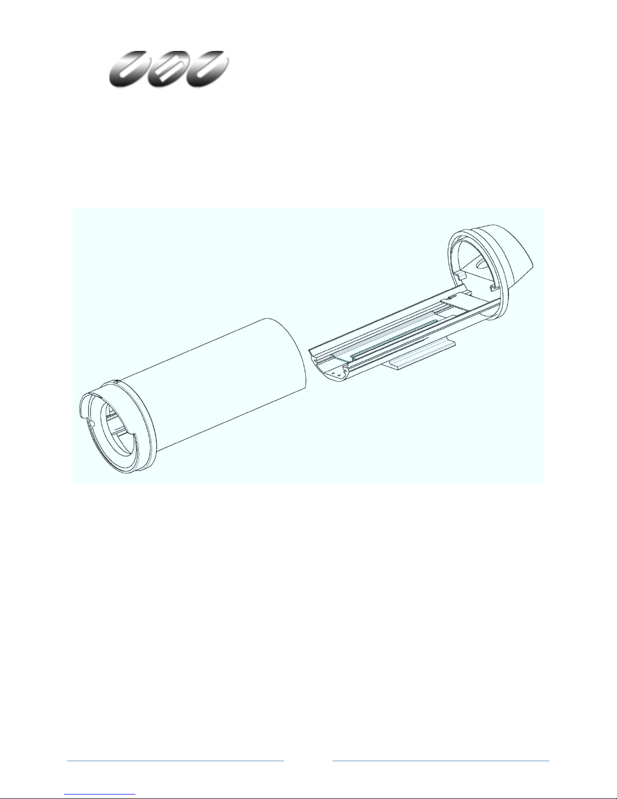
Instruction Manual - H4 Security Camera Housing w/Heater & Blower
These housing are designed with ease of installation and excellent environmental performance
in mind. With cable entry options through the rear cap and the mounting foot, these features
will allow for a variety of installation options. The accompanying mount permits cable
concealment when the cables are routed through the mount.
The all-aluminum construction is coated with a light colored UV protected power paint for
minimum heat absorption and environmental sealed with all UV protected silicone gaskets. The
3mm glass viewing window provides for HD optical clarity that will not fad or yellow over time.
Sized to fit a varying range of cameras and lenses, these housing provide a perfect complement
to most complete security and surveillance system solutions. Contact your security dealer or
customer service representative to match the best equipment and devices for your application.
Page 1
Page 2

IMPORTANT SAFEGUARDS
1. Read Instructions - All the safety and operating instructions should be read before the unit is operated.
2. Retain Instructions - The safety and operating instructions should be retained for future reference.
3. Heed Warnings - All warnings on the unit and in the operating instructions should be adhered to.
4. Follow Instructions - All operating and use instructions should be followed.
5. Cleaning – Disconnect from power source before cleaning. Use a damp cloth for cleaning.
6. Do not use attachments not recommended by the product manufacturer as they may cause hazards.
7. Power Sources - This unit should be operated only from the type of power source indicated on the marking
label. If you are not sure of the type of power supply you plan to use, consult your appliance dealer or local power
company. For units intended to operate from battery power, or other sources, refer to the operating instructions.
8. Grounding or Polarization - This unit may be equipped with a polarized current line plug. This plug will fit into
the power outlet only one way. This is a safety feature. If you are unable to insert the plug fully into the outlet, try
reversing the plug. If the plug should still fail to fit, contact your electrician to replace obsolete outlet. Alternately,
this unit may be equipped with a 3-wire grounding-type plug, a plug having a third (grounding) pin. This plug will
only fit into a grounding-type power outlet. This is a safety feature. If you are unable to insert the plug into the
outlet, contact your electrician to replace your obsolete outlet. Do not try to defeat these safety features.
9. Power-Cord Protection - Power-supply cords should be routed so that they are not likely to be walked on or
pinched by items placed upon or against them, paying particular attention to cords and plugs, convenience
receptacles, and the point where they exit from the appliance.
10. Power Lines - An outdoor system should not be located in the vicinity of overhead power lines or other electric
light or power circuits, or where it can fall into such power lines or circuits. When installing an outdoor system,
extreme care should be taken to keep from touching such power lines or circuits as contact with them might be
fatal. U.S.A. models only - refer to the National Electrical Code Article 820 regarding installation of CATV systems.
13. Overloading - Do not overload outlets and extension cords as this can result in a risk of fire or electric shock.
12. Object and Liquid Entry - Never push objects of any kind into this unit through openings as they may touch
dangerous voltage points that could result in a fire or electric shock. Never spill liquid of any kind on the unit.
13. Servicing - Do not attempt to service this unit yourself as opening or removing covers may expose you to
dangerous voltage or other hazards. Refer all servicing to qualified service personnel.
14. Replacement Parts -When replacement parts are required, be sure the service technician has used replacement
parts specified by the manufacturer or have the same characteristics as the original part. Unauthorized
substitutions may result in fire, electric shock or other hazards.
15. Coax Grounding - If an outside cable system is connected to the unit, be sure the cable system is grounded.
U.S.A. models only--Section 810 of the National Electrical Code, ANSI/NFPA No.70-1981, provides information with
respect to proper grounding of supporting structure, grounding of the coax to a discharge unit, size of grounding
conductors, location of discharge unit, connection to ground, and requirements for the grounding electrode.
FCC INFORMATION
WARNING - This equipment complies with the limits for a Class B digital device, pursuant to Part 15 of the FCC
Rules. Limits are designed to provide reasonable protection against harmful interference when the equipment is
operated in a residential installation. This equipment generates and can radiate radio frequency energy, if not
installed and used in accordance with the instructions, may cause harmful interference to radio communications.
However, there is no guarantee that interference will not occur in a particular installation. If this equipment does
cause harmful interference to radio or television reception, which can be determined by turning the equipment off
and on, the user is encouraged to try to correct the interference by one or more of the following measures:
- Reorient or relocate the receiving antenna or increase the separation between the equipment and receiver.
- Connect the equipment into an outlet on a circuit different from that to which the receiver is connected.
- Consult the dealer or an experienced radio/TV technician for help.
Intentional or unintentional changes or modifications not expressly approved by the party responsible for
compliance shall not be made. Any such changes or modifications could void the user's authority to operate the
equipment. The user may find the following booklet prepared by the Federal Communications Commission helpful:
"How to Identify and Resolve Radio-TV Interference Problems", available from U.S. Government Printing Office,
Washington, DC 20402, Stock No. 004-000-00345-4.
Page 2
Page 3

1. UNPACKING
Loosen
Do Not
Grasp Here
Slide
Unpack carefully. This equipment should be handled with care.
Check for the following items:
• Verify the unit model number.
• Verify that parts listed below have been included.
If an item appears to have been damaged in shipment, replace it properly in its carton and notify the shipper. If
any items are missing, notify your dealer or manufacture’s Sales Representative or Customer Service. The shipping
carton is the safest container in which the unit may be transported. Save it for possible future use.
Hardware Kit
2 x ¼-20 x 3/8” Hex Cross Recessed Head Screws
1 x ¼” Flat Washer
1 x ¼” Lock Washer
2. INSTALLATION
Tools required:
#2 Cross Recessed Screwdriver (Phillips)
1/8” Width Flat Blade Screwdriver
3/4” Open End Wrench
General Purpose Wire Stripper with Cutter
Optional: Adjustable Wrench
Materials required:
Outdoor Rated Cables for Power and Video
Cables must be round in shape with an outer jacket diameter of 0.170” minimum to 0.310” maximum.
1. Choose desired location for camera housing installation. Verify mounting structure and surface is capable of
supporting the camera and no obstacle or interference is present from existing installed devices or wiring.
2. Open housing by loosen the 2 Phillips head screws located on the
rear cap. Do not remove the lower two screws on the rear cap.
3. Holding the housing base securely, grasp front cap and cover,
pull forward sliding the cover off the base.
These
Screws
Remove
4. Remove camera mounting bracket by loosen two retaining screws. Slide and lift bracket.
5. Attach camera and lens to bracket using ¼-20 screw. The position of the camera can be adjusted by flipping
the bracket. The lens must not extend more than ¾” (0.750”) beyond the front edge of the bracket.
6. Choose cable entry path for power and video. Using ¾” wrench, install cable gland fittings either in the rear
cap or mounting foot depending on the entry point chosen. Install plugs in the holes not used for cable entry.
Page 3
Page 4

7. Attach power to connector terminal block. 24Vac power supply must
Construction
UV Protected Powder Coated Aluminum Body, Front and Rear Caps;
UV Protected Silicone Seals; Glass Window for HD Optical Clarity
Color Cool Gray (Pantone 1C)
Power 24Vac; w/heater & blow e r 11Watts; 460mA @ 24Vac
Operating Temerature w/heater and sunshield -40 ~ 55C
Storage Temerature -65C to 65C
Weight - Product 2.6-lbs w/out camera and lens
Weight - Shipping 3.0- l bs
Size 4.4"H x 4. 35"W x 11.6"L
MECHANICAL
be connected to terminals 2 and 3. Ground can be connected to
terminal N.
8. Position camera into housing and attach back and white wires to
camera power terminal as recommended by the camera manufacture.
9. Attach video cable to camera or other device as specified by the
camera or device manufacture.
10. Position cables to relieve excess stress and tighten the cable gland
fittings using ¾” wrench.
11. Slide cover into place, tighten two Phillips head screws to secure.
12. Attach housing to mounting bracket and set position.
3. SERVICE
If the unit ever needs repair or service, please contact the dealer or manufacture’s sales representative.
4. CARE AND MAINTENANCE
If the unit needs cleaning, use a soft damp cloth to wipe the external cover and viewing window.
5. ACCESSORIES
Recommended:
WB1 – Wall Mounting Bracket with feed through Adjustable Head feature
SS1 – Sunshield to promote cooling by protecting the housing from direct sunlight
6. SPECIFICATIONS
Page 4
 Loading...