

Page 1
ZC-NH406P
COLOR CCD CAMERA
INSTRUCTION MANUAL
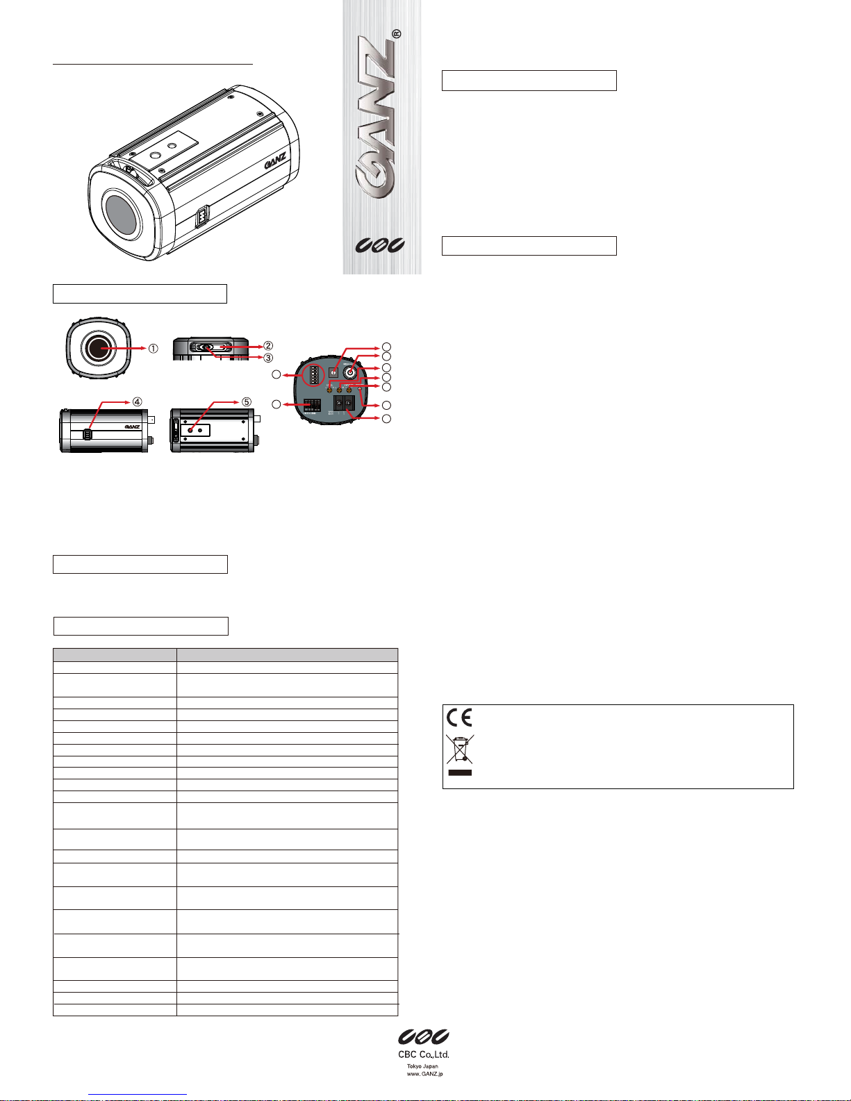
PART DESCRIPTION
(1) CS lens mount
(2) Back Focus adjustment lever
(3) Back Focus lock screw
(4) DC auto iris connector
(5) Mounting screw hole, 1/4”, 7mm deep
(6) DIP Switches
(7) Video auto iris and IR Lamp connector
(8) MES Switches
(9) BNC connector for video output
(10) ALC Level adjustment potentiometer
(11) ALC adjustment potentiometer
(12) V-Phase adjustment potentiometer
(13) LED lamp
(14) Power input terminal
Thank you for your purchase of this product.
Before operating the product, please read this instruction manual carefully to
ensure proper use of the product.
Please store this instruction manual in a safe place for future reference.
The installation should be made by a qualified service person or system installers
and should conform to all local codes.
If an abnormality should occur, immediately turn off the power and contact qualified
service professionals for instruction.
WARNING
•
Use only 24VAC or 12VDC regulated power supply marked class 2.
To prevent fire or electrical shark, UL listed class 2 wiring should be used for the
power input terminal.
•
Use only power source and connectors that have been approved in your country
and comply with the international standards.
•
Be sure to connect each lead to the appropriate terminal. Wrong connection may
cause malfunction and/or damage to the video camera.
•
Do not attempt to aim the camera at the sun or other extremely bright objects
that cause smear to appear irrespective of whether the camera is operating or
not. This can damage the CCD (Charge Coupled Device).
•
Do not place the camera in the following locations
- Locations subject to extremely high or low temperatures.
(Operating temperature range: -10°C to +50°C {14°F to 122°F})
(Storage temperature range: -20°C to +60°C {-4°F to 140°F})
- Locations subject to high levels of humidity and dust.
(Operating humidity range: max 85% {No condensation})
(Storage humidity range: max 95% {No condensation})
- Locations where there are large amounts of water vapor and steam.
•
Ensure the location selected is sufficiently strong enough to support the weight of
the camera and is free from vibration.
•
When this camera is installed near equipment that emits a strong electromagnetic
field, some irregularity such as noise on the monitor screen may happen.
•
Be sure to use screws suitable for the type of material to which the camera is being
mounted.
•
Do not allow the camera to be subjected to strong impacts or shocks. The camera
could be damaged by improper handling or storage.
•
Never attempt to disassemble or modify the camera.
•
If an abnormality should occur, immediately turn off the power and consult your
dealer.
•
When the camera is not in use, put the lens cap on to protect the CCD
sensor.
FEATURES
SAFETY PRECAUTIONS
CAUTION
To prevent fire or electrical shock, do not expose this appliance to rain or moisture.
1 When this crossed-out wheeled bin symbol is attached to a product it means the product is covered
by the European Directive 2002/96/EC.
2 All electrical and electronic products should be disposed of separately from the municipal waste
stream via designated collection facilities appointed by the government or the local authorities.
3 The correct disposal of your old appliance will help prevent potential negative consequences for the
environment and human health.
4 For more detailed information about disposal of your old appliance, please contact your city office,
waste disposal service or the shop where you purchased the product.
The CE Marketing is a Directive Conformity mark of the European Union (EU)
Camera (1)
Instruction Manual (1)
CCD Protection Cover (1)
PACKAGE
SPECIFICATION
099-1.0
L.L
TDN
BLC
AGC
AWB
TDN
INT
ON
ON
TURBO
AWB-EX
HI
ALC
GND
+12V
VIDEO
GND
LAMP
12
12
13
13
1
2
3
4
5
6
7
8
9
0
50/60 AES 100K
250
F.L.4K10K
Shutter Speed
500 1K 2K
14
14
6
7
8
9
10
10
11
11
Model
TV System
Image Sensor
Effective Picture Element
Horizontal Resolution
Synchronization
Scanning System
Scanning Frequency
S/N Ratio
AGC Control
Operating Temperature
Storage Temperature
Video Output
Power Supply
Power Consumption
IRIS Connector
Automatic
Electronic Shutter (second)
Manual
Electronic Shutter (second)
Minimum Illumination
Auto White Balance
Back Light Compensation
Dimensions
Weight
ZC-NH406P
PAL
1/3” Format
Interline CCD Sensor
752(H) x 582 (V)
540 TV line
Internal / Line Lock
2:1 Interlace
H:15625Hz V:50.0Hz
48 dB
Normal / Turbo
-10ºC to +50ºC
-20ºC to +60ºC
Composite video signal,
1V(p-p), 75Ω (BNC)
DC / AC 50Hz,
12VDC / ~24VAC ± 10%
4.5W Max.
4 pin Connector for DC Drive Lens /
3 Pin Terminal Block for Video Drive Lens
Auto illumination Control
1/50 - 1/100000
1/50, 1/120 FLK, 1/250, 1/500,
1/1K, 1/2K, 1/4K, 1/10K, 1/100K
Day : 0.3 lx @ F1.2
Night : 0.1 lx @ F1.2
Normal : 2700°K ~ 9700°K
Extra : 2000°K ~ 18000°K
Off / On
62mm (W) x 58mm (H) x 120mm (L),
260 g (without lens)
•
Day and night function provide high quality color picture in the normal lighting
conditions (day mode) and a high sensitivity black & white picture in the low light
conditions (night mode) by switching IR cut filters.
•
540 TV line horizontal resolution
•
DIP switches allow users to set up various parameters easily including Line Lock,
Day/Night mode, back light compensation, and Manual Shutter Speed switch.
•
Low image distortion and residual, withstanding electric and magnetic field
interference and mechanical vibration.
•
Signal to noise ratio of 48dB.
•
Minimum illumination of 0.1 lx.
•
Accurate color reproduction.
•
Easy backfocus adjustment function allows quick installation.
Page 2
1. Loosen the back focus adjustment lever located
on the front head.
2. Adjust the screw to a desired position, and then
fix the screws.
Caution for focus adjustment:
1. Do not over-tighten the back focus screw.
2. Do not attempt to use any tools other than fingers to tighten the screw.
Improper focus adjustment may result in severe damages to the back-focus
echanism or to the CCD image sensor.
Focus Adjustment
→ refer to PARTS DESCRIPTON (2) & (3)
Connect the power cable to the power input connector or terminal on the rear panel.
The camera automatically detects the power source (DC12V/AC24V).
Make sure the proper polarity for DC source.
Use RED terminal for +12VDC and BLACK for ground connection.
Improper polarity may cause damage to camera.
The Power LED on the rear panel is lit when the camera is connected to a power
source (refer to Parts Description 13).
Important Note:
Qualified service personnel or system installers should perform the installation.
Make sure that the power is OFF before handling the power supply cable.
Connect the 75Ω coaxial cable to video output terminal.
This camera supports manual iris lens, video auto iris lens,
and DC auto iris lens.
1. Video Auto Iris Lens Pin assignment
GND: Shield, ground.
+12V: Power source; +12VDC, 50 mA Max.
Video: Video signal output.
2. DC Auto Iris Lens
The 4 pin connection terminal is on the
rear panel. Refer to the pin assignment
to ensure the proper operation.
1. Mount a lens onto the camera lens mount. Turn the lens clockwise.
2. This camera can accept CS-mount lens, or C-mount lens with a 5 mm adaptor ring.
Cautions for lens mounting:
1. In case of using a lens heaver than the camera, the lens and camera will require
additional support.
2. Do not over-tighten the lens onto the camera mount.
3. Do not rotate the lens counter-clockwise.
Lens Mounting
→ refer to PARTS DESCRIPTON (1)
CONNECTION AND ADJUSTMENT
Power Supply Cable Connection
→ refer to PARTS DESCRIPTON (14)
Video Cable Connection
→ refer to PARTS DESCRIPTON (9)
Auto Iris Lens Connections
→ refer to PARTS DESCRIPTON (4) & (7)
GND
LAMP
This camera is equipped with an external contact terminal
in order to prevent a mechanical Optical Low pass
Filter hunting in infrared illumination.
Connecting it to GND immediately switches the mode
from daytime to nighttime.
Caution
When using an IR lamp, be sure to use an infrared compatible lens
(Day & Night lens) to ensure proper focusing in IR illuminated settings.
LAMP Contact Terminal
GND
+12V
VIDEO
POTENTIOMETER SETTING
WB-EX
I
ALC
50/60 AES 100K
→ Refer to PARTS DESCRIPTION (10), (11) & (12)
•
LEVEL (Auto Lens Control Level Adjustment)
This potentiometer controls DC lenses:
it manages CCD sensor light quantity by adjusting
lens IRIS aperture.
•
ALC (Auto Lens Control Adjustment)
This potentiometer controls auto iris drive, which is supplied to DC drive lens.
Make sure that the connection is correct before adjustment.
•
V-Phase (Line Lock Phase Adjustment)
When the camera is set to Line-Lock mode (LL), it is possible to adjust camera
triggering point on the AC cycle in case of systems using sequential switchers
devoid of image digital process feature or video matrixes.
See also ’DIP SWITCH SETTING’ (LL/INT) paragraph above.
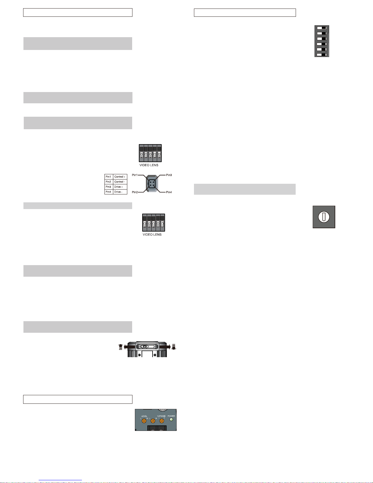
DIP SWITCHES SETTING
L.L
TDN
BLC
AGC
AWB
TDN
INT
ON
ON
TURBO
AWB-EX
HI
→ Refer to PARTS DESCRIPTION (6)
The row of DIP switches allow the following settings
to be made:
•
LL / INT
The line-lock mode enables the AC line
phase adjustment.
Note:
The line-lock sync mode is not available when the camera operates on DC power.
•
TDN / ON
This feature enables the camera operates in monochrome mode in
reduced lighting.
Switch to ON to activate.
•
BLC / ON
The Backlight Compensation feature eliminates the effect of strong background
lighting, maintaining the correct exposure. Switch to ON to activate.
When switched to BLC, the feature is off.
•
AGC / TURBO
The Automatic Gain Control feature can improve picture quality in
low lighting conditions.
Select TURBO for most applications.
Setting to AGC will reduce 'noise' from the image, but it will also limit the
camera's sensitivity.
•
AWB / AWB-EX
AWB: The camera operates in the normal Auto White Balance range
2700°K ~ 9700°K
AWB-EX: The camera operates in the extended Auto White Balance range
2000°K ~ 18000°K.
•
TDN / HIGH
The TDN mode can be activated only when TDN switch is set to “ON”.
When set “HI”, the camera will switch to Night (Monochrome) mode
at a lower light level.
Shutter Speed Setting (MES)
→
refer to PART DESCRIPTION (8)
You can select the manual shutter speed of
1/50, 1/120 FLK or 1/120 FLK, 1/250, 1/500, 1/1K, 1/2K,
1/4K, 1/10K, 1/100K seconds, or
Auto Electronic Shutter (AES).
Turn the switch to the to the Shutter parameter (1~9) and
select a desirable electronic shutter speed.
Set to “0” is for AES.
1
2
3
4
5
6
7
8
9
0
50/60 AES 100K
250
F.L.
4K
10K
Shutter Speed
Shutter Speed
500 1K 2K
 Loading...