

Page 1
Before attempting to connect or operate this product, please read these instructions completely.
Page 2

Preface
The information provided in this manual was current when published. The company reserves the
right to revise and improve its products. All specifications are subject to change without notice.
Notice
To work with the CCTV system control keyboards, any installer or technician must
have the following minimum qualifications:
• A basic knowledge of CCTV systems and components
• A basic knowledge of electrical wiring and low-voltage electrical connections
• Thorough familiarity with the contents of this manual
Important Information
Before proceeding, please read and observe all instructions and warnings in this
manual. Retain this manual with the original bill of sale for future reference and, if
necessary, warranty service. When unpacking your unit, check for missing or
damaged items. If any item is missing, or if damage is evident, DO NOT INSTALL
OR OPERATE THIS PRODUCT. Contact your dealer for assistance.
Copyright
Under copyright laws, the contents of this user manual may not be copied,
photocopied, translated, reproduced or replicated in any electronic medium or
machine-readable format, in whole or in part, without the prior written permission of
CBC Co. Ltd.
©Copyright2006CBC Co. Ltd.
Regulation
This device complies with Part 15 of the FCC Rules. Operation is subject to the
following two conditions:
(1) this device may not cause harmful interference, and (2) this device must accept
any interference received, including interference that may cause undesired
operation.
1
Page 3
Warning Notices
• Do not expose the product to rain or moisture
To prevent fire or electric shock, do not expose the product to rain or
moisture
• Do not dismantle this product
To prevent the risk of electric shock, do not dismantle the product. There
are no user serviceable parts inside.
• Clean the equipment carefully.
A dry cloth is recommended for cleaning.
!
This equipment generates and radiates radio frequency energy. It may cause
harmful interference to radio communication if it is not installed and used in
accordance with the instruction manual. This equipment has been tested and
found to comply with the limits for a Class A computing device pursuant to
subsection J of section 15 of the FCC regulations, which are designed to
provide reasonable protection against harmful interference when operated in
a commercial environment. This equipment has also been tested and found to
comply with the requirements of the CE Class A device safety standards.
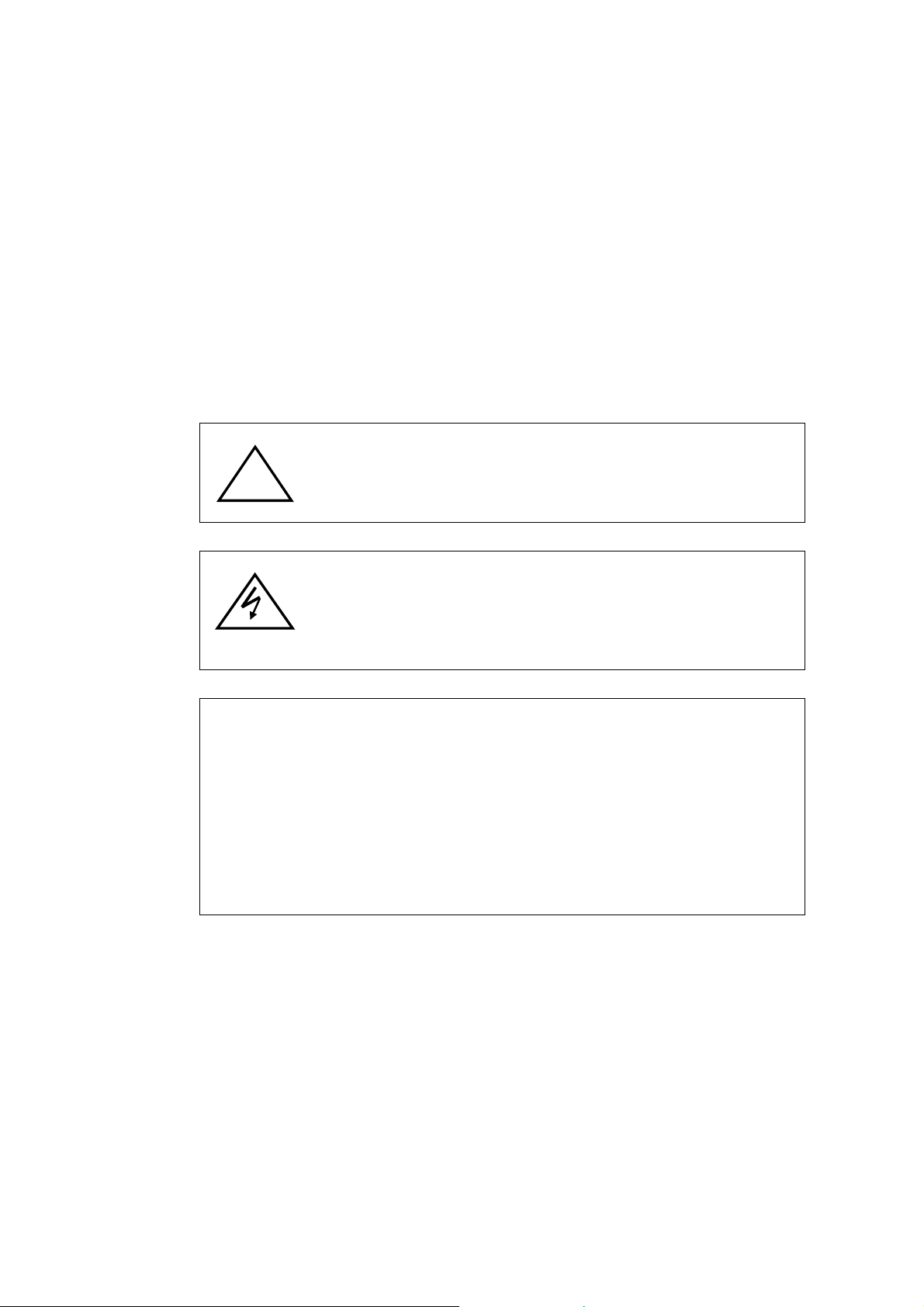
The exclamation mark in an equilateral triangle is intended to
alert the user to the presence of important operating and
maintenance (servicing) instructions in the literature
accompanying the products
The lightning flash with the arrowhead symbol in an equilateral
triangle is intended to alert the user to the presence of
uninsulated ’’dangerous voltage’’ within the product housing
that may be of sufficient magnitude to constitute a risk of
electric shock to persons.
NOTE
00-373130CSEA2
2
Page 4

Contents
1. Overview..............................................................................................................................5
2. Product Features ................................................................................................................6
3. Function Keys and Connectors.........................................................................................7
3.1 Front Panel...............................................................................................................................7
3.2 Rear Panel................................................................................................................................8
4. System Connection and Power Up ...................................................................................9
4.1 Connecting RS-485 Cables ....................................................................................................9
4.2 Powering Up the Devices ....................................................................................................... 9
4.3 Standby Mode Actions..........................................................................................................10
5. Keyboard System Settings ..............................................................................................11
5.1 Keyboard ID Assignment...................................................................................................... 11
5.2 GANZ PTZ Camera Control .................................................................................................. 11
5.3 GANZ-S Protocol Baud Rate Setting................................................................................... 12
5.4 System Date Setting..............................................................................................................12
5.5 System Time Setting.............................................................................................................12
5.6 System Alarm List .................................................................................................................12
5.7 Camera Setting......................................................................................................................13
5.8 Key Press Beep ..................................................................................................................... 13
5.9 Alarm Response....................................................................................................................13
5.10 Password Setting .................................................................................................................. 14
5.11 Key Lock ................................................................................................................................14
6. PTZ Camera Control.........................................................................................................15
6.1 Enter Camera OSD Menu...................................................................................................... 15
6.2 Joystick ..................................................................................................................................15
6.3 Preset Function ..................................................................................................................... 16
6.4 Sequence Function ...............................................................................................................16
6.5 Auto-pan.................................................................................................................................17
6.6 Cruise .....................................................................................................................................18
6.7 Camera Lens Control............................................................................................................18
6.8 Auto Focus.............................................................................................................................19
7. DVR/Multiplexer Control ..................................................................................................20
7.1 Jog ..........................................................................................................................................20
7.2 Display....................................................................................................................................20
7.3 User.........................................................................................................................................20
7.4 Spot.........................................................................................................................................20
7.5 Menu .......................................................................................................................................20
7.6 Enter ....................................................................................................................................... 20
3
Page 5

Reverse Play ..........................................................................................................................21
7.7
7.8 Playback.................................................................................................................................21
7.9 Fast Forward..........................................................................................................................21
7.10 Rewind....................................................................................................................................21
7.11 Stop......................................................................................................................................... 21
7.12 Pause......................................................................................................................................21
7.13 Full Zoom ...............................................................................................................................21
7.14 Panorama ...............................................................................................................................21
7.15 PIP........................................................................................................................................... 21
7.16 Search ....................................................................................................................................21
7.17 PTZ.......................................................................................................................................... 21
7.18 Lens Control in DVR Control Mode .....................................................................................22
7.19 Auto Focus.............................................................................................................................22
7.20 Auto Sequence ...................................................................................................................... 22
7.21 Run Sequence .......................................................................................................................22
Appendix A: Specifications....................................................................................................23
Appendix B: Function Tree ....................................................................................................24
Appendix C: ID Address Mapping .........................................................................................26
Appendix D: Firmware Upgrade ............................................................................................27
4
Page 6
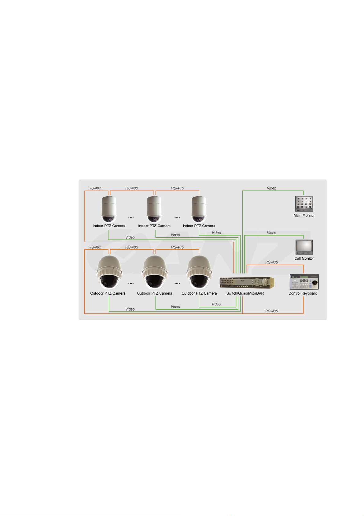
1. Overview
This CCTV system control keyboard can easily be integrated with our full range of
CCTV products, such as a digital video recorder, PTZ camera and other CCTV
devices with an RS-485 interface for remote control and system configuration. The
backlit LCD display and 3-axis control joystick provide user friendly operation.
Multiple protocols enable the user to integrate our products into existing systems
from other brands and extend the system connectivity. Built-in firmware upgrade
circuits allow the user to easily upgrade the firmware via the RS-232 port.
Connect PTZ cameras to other devices, such as a control keyboard, DVR, monitor
and alarm devices to create a complete surveillance system.
The use of a repeater is recommended if the system network distance exceeds 1.2
km (4000 feet). In this case, placing the repeater at the centre of the network
distance could help to maintain signals. Refer to the repeater user manual for
detailed information.
5
Page 7

2. Product Features
• CCTV device control
• Joystick control for PTZ functions
• Preset positions and pattern control
• User-friendly interface in LCD display
• Firmware upgrade available via RS-232 port
• Rubber keypad makes it easier to input commands
• Remote control via RS-485 interface
• PTZ cameras, multiplexers, P/T/Z receivers and all-in-one cameras can be
controlled using this keyboard
• Built-in clock for date and time recording
• Built-in clock synchronisation function for RS-485 devices
• Optional 3-dimensional joystick
• Multiple built-in protocols: Ganz-S, Ganz-PT, Pelco-D, Pelco-P and receiver
box
6
Page 8
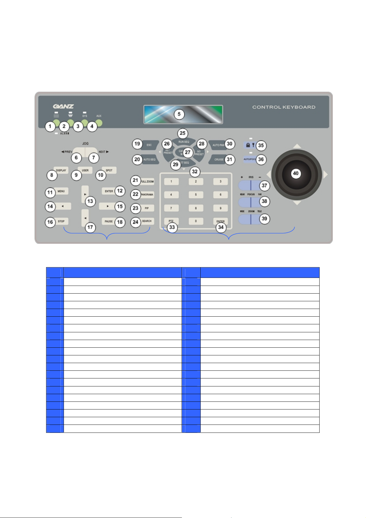
3. Function Keys and Connectors
3.1 Front Panel
DVR Control Buttons
Camera Control Buttons
No. Key Definition No. Key Definition
1 DVR/multiplexer mode selection 21 Full zoom: zoom in key
2 Camera/dome mode selection 22 Panorama (DVR mode)
3 System setup mode selection 23 PIP (DVR mode)
4 AUX: Reserved 24 Search (DVR mode)
5 LCD 25 Run SEQ & Up direction key
6 Jog prev. 26 Set preset & Left direction key
7 Jog next 27 Camera menu: enter OSD
8 Display 28 Move to preset & Right direction key
9 User 29 Set SEQ & Down direction key
10 Spot 30 Auto pan
11 Menu 31 Cruise
12 Enter (DVR mode) 32 Number keys
13 Fast forward & Up direction key 33 PTZ: PTZ mode under DVR control
14 Reverse play & Left direction key 34 Enter
15 Play & Right direction key 35 Key lock
16 Stop 36 Auto focus
17 Rewind & Down direction key 37 Iris control (N/A for Ganz-S protocol)
18 Pause 38 Focus near/far
19 ESC: Exit & back to previous menu 39 Zoom wide/tele
20 Auto SEQ (DVR mode) 40 Joystick
*Specifications are subject to change without notice
7
Page 9
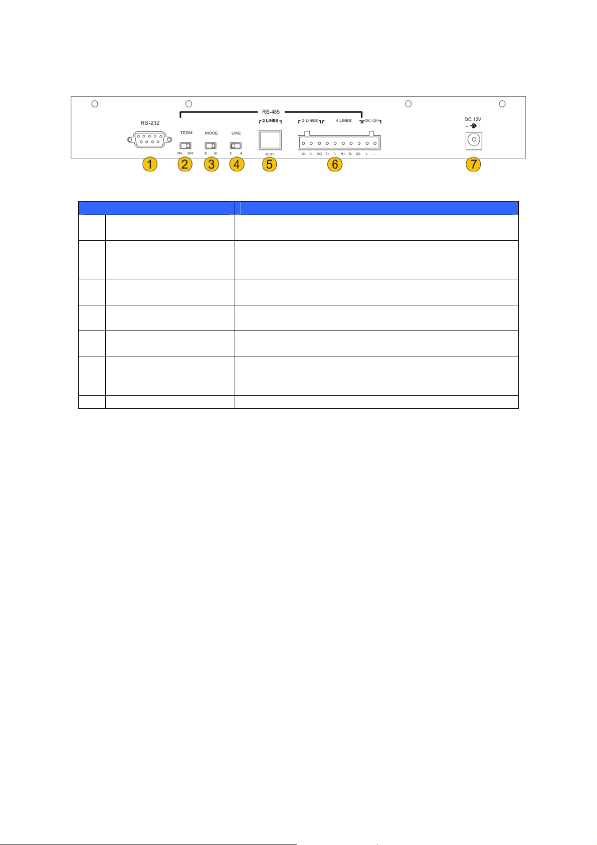
3.2 Rear Panel
Connector Description
RS-232 D-SUB
1
Termination switch
2
Mode switch
3
Line selection switch
4
RJ-11 jack
5
Terminal blocks
6
Power jack Use this jack for the keyboard power supply.
7
User can upgrade the keyboard firmware using this
port.
This switch is used to terminate the connected RS-485
communication line. It should normally be left in the
OFF position. The default is OFF.
This mode is used for factory setting. This switch
should be set to MASTER.
Please select 2-lines mode (half-duplex) for the RS-485
communication.
This jack is used for factory setting and should not be
used.
Use this terminal block to connect 2-lines RS-485
communication wires. Additional power input positions
are also available on this connector.
8
Page 10

4. System Connection and Power Up
The control keyboard can be connected to a PTZ camera or a digital video recorder
(DVR). The basic connections in a surveillance system are described below.
4.1 Connecting RS-485 Cables
To operate PTZ cameras, a control keyboard (or other control unit, e.g. DVR) is
needed to allow the PTZ camera to communicate with its control unit using the
RS-485 interface. CAT 5 (shielded twisted pair) cables are recommended for
RS-485 communication; the maximum cable length for wire with a gauge above 24
is 4000 feet (1219 meters). If the total cable length exceeds 4000 feet, using a
repeater to amplify the signals is recommended.
The terminal block is designed for long distance installations. The user can set up
an RS-485 network using the terminal block located on the rear panel of the control
keyboard. Detailed pin definitions can be found on rear panel.
4.2 Powering Up the Devices
Follow the steps below to power up all devices.
• Connect all devices. Before connecting the PTZ cameras and DVRS to
the system control keyboard, please complete all protocol and unit ID
settings.
• Power up all devices except for the keyboard. Make sure the images
from the cameras are displayed on the monitor screen.
• Power up the control keyboard.
As soon as the control keyboard is powered up, the software version is displayed on
the LCD as shown below.
CCTV Controller
Version x.xx
The keyboard LCD will display the date and time when the keyboard is in standby
mode.
CCTV Keyboard
2005/12/15 12:00:00
9
Page 11

4.3 Standby Mode Actions
The user can perform the following actions in standby mode.
• Press the <SYS> key to enter System Setup mode.
• The user can enter Camera Control mode by pressing the
<Camera/Dome Mode> key
. This mode enables pan, tilt, zoom
operation, camera OSD setup and other PTZ camera controls to be
carried out.
• The user can enter DVR/Multiplexer Control mode by pressing the
<DVR/Multiplexer Mode> key
.
For detailed instructions on keyboard system settings, PTZ camera control and DVR
control, refer to the following sections.
10
Page 12

5. Keyboard System Settings
The keyboard will enter System Setup mode when the user presses the <SYS> key
and enters a correct password (default password is 0000). Detailed operation will be
described in the following sections. Use the ▲(RUNSEQ) and ▼(SETSEQ) keys to
scroll through the setup options.
1.0 System Setting
Enter password [____]
5.1 Keyboard ID Assignment
This option allows the user to assign a new ID for this keyboard. Press the ◄ or ►
key to change the ID number. The default ID for the control keyboard is 240.
1.1 Set Keyboard ID
(240-254):240
NOTE: No two control keyboards connected to the same RS-485 bus should
be given the same ID.
5.2 GANZ PTZ Camera Control
There are two kinds of PTZ camera control mode. The user can press the right and
left direction keys in this setup menu to choose the control method – direct camera
control bypassing the connected DVR or through the DVR.
1.2 Camera Control
a. Bypass DVR
NOTE: “Bypass DVR” means that control command signals will be sent
directly to PTZ cameras. The user can simply enter the PTZ camera ID
directly and operate the camera.
1.2 Camera Control
b. Through DVR
NOTE: “Through DVR” means that control command signals will be sent to
the DVR, and the DVR will transfer these commands to the PTZ camera to
execute the relevant operation. Generally, we do not recommend controlling
cameras through a DVR in order to avoid any interference that can occur during the
process.
11
Page 13

5.3 GANZ-S Protocol Baud Rate Setting
This option enables the user to change the baud rate for Ganz-S protocols. The
options are 4800, 9600, 19200 and 38400 bps; the factory default is 9600 bps.
1.3 Ganz Baudrate
b. Baud rate 9600bps
5.4 System Date Setting
This option allows the user to set the control keyboard system date. Press the ◄
and ► keys to select a column (year, month and date) to modify, and input the new
system date directly using the number keys located on the control keyboard. Press
the <ESC> key when finished to exit this mode.
1.4 Date Setting
Press ENTER for Setup
1.4.1 Date Setting
YY:xx Mth:xx Day:xx
5.5 System Time Setting
This option allows the user to set the control keyboard system time. Press the ◄
and ► keys to select a column (hour, minute and second) to modify, and input the
new system time directly using the number keys. Press the <ESC> key to exit this
mode.
1.5 Time Setting
Press ENTER for Setup
1.5.1 Time Setting
hh:xx mm:xx ss:xx
5.6 System Alarm List
This option enables the user to list the 10 most recent alarm information messages
from the system bus, including the event trigger time and the triggered camera ID.
Press <ESC> to exit this mode.
1.6 Alarm List
Press ENTER for Setup
1.05/11/20 13:08:02
Alarm camera ID: xxx
12
Page 14

5.7 Camera Setting
This option allows the user to assign an appropriate individual protocol to the
keyboard for each camera. Press <1> to start protocol assignment. Press the ◄ or
► keys to change the setting and the ▲ or ▼ keys to select a camera. Press
<ESC> when finished. The available protocols are Ganz-S, Ganz-PT, Pelco-D,
Pelco-P and Chiper.
Protocol Baud Rate
Ganz-S 4800, 9600, 19200 and 38400 bps (in keyboard system setting)
Ganz-PT 9600 bps
Pelco-D 2400 bps
Pelco-P 4800 bps
Chiper For receiver box, baud rate 9600 bps
NOTE: Ganz-PT is for ZC-PT series PTZ camera. Ganz-S is for ZC-S series
1.7 Camera Setting
Please Press 1
1.7.1 Camera ID #001
Pelco-P [GANZ-PT] ►
PTZ camera.
5.8 Key Press Beep
This option enables the user to turn the key beep on and off. If the setting is ON, the
key beeps when pressed. Press the ◄ or ► key to change the setting.
1.8 Key Press Beep
[OFF] ON
5.9 Alarm Response
The control keyboard can be programmed to execute the following actions if the
control keyboard receives alarm signals from a PTZ camera.
• Buzzer beep
• Link to the PTZ camera that broadcast this alarm message
• Switch the video channel to full screen from multiplexer
This option is used to enable or disable the keyboard's alarm response function.
The default is OFF. Press the ◄ or ► key to change the setting.
1.9 Alarm Response
[OFF] ON
13
Page 15

5.10 Password Setting
This option enables the user to change the password for the keyboard. The user
must correctly input a new 4-digit password twice to confirm the password change.
5.11 Key Lock
If this key is pressed and held for three seconds, the keys on the control
keyboard will be locked and the LED will be lit. To unlock the keys, press and
hold the key again for three seconds.
1.10.1 Password[****]
1.10.2 Password[****]
Confirm[___]
14
Page 16

6. PTZ Camera Control
To enter Camera Control mode, press the <Camera/Dome Mode> key , input
the ID of the PTZ camera you want to operate, and press <ENTER> to confirm.
Camera Control
Enter camera no:xxx
The control keyboard enters Camera Control mode when the user selects a camera
and all of the camera's functions can then be controlled.
xxx Ganz PT Camera
___
The first row displayed in the LCD contains information about the selected camera
type. The second row in the LCD allows the user to input a preset point number
(1~256) or other camera parameters. Detailed operating instructions are set out in
the following sections.
The camera name displayed in the first row will be different depending on the
protocol used. It could be “Ganz-S Camera”, “Ganz PT Camera”, “PelcoD Type
Came” or “PelcoP Type Came”, which indicates that the PTZ Camera is using
Ganz-S, Ganz-PT, Pelco-D or Pelco-P protocol relatively.
6.1 Enter Camera OSD Menu
Press the <CAMERA MENU> key to open the OSD menu for the PTZ camera if the
selected camera is equipped with an OSD function. Once the OSD menu has been
opened, the user can move the OSD bar using the direction keys on the keyboard.
For full details of the PTZ camera OSD setup, refer to the relevant camera
documentation.
NOTE: For Ganz-S protocol. The keyboard LCD displays “OSD ON” while
the control keyboard is under OSD setup menu mode, and the message
“TURN KEYBOARD OSD OFF” displaying on the monitor reminds the user to turn
off the OSD menu manually by pressing <CAMERA MENU> for three seconds.
xxx Ganz-S Camera
6.2 Joystick
Push joystick right/left/up/down to directly pan/tilt the PTZ camera.
OSD ON
15
Page 17

6.3 Preset Function
In Camera Control mode, the user can operate the preset function. Follow the
instructions below to set and execute preset points.
xxx Ganz PT Camera
___
■ Set Preset Point
Press a number key, e.g. <2>, for a view area, and then press <SET PRESET> to
enter this position as preset point 2.
xxx Ganz PT Camera
Set Preset 002 . . .___
■ Go To Preset Point
Press a number key, e.g. <2>, and then press <GO PRESET> to move to the
defined preset position.
xxx Ganz PT Camera
Go Preset 002 . . .___
6.4 Sequence Function
In Camera Control mode, the user can operate the sequence function. Up to eight
sequence lines can be programmed into the ZC-PT2XX using the OSD menu, and
the first four sequence lines can be executed directly via the keyboard. Follow the
instructions below to manipulate this function.
■ Setting Sequence Line
Press <CAMERA MENU> to enter the OSD setup menu and set up the sequence
lines as described in the camera operating instructions. The sequence setup
menu for the PTZ camera is as shown below.
SEQUENCE
SEQUENCE LINE 1
SEQUENCE POINT 01
PRESET POSITION 001
SPEED 1
DWELL TIME 001
RUN SEQUENCE ENTER
EXIT YES
16
For more details refer to the GANZ ZC-PT2XX series camera manuals.
Page 18

■ Executing Sequence Function
Press <1> and <RUN SEQ.> to execute the first sequence line defined in the
OSD; the first 4 sequence lines can be executed directly from the keyboard. To
set the other sequence lines, complete the setup and execute them in the OSD
menu.
xxx Ganz PT Camera
6.5 Auto-pan
In Camera Control mode, the user can control the built-in auto-pan function on the
ZC-PT2XX. Follow the instructions below to manipulate this function.
■ Setting Auto Pan Function
Up to 4 auto-pan lines can be set up in the OSD menu. Press <CAMERA
MENU> to enter the OSD setup menu and set up the auto-pan lines as
described in the camera operating instructions. The auto-pan setup menu for
the PTZ camera is as shown below.
Running Sequence 1
AUTOPAN
AUTOPAN LINE 1
START POINT TO FIND
END POINT TO FIND
DIRECTION RIGHT
SPEED 1
RUN AUTOPAN ENTER
EXIT YES
Only the first auto-pan line can be set directly from the control keyboard; press
<AUTO PAN> and select <2> to configure.
3.0 Autopan Select
1.Run 2.Setting
■ Execute Auto-Pan function
The first auto-pan line can be executed directly from the keyboard; the other
three can be executed using the OSD menu. Press <AUTO PAN> and then
<1> to execute the first auto-pan line defined in the OSD menu.
3.0 Autopan Select
1.Run 2.Setting
xxx Ganz PT Camera
Running Auto Pan…
17
Page 19

For detailed instructions on setting auto-pan lines, refer to the PTZ camera user
manual.
6.6 Cruise
In Camera Control mode, the user can control the built-in cruise function on the
ZC-PT2XX series. Follow the instructions below to manipulate this function.
NOTE: If the camera uses Ganz-S protocol, the user is only allowed to
pan/tilt the camera when setting Cruise line.
■ Setting Cruise Function
Press <CAMERA MENU> to enter the OSD setup menu and set up the cruise
line as described in the camera operating instructions.
■ Execute Cruise Function
Press the <CRUISE> key on the keyboard to execute the cruise function.
xxx Ganz PT Camera
Running Cruise…
6.7 Camera Lens Control
In Camera Control mode, the user can control the camera lens functions. The
function of the lens control keys is described below.
• Iris Function
<+>: Press to open the iris.
<->: Press to close the iris.
NOTE: This Iris adjustment is not available for ZC-S series camera.
• Zoom Function
<Tele>: Press to zoom the lens in.
<Wide>: Press to zoom the lens out.
• Focus Function
18
Press the focus keys to adjust the focus of the lens in manual focus mode.
Page 20

<Focus Near>: Press to move the lens focus closer.
<Focus Far>: Press to move the lens focus further away.
6.8 Auto Focus
Press the <Auto Focus> key to toggle the auto focus function and the LED will
be lit. When the user uses the lens control keys to manually operate the PTZ
camera, the auto focus LED will be turned off automatically.
19
Page 21

7. DVR/Multiplexer Control
The user can control the DVR/multiplexer remotely using the control keyboard.
Press the <DVR/Multiplexer Mode>
mode, enter the ID number of the DVR/multiplexer, and press the <ENTER> key to
confirm your input.
Refer to the DVR/multiplexer user manual for advanced control instructions.
7.1 Jog
If the connected DVR/MUX is in playback mode, press the right side
of the key (NEXT) to fast forward playback when paused. Press the
left side of the key (PREV) to rewind playback when paused. This
function key has a similar function to the jog dial on the front panel
of the DVR.
key to enter DVR/multiplexer control
DVR/MUX Mode
Select DVR(1-14):01
DVR/MUX: 01
CH: xx
7.2 Display
In DVR Control mode, the user can change the video image display format by
pressing the <DISPLAY> key on the control keyboard. The image toggles
between 1, 4, 9, 16 etc. split screens.
7.3 User
Enter user-defined screen mode. Use the <USER> key to toggle between 4, 9,
6, 7, 10, 13, 8 and PIP screens. Enter detail view while in recording schedule.
7.4 Spot
Enter SPOT mode to allow SPOT monitor control. The main monitor displays
the SPOT status indicator when the keyboard is in SPOT mode.
7.5 Menu
Press this key to enter the DVR OSD setup menu. In OSD setup mode, use this
key to complete the setup procedure and exit sub-menus.
7.6 Enter
In the DVR OSD setup menu, use this key to enter a sub-menu and select a
setup option.
20
Page 22

7.7 Reverse Play
In DVR control mode, press this key to reverse playback. The key can also be
used as the left direction key for panning PTZ cameras in PTZ control mode.
7.8 Playback
In DVR control mode, press this key for playback. The key can also be used as
the right direction key for panning PTZ cameras in PTZ control mode.
7.9 Fast Forward
In DVR control mode, press this key to fast forward during playback. Press
again to increase the speed. The user can also use this key as the up direction
key to tilt the PTZ camera in PTZ control mode.
7.10 Rewind
In DVR control mode, press this key to rewind during playback. Press again to
increase the speed. The user can also use this key as the down direction key to
tilt the PTZ camera in PTZ control mode.
7.11 Stop
In DVR control mode, use this key to stop playback or reset alarms and hold
down to select multiple cells in the recording schedule.
7.12 Pause
In DVR control mode, use this key to pause playback. Press the playback key
again to resume playback.
7.13 Full Zoom
This key enables a 2, 3 or 4 x zoom function. Use the direction keys to move
the zoom area.
7.14 Panorama
Play back a single channel on a multi-split screen. Use the <DISPLAY> key and
channel keys to adjust the viewing effects.
7.15 PIP
Picture-in-Picture mode allows you to view live and playback screens
simultaneously.
7.16 Search
The user can press this function key to select or search a video file to find a
specific date, time or event to play back.
7.17 PTZ
In the same way as when controlling cameras from the DVR front panel, to
control PTZ cameras in DVR mode the user must press this key to enter PTZ
mode.
21
Page 23

When the user presses the key, a PTZ flag will be displayed in the top right
corner of the screen.
In PTZ control mode, use the playback, replay, FF and RW keys to control the
PTZ camera pan and tilt.
7.18 Lens Control in DVR Control Mode
The user can control the functions of the lens using the lens control keys in PTZ
mode.
• Zoom Function
<Tele>: Press to zoom the lens in.
<Wide>: Press to zoom the lens out.
• Focus Function
Press the focus keys to adjust the focus of the lens in manual focus mode.
<Focus Near>: Press to move the lens focus closer.
<Focus Far>: Press to move the lens focus further away.
7.19 Auto Focus
When the user switches to DVR control mode, the auto focus LED will be turned
off immediately. Press this function key after manually adjusting the camera
lens to bring the image back into focus.
7.20 Auto Sequence
In DVR control mode, press this key to execute the defined sequence of monitor
displays.
7.21 Run Sequence
In PTZ mode, the user can execute the first sequence line set on the PTZ
camera. The function is similar to TOUR on the DVR front panel.
22
Page 24

Appendix A: Specifications
General Features
Environment
Controller interface
Operating temperature
Power source
Power consumption
Dimensions
Weight
Control Features
PTZ Camera
DVR/Multiplexer
Protocols supported
Indoor
RS-485
0° ~ 40 °C
DC 12V
5W
65mm (H) ×300mm (W) ×175mm (D)
1.5 kg
Lens control
Pan/tilt control
Mode selection Yes
Menu control Yes
Ganz-S Yes
Ganz-PT Yes
Pelco-D&P Yes
Chiper Yes (for receiver box)
Zoom: Tele/Wide
Focus: Near/Far/Auto
IRIS: Open/Close
Manual
Preset
Sequence
Cruise
Auto-pan
23
Page 25

Appendix B: Function Tree
■ PTZ Camera Control
Function Operation Description
Camera selection
Pan/tilt Joystick Right/left for pan, up/down for tilt
Lens control <Zoom Wide> Zoom out
<Zoom Tele> Zoom in
<Focus Near> Focus near
<Focus Far> Focus far
<Auto / Focus> Auto focus
Set preset <1> ~ <256> + <Set Preset> Record preset point
Call preset <1> ~ <256> + <Go Preset> Recall preset point
Sequence <1> ~ <4> + <Run SEQ> Execute sequence
Auto-pan <1> + <AUTO PAN> Execute auto-pan
Cruise <CRUISE> Execute the cruise set in OSD menu.
OSD open <Camera Menu> Press this key for 3 seconds to open OSD
+ <1> ~ <223>
■ DVR/Multiplexer Control
Function Operation Description
DVR/multiplexer
selection
Split screen display <DISPLAY> Toggles between 1,4,9,16,6,8,7
Defined screen mode <USER> Enter user-defined screen display mode
SPOT monitor control <SPOT> Allows control of SPOT monitor
Enter MUX/DVR OSD <MENU> Enter MUX/DVR OSD setup menu for
Search files <SEARCH> Search files by specific date, time and event.
Playback <PLAY> key Playback recorded image files
Reverse playback <R.PLAY> key Reverse playback of image files
Fast forward <FF> Fast forward playback and speed
Rewind <RW> Rewind playback and speed down
FF from pause Jog preview Fast forward playback from pause
RW from pause Jog next Rewind playback from pause
Stop playback <STOP> Stop playback
Pause playback <PAUSE> Pause playback, press play again to restart
Zoom in <FULL ZOOM> 2,3,4 x zoom
Multi-split playback <PANORAMA> View playback image in multi-split screen
Picture in picture <PIP> View live and playback on same screen
Auto Sequence <AUTO SEQ> Execute the defined sequence of monitor
PTZ camera control
<1> ~ <14> + <ENTER> DVR/multiplexer selection
<PTZ>
Preset: 1 ~ 32 Set and go to preset position
<RUN SEQ> Execute the first sequence line set in the
Zoom: Wide/Tele Camera lens manual zoom adjustment
Focus: Near/Far Camera lens manual focus adjustment
Auto focus Camera lens auto focus
Press number key to select a PTZ camera to
control it.
on camera.
detailed configuration.
adjustment
adjustment
displays
camera OSD
24
Page 26

■ System Function Tree
Function Operation Description
Lock the keypad Press <KEYLOCK> key Lock/unlock keyboard
System setting Press <SYS> key CCTV system setting mode
1. Set keyboard ID Keyboard ID setting
2. Ganz dome control Bypass DVR, Through DVR
3. Ganz-S protocol baud
rate
4. Date setting Date setting: Year, Month, Day
5. Time setting Time setting: Hours, Minutes, Seconds
6. System alarm list Record the last 10 alarm messages
7. Camera type Use ◄ ► keys to select
8. Key press beep Use ◄ ► keys to turn
9. Alarm response Use ◄ ► keys to turn
10. Password Set new password
Use ◄ ► keys to select
4800/9600/19200/38400
protocol for each camera
ON/OFF
ON/OFF
Configure the baud rate for Ganz-S protocol
25
Page 27

Appendix C: ID Address Mapping
■ System ID Setting Recommendations
Item ID address Device type Comments
1 0 00H Host controller Keyboard or computer
2 1~223 01H~ DFH PTZ cameras Total 223 PTZ cameras
3 224~239 E0H~ EFH DVR/Multiplexer 224~239 ( Mpx1~Mpx16)
4 240~254 F0H~ FEH Control keyboard CCTV control keyboard
5 255 FFH Matrix
■ DVR/Multiplexer Channel and Camera ID Mapping
MUX No MUX/DVR ID Camera ID Comments
1 224 E0H 1~16 01H~10H Map to channel 1~16 of MPX
2 225 E1H 17~32 11H~20H
3 226 E2H 33~48 21H~30H
4 227 E3H 49~64 31H~40H
5 228 E4H 65~80 41H~50H
6 229 E5H 81~96 51H~60H
7 230 E6H 97~112 61H~70H
8 231 E7H 113~128 71H~80H
9 232 E8H 129~144 81H~90H
10 233 E9H 145~160 91H~A0H
11 234 EAH 161~176 A1H~B0H
12 235 EBH 177~192 B1H~C0H
13 236 ECH 193~208 C1H~D0H
14 237 EDH 209~223 D0H~DFH Only 15 PTZ cameras can be
connected
15 238 EEH None Can connect to normal camera
16 239 EFH None Can connect to normal camera
26
Page 28

Appendix D: Firmware Upgrade
Follow the instructions below to update the keyboard firmware.
Set up the upgrade utility on the PC:
(1) Open the keyboard upgrade package on the PC. Execute the file “Upgrade.exe” supplied; it is
a self-extracting zip file.
(2) Execute the file “setup.exe”, which will automatically install the “Keyboard Upgrade Utility”
program on the PC.
(3) Click ”OK” when the Utility starts running. A direct window will be shown on the screen.
(4) Select the directory. The default setting is “D:\Program Files\Upgrade\”
(5) After confirming the directory, click the “computer icon”.
(6) Click “Continue” to install the upgrade program; “Keyboard Upgrade Utility Setup was
completed successfully” will appear on the screen when finished.
(7) Copy the file “xxxxxxx.tsk” supplied to the directory for the upgrading program.
Connect the keyboard to the PC:
(8) Connect the COM1 or COM2 port on the PC to the keyboard with a 9-PIN cable (one-to-one,
not a cross-over NULL-MODEM cable).
Start download process and prepare for upgrade on the keyboard:
(9) Press and hold the <AUTOSEQ> key and then connect the power to the keyboard.
(10) Press the <ENTER> key to update the program.
(11) The LCD will then display “Are you sure you want to upgrade” 0=NO, 1=YES.
(12) Press the number key <1> to continue the process.
(13) The message “Erasing old program!” appears on the control keyboard LCD.
(14) “Verifying new program!” is displayed on the control keyboard.
(15) “Ready to download!” is displayed on the control keyboard.
Execute the upgrade utility for the keyboard firmware upgrade:
(16) Go to “Start”, select “All programs”, and choose the “Keyboard Upgrade Utility” to execute the
upgrade utility.
27
Page 29

(17) Select the COM port that connects the PC to the keyboard.
(18) Go to “File” >> “Open”, and use the file directory to select and open the “xxxxxxx.TSK”
upgrade file.
(19) Then click “WRITE” to start the programming process.
(20) After completing the download, turn off the keyboard.
Check the MCU and firmware version:
(21) Check the checksum shown on the utility program.
(22) Press and hold the <CAMERA MENU> key and turn on the keyboard to check the MCU
version.
(23) Press and hold the <RUN SEQ> key and turn on the keyboard to check the firmware version.
(24) Power up the keyboard again, and make the necessary system settings (<SYS> key).
28
Page 30

29
 Loading...