

Page 1
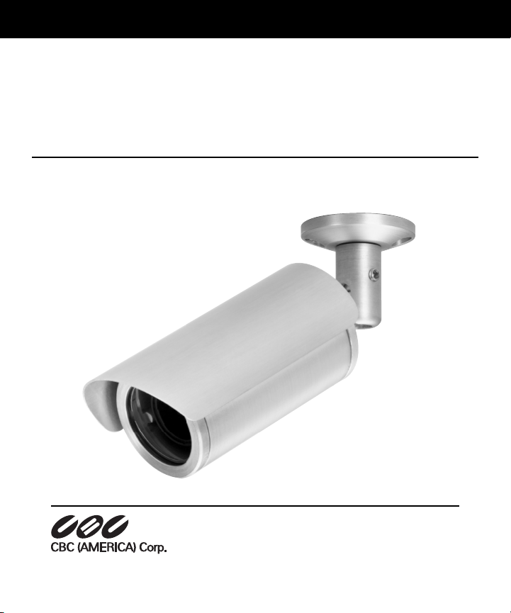
CX Series
Instruction Manual
B/W, Color and Day/Night Outdoor Cameras
www.cbcamerica.com
Please carefully read and observe all instructions
and warnings contained in this manual or on the
product. Improper installation may damage the
device and void the warranty.
Page 2

CX Series Instruction Manual
CONTENTS
BASIC DESCRIPTION . . . . . . . . . . . . . . . . . . . . . . . . . . . . . . . . . . 1
MAJOR FEATURES . . . . . . . . . . . . . . . . . . . . . . . . . . . . . . . . . . . . 1
WIRING CONNECTIONS . . . . . . . . . . . . . . . . . . . . . . . . . . . . . . . 1
MOUNTING THE CAMERA . . . . . . . . . . . . . . . . . . . . . . . . . . . . . . 2
ADJUSTING CAMERA ORIENTATION . . . . . . . . . . . . . . . . . . . . . . 2
LENS ADJUSTMENT . . . . . . . . . . . . . . . . . . . . . . . . . . . . . . . . . . . 2
NOTES . . . . . . . . . . . . . . . . . . . . . . . . . . . . . . . . . . . . . . . . . . . . 3
FCC RULES: PART 15 . . . . . . . . . . . . . . . . . . . . . . . . . . . . . . . . . . 3
DIP Switch Setup: Color Cameras . . . . . . . . . . . . . . . . . . . . . . . . . . 4
DIP Switch Setup: Black and White Cameras . . . . . . . . . . . . . . . . . 5
CAMERA SPECIFICATIONS
CX-NV310A-2 Color/CXH-NV310A-2 Hi-Res Color . . . . . . . . 6
CAMERA SPECIFICATIONS
CX-EV310A-2 B&W Camera . . . . . . . . . . . . . . . . . . . . . . . . . 7
CAMERA SPECIFICATIONS
DXH-NV39A Hi-Res Color Day/Night . . . . . . . . . . . . . . . . . . . 8
MODEL CX-EV310A-2 B/W Camera Components . . . . . . . . . . . . . 9
Page 3

CX Series Instruction Manual
BASIC DESCRIPTION
CX Series cameras utilize a high-sensitivity CCD camera with auto iris varifocal lens in a
compact weatherproof housing. Four versions are available:
1) Model CX-EV310A-2 (B/W with 2.8-10mm auto iris varifocal lens)
2) Model CX-NV310A-2 (Color with 2.8-10mm auto iris varifocal lens)
3) Model CXH-NV310A-2 (Hi-Res Color with 2.8-10mm auto iris varifocal lens)
4) Model DXH-NV39A (Hi-Res Color Day/Night with 3-9mm A/I varifocal lens)
MAJOR FEATURES
• Compact and stylish design for use in commercial or residential applications
• Anodized aluminum weather-proof housing with removable sunshield
• Auto-iris varifocals compensate for changing light conditions and provide maximum
depth of field
• Wide Operating Temperature Range for use in any climate
• Adjustable swivel mount for ceiling or wall installations
• Phase adjustment for synchronizing multiple cameras in 24VAC systems
• 12VDC/24VAC auto-sensing power input
• Optional Day/Night Model with retractable IR cut filter (DXH112-V39A).
WIRING CONNECTIONS
WARNING: Make wiring connections only after it has been determined that power has
been disconnected. Use either a 12VDC regulated power supply (C12DCR-500
recommended) or a 24VAC power supply (C24AC recommended). For 12VDC power
input, determine the polarity prior to connection to the camera. Failure to do so could
lead to permanent damage to the device and void the warranty.
NOTE: A BNC connector (included) can be crimped to the WHITE and GREEN video
signal wires using the supplied butt connectors.
Page 1
Page 4

CX Series Instruction Manual
RED
BLACK
WHITE
GREEN
+12VDC/24VAC
POWER GROUND/24VAC
VIDEO SIGNAL OUT
VIDEO GROUND
MOUNTING THE CAMERA
The camera base has two mounting holes for #8 screws (#8 screws and anchors are
supplied). To mount the camera, loosen the swivel set screw with the 1/8” Allen
wrench (supplied) and mount the base in the desired location. The mounting base
can be removed completely from the bracket if necessary.
ADJUSTING CAMERA ORIENTATION
Loosen the swivel set screw and rear end cap set screw with supplied Allen keys.
Orient the camera and tighten both set screws. Be sure to tighten the rear end cap
set screw to maintain a water-tight seal.
LENS ADJUSTMENT
1) Completely loosen the two Phillips screws on the rear endcap that hold the
housing cover in place, and remove the cover.
2) Loosen the focus and zoom adjustment locking screws.
3) Connect the camera to power and a monitor to adjust focal length and focus
for best image.
4) Tighten focus and zoom locking screws. Recheck image after tightening.
5) Replace cover carefully in order to prevent damage to the camera components.
6) Make sure cover is tight against back plate and tighten two Phillips screws on
housing with equal force.
Page 2
Page 5

CX Series Instruction Manual
NOTES
A) Do not remove desiccant pack! There is a desiccant pack attached to
the housing base under the board camera that is designed to absorb any
moisture trapped inside the housing during adjustment. To avoid excessive
moisture buildup, it is recommended that the camera not be installed in rainy
or excessively damp conditions. It is also advisable to limit the number of times
the housing cover is removed. The desiccant pack can be replaced if
condensation develops inside the housing.
B) If the housing cover is opened frequently or if the gasket dries out, apply a light
coat of good quality silicone-based grease to the gasket to maintain a
watertight seal.
C) Make sure that the end of the cable, including BNC connector and power
connection, are not exposed to the elements. Exposed cable may cause a
power short.
FCC RULES: PART 15
This device can be expected to comply with part 15 of the FCC Rules, provided it is
assembled in exact accordance with the instructions provided with this kit. Operation
is subject to the following conditions: (1) This device may not cause harmful
interference; and (2) this device must accept any interference received including
interference that may cause undesired operation.
Page 3
Page 6

CX Series Instruction Manual
DIP Switch Setup: Color Cameras
IRIS FL BLC SYNC
DC ON ON INT
AES OFF OFF L.L.
123 4
(Factory settings shown. Do not change settings except for BLC function as needed)
1 Iris
2 Flickerless (FL)
Back Light
3
Compensation (BLC)
4 Synchronization Mode
Page 4
DC DC Iris
AES Auto Electronic Shutter
ON Shutter speed to be fixed at 1/100 sec.
OFF Normal position
ON Set to this position when a strong light is in the background
OFF Normal position
INT Internal synchronization mode
LL Line lock mode
Page 7

CX Series Instruction Manual
DIP Switch Setup: Black and White Cameras
IRIS AGC BLC SYNC
DC OFF ON INT
AES ON OFF L.L.
123 4
(Factory settings shown. Do not change settings except for BLC function as needed)
1 Iris
Auto Gain Control
2
3
4 Synchronization Mode
(AGC)
Back Light
Compensation (BLC)
DC DC Iris
AES Auto Electronic Shutter
ON Gain level to be fixed at min.
OFF Set to this position to improve camera sensitivity in low light conditions
ON Set to this position when a strong light is in the background
OFF Normal position
INT Internal synchronization mode
LL Line lock mode
Page 5
Page 8

CX Series Instruction Manual
CAMERA SPECIFICATIONS
CX-NV310A-2 Color/CXH-NV310A-2 Hi-Res Color
Video Signal System NTSC Standard
Image Output 1 Volt p-p/75 Ohms
Scanning System 2:1 Interlace
Resolution 330 lines horz (standard)/480 lines horz (hi-res)
Sensitivity @f1.2 1.0 lux (50 IRE) / 1.5 lux (50 IRE)
S/N Ratio More than 50dB
Image Sensor 1/4" Interline Transfer CCD
Effective Picture Elements 510(H) x 492(V) / 768(H) x 492(V)
Scanning Frequency Horz. 15.734KHz/Vert 59.9Hz
Sync System Internal / Line Lock
Gamma 0.45
Gain Control Automatic
Iris DC Auto Iris
Power Source DC 12V ±1.0 volt or 24VAC
Power Consumption min 200 mA
Operating Temperature Range -30ºF to +140º F
Lens 2.8 ~ 10mm f1.2 Auto Iris
0.4 lux (30 IRE) / 0.7 lux (30 IRE)
Page 6
Page 9

CX Series Instruction Manual
CAMERA SPECIFICATIONS
CX-EV310A-2 B&W Camera
Video Signal System EIA Standard
Image Output 1 Volt p-p/75 Ohms
Scanning System 2:1 Interlace
Resolution 380 lines horz
Sensitivity @f1.2 0.1 lux (50 IRE)
S/N Ratio 50dB (AGC off)
Image Sensor 1/4" Interline Transfer CCD
Pixel Size 9.60 um(H) x 7.50 um(V)
Effective Picture Elements 510(H) x 492(V)
Scanning Frequency Horz. 15.734KHz/Vert 59.9Hz
Sync System Internal / Line Lock
Gamma 0.45
AGC +12dB
Iris DC Auto Iris
Power Source DC 12V ± 1.0 volt or 24VAC
Power Consumption min 200 mA
Operating Temperature Range -30ºF to +140º F
Lens 2.8 ~ 10mm f1.2 Auto Iris
0.04 lux (30 IRE)
Page 7
Page 10

CX Series Instruction Manual
CAMERA SPECIFICATIONS
DXH-NV39A Hi-Res Color Day/Night
Video Signal System NTSC Standard
Image Output 1 Volt p-p/75 Ohms
Scanning System 2:1 Interlace
Resolution 480 lines horz
Sensitivity @f1.4 0.21 lux (50 IRE-Night Mode/B/W)
S/N Ratio More than 50dB
Image Sensor 1/4" Interline Transfer CCD
Effective Picture Elements 768(H) x 494(V)
Scanning Frequency Horz. 15.734KHz/Vert 59.9Hz
Sync System Internal / Line Lock
Gamma 0.45
Gain Control Automatic
Iris DC Auto Iris
Power Source DC 12V ± 1.0 volt or 24VAC
Power Consumption 300 mA recommended
Operating Temperature Range -30ºF to +140º F
Lens 3-9mm f1.4 Auto Iris Day/Night Lens with ED glass
0.07 lux (30 IRE-Night Mode/B/W)
and filter removal mechanism
Page 8
Page 11

CX Series Instruction Manual
MODEL CX-EV310A-2 B/W Camera Components
Mounting Base Removable Sunshield
Swivel Set
Screw
Removable
Front
Window
Swivel
Pedestal
Philips Screws
(Secure Housing
Cover to End Cap)
Rear End Cap Set Screw
Line Phase
Adjustment
Dip Switch Adjustments
Housing
Feed-Thru
Bracket
Zoom
Adjustment Ring
Zoom Lock Screw
Cover
Focus
Adjustment
Ring
Focus
Lock Screw
Page 9
Page 12

TOKYO, JAPAN COMMACK, NEW YORK TORRANCE, CALIFORNIA
2005 CBC (AMERICA) CORP. All Rights Reserved. 11/05
©
NEW YORK: 55 MALL DRIVE • COMMACK, NY 11725
TEL 1-800-422-6707 • 631-864-9700 • FAX 631-543-5426
CALIFORNIA: 20521 EARL ST. • TORRANCE, CA 90503
TEL 1-800-888-0131 • 310-793-1500 • FAX 310-793-1506
www.cbcamerica.com
TOKYO HEADQUARTERS:
• TOKYO 104, JAPAN • TEL 03 536-4500 • FAX 03 536-4780
2-15-13, TSUKISHIMA, CHUO-KU
 Loading...