

Page 1
TIME LAPSE VCR
OWNER’S MANUAL
MODEL: CTR-030NC-2
Before connecting, operating, or adjusting this
product, please read this instruction booklet
carefully and completely.
POWER
V-POS
ON OFF
H-POS
TIMER
REC/PLAY HOURS
CURSOR
MENU
ENTER
TRACKING
SHARPNESS
LOCK
HARD
SOFT
TIME/CNT/REM
ALARM/INDEX
COUNTER
CLEAR
Page 2

Page 3

IMPORTANT SAFETY INSTRUCTIONS
CAUTION:
PLEASE READ AND OBSERVE ALL WARNINGS AND INSTRUCTIONS IN THIS OWNER’S MANUAL. AND THOSE MARKED ON THE PRODUCT. RETAIN THIS BOOKLET FOR FUTURE REFERENCE.
This product has been designed and manufactured to assure personal safety. Improper use can result in electric
shock or fire hazard. The safeguards incorporated in this product will protect you if you observe the following procedures for installation, use, and servicing.
This product does not contain any parts that can be repaired by the user.
DO NOT REMOVE THE CABINET COVER, OR YOU MAY BE EXPOSED TO DANGEROUS VOLTAGE. REFER
SERVICING TO QUALIFIED SERVICE PERSONNEL ONLY.
1. Read these instructions. - All these safety and oper-
ating instructions should be read before the product is
operated.
2. Keep these instructions. - The safety, operating and
use instructions should be retained for future reference.
3. Heed all warnings. - All warnings on the product and
in the operating instructions should be adhered to.
4. Follow all instructions. - All operating and use
instructions should be followed.
5. Do not use this product near water. – For example:
near a bath tub, wash bowl, kitchen sink, laundry tub,
in a wet basement; or near a swimming pool; and
other areas located near water.
6. Clean only with dry cloth. – Unplug this product
from the wall outlet before cleaning. Do not use liquid
cleaners.
7.
Do not block any ventilation openings. Install in
accordance with the manufacturer’s instructions. -
Slots and openings in the cabinet are provided for
ventilation and to ensure reliable operation of the
product and to protect it from over- heating. The
openings should never be blocked by placing the
product on a bed, sofa, rug or other similar surface.
This product should not be placed in a built-in installation such as a bookcase or rack unless proper ventilation is provided or the manufacturer’s instructions
have been adhered to.
8. Do not install near any heat sources such as radiators, heat registers, stoves, or other apparatus
(including amplifiers) that produce heat.
9. D
o not defeat the safety purpose of the polarized
or grounding-type plug. A polarized plug has two
blades with one wider than the other. A grounding
type plug has two blades and a third grounding
prong. The wide blade or the third prong are provided for your safety. If the provided plug does not
fit into your outlet, consult an electrician for
replacement of the obsolete outlet.
10. Protect the power cord from being walked on or
pinched particularly at plugs, convenience
receptacles, and the point where they exit from
the product.
11. Only use attachments/accessories specified by
the manufacturer.
12. Use only with the cart, stand, tripod, bracket, or
table specified by the manufacturer, or sold with
apparatus. When a cart is used, use caution
when moving the cart/product combination to
avoid injury from tip-over.
13. Unplug this product during lightning storms or
when unused for long periods of time.
14.
Refer all servicing to qualified service personnel.
Servicing is required when the product has
been damaged in any way, such as power-supply cord or plug is damaged, liquid has been
spilled or objects have fallen into the product,
the product has been exposed to rain or moisture, does not operate normally, or has been
dropped.
Page 4
2
INTRODUCTION
WARNING : TO REDUCE THE RISK OF FIRE OR ELECTRIC SHOCK,
DO NOT EXPOSE THIS PRODUCT TO RAIN OR MOISTURE.
RISK OF ELECTRIC SHOCK
DO NOT OPEN
CAUTION
CAUTION : TO REDUCE THE RISK
OF ELECTRIC SHOCK,
DO NOT REMOVE COVER (OR BACK);
NO USER-SERVICEABLE PARTS INSIDE
REFER SERVICING TO QUALIFIED SERVICE
PERSONNEL.
CAUTION : TO PREVENT ELECTRIC SHOCK,
DO NOT USE THIS PLUG WITH AN EXTENSION CORD, RECEPTACLE OR OTHER OUTLET UNLESS THE PLUG CAN BE FULLY
INSERTED WITHOUT EXPOSING ANY PARTS
OF THE BLADES.
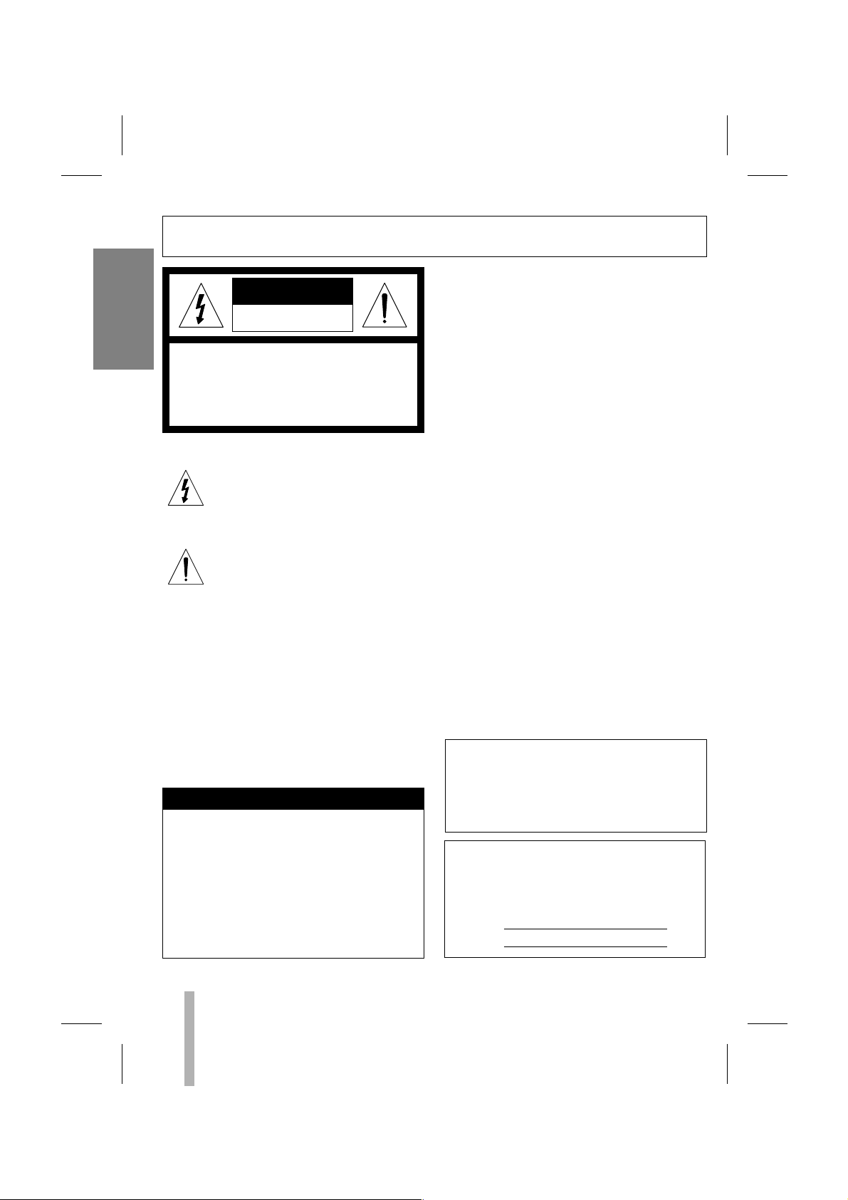
This lightning flash with arrowhead symbol within an equilateral triangle is intended to alert the user to the presence of
uninsulated dangerous voltage within the
product’s enclosure that may be of sufficient magnitude to constitute a risk of
electric shock to persons.
The exclamation point within an equilateral triangle is intended to alert the user to
the presence of important operating and
maintenance (servicing) instructions in the
literature accompanying the product.
WARNING: Do not install this equipment in a confined space such as a bookcase or similar unit.
CAUTION: The apparatus should not be exposed
to water (dripping or splashing) and no objects
filled with liquids, such as vases, should be placed
on the apparatus.
IMPORTANT COPYRIGHT INFORMATION: Many
television programs and films are copyrighted.
In certain circumstances, copyright law may apply
to private in-home video taping of copyrighted
materials.
If you pour a cold liquid into a glass, water vapor
in the air will condense on the surface of the
glass. This is moisture condensation. Moisture
condensation on the head drum, one of the most
crucial parts of the unit, will cause damage to the
tape.
When the VCR is exposed to a rapid temperature
change from cold to warm, some condensation
will occur. Under this condition, connect the power
cord to the AC line, press POWER button on and
allow at least two hours for the VCR to dry out.
MOISTURE CONDENSATION
The serial number is found on the back of this
unit. This number is unique to this unit and not
available to others. You should record requested
information here and retain this guide as a permanent record of your purchase.
Model No.
Serial No.
FCC WARNING: This equipment may generate or
use radio frequency energy. Changes or modifications to this equipment may cause harmful interference unless the modifications are expressly
approved in the instruction manual. The user could
lose the authority to operate this equipment if an
unauthorized change or modification is made.
REGULATORY INFORMATION: FCC Part 15
This product has been tested and found to comply
with the limits for a Class A digital device, pursuant to Part 15 of the FCC Rules. These limits
are designed to provide reasonable protection
against harmful interference when the product is
operated in a residential installation. This product
generates, uses, and can radiate radio frequency
energy and, if not installed and used in accordance with the instruction manual, may cause
harmful interference to radio communications.
However, there is no guarantee that interference
will not occur in a particular installation. If this
product does cause harmful interference to radio
or television reception, which can be determined
by turning the product off and on, the user is
encouraged to try to correct the interference by
one or more of the following measures:
Reorient or relocate the receiving antenna.
Increase the separation between the product
and receiver.
Connect the product into an outlet on a circuit
different from that to which the receiver is
connected.
Consult the dealer or an experienced
radio/TV technician for help.
In case of using with a portable radio closely, the VCR may not operate normally.
Page 5

3
CONTENTSFEATURES
INTRODUCTION
Features/Contents . . . . . . . . . . . . . . . . . . . . . . . . . . . .3
PREPARATION
Control Names and Locations . . . . . . . . . . . . . . . . .4-6
Installation/VCR to Monitor and CCD Camera
Connection . . . . . . . . . . . . . . . . . . . . . . . . . . . . . . . . .7
Multiplexer/Matrix Switcher Connections . . . . . . . . . .8-9
Alarm Record Connection . . . . . . . . . . . . . . . . . . . . .10
Series Record Connection . . . . . . . . . . . . . . . . . . . . .10
Setting the On Screen Display . . . . . . . . . . . . . . . . . .11
Setting the Setup Menu . . . . . . . . . . . . . . . . . . . . . . .12
Setting the Set Time . . . . . . . . . . . . . . . . . . . . . . . . .13
Video Cassette Tapes . . . . . . . . . . . . . . . . . . . . . . . .14
PLAYBACK
Normal Playback . . . . . . . . . . . . . . . . . . . . . . . . . . . .15
Special Effects Playback . . . . . . . . . . . . . . . . . . .16-17
Tape Counter Memory Feature . . . . . . . . . . . . . . . . .18
RECORDING
Normal Recording . . . . . . . . . . . . . . . . . . . . . . . . . . .19
Repeat Recording . . . . . . . . . . . . . . . . . . . . . . . . . . .20
Timer Recording . . . . . . . . . . . . . . . . . . . . . . . . . . . .21
Series Recording . . . . . . . . . . . . . . . . . . . . . . . . . . .22
Alarm Recording . . . . . . . . . . . . . . . . . . . . . . . . .23-24
ADDITIONAL INFORMATION
Check the Alarm Record Information . . . . . . . . . . . . .25
Recording Time Table Information . . . . . . . . . . . . . . .25
Check the Power Fail Recall . . . . . . . . . . . . . . . . . . .26
Use to Lock On/Off Switch . . . . . . . . . . . . . . . . . . . .26
Self-Diagnosis . . . . . . . . . . . . . . . . . . . . . . . . . . . . . .27
Service Guide Table . . . . . . . . . . . . . . . . . . . . . . . . .28
VIDEO Head Cleaning . . . . . . . . . . . . . . . . . . . . . . .28
Troubleshooting . . . . . . . . . . . . . . . . . . . . . . . . . . . .29
Specifications . . . . . . . . . . . . . . . . . . . . . . . . . . . . . .30
•Time Lapse VCR Function
•Trigger Function
• Buzzer Function
• Auto Switcher Functionality
•Tape Compatibility
• Elapsed Time Display
• Series Recording Function
•Alarm Recording Function
Warning : The battery used in this device may present a fire or chemical burn hazard if mis-
treated. Do not recharge, disassemble, incinerate, or heat above 212°F (100°C). Replace the
battery with Matsushita Elec. Ind., Co., Ltd. (Panasonic) part no. VL2330 only. Use of another
battery may present a risk of fire or explosion. Dispose of used batteries. Keep away from
children. Do not disassemble or dispose of in fire.
INTRODUCTION
Page 6

CONTROL NAMES AND LOCATIONS
4
PREPARATION
FRONT
1. TIME/CNT/REM BUTTON
To switch among the clock, tape counter
and tape remaining time.
2. POWER BUTTON
To turn the VCR on and off.
3. TIMER BUTTON
To set timer recording.
4. REC/PLAY HOURS BUTTON
To change the Play or Record speed to a
lower or higher value.
5. V-POS BUTTON
To move the position of the Time/Date
display in the vertical direction.
6. H-POS BUTTON
To move the position of the Time/Date
display in the horizontal direction.
7. MENU BUTTON
Displays the programming menu on the
monitor or TV screen.
8. CURSOR (UP/DOWN) BUTTONS
To select the item on the menu.
9. CASSETTE COMPARTMENT
Where the video cassette is inserted.
10. STOP BUTTON
To stop the tape.
11. PLAY/REC CHECK BUTTON
To playback a recorded tape and used
for the Record Check function.
12. P/STILL(PAUSE STILL) BUTTON
To still playback or to pause recording.
13. SHUTTLE RING
To fast forward or rewind the tape.
14. JOG DIAL
Rotate to advance or reverse advance
video picture while viewing a still
picture.
15. RECORD BUTTON
To record Video.
16. EJECT BUTTON
To eject a stopped cassette.
17. VCR FUNCTION INDICATOR PANEL
Details are on page 6.
18. ENTER BUTTON
To select items on the menu screen.
19. SHARPNESS CONTROL
To adjust the playback quality.
20. TRACKING (
EE/DD
) BUTTON
To adjust the manual tracking.
21. LOCK ON/OFF SWITCH
To switch lock and unlock.
22. COUNTER CLEAR BUTTON
To set the counter to zero or erase the
information on the menu screen.
23. ALARM INDEX
To active and deactivate (toggle) the
alarm index function.
12 3 4 5 6 7 8 9 10 11 12 13
23 22 21 20 19 18 17 16 15 14
POWER
TIME/CNT/REM
ALARM/INDEX
COUNTER
CLEAR
LOCK
ON OFF
TIMER
CURSOR
TRACKING
V-POS
REC/PLAY HOURS
SHARPNESS
SOFT
H-POS
MENU
ENTER
HARD
Page 7
5
PREPARATION
CONTROL NAMES AND LOCATIONS (cont’d)
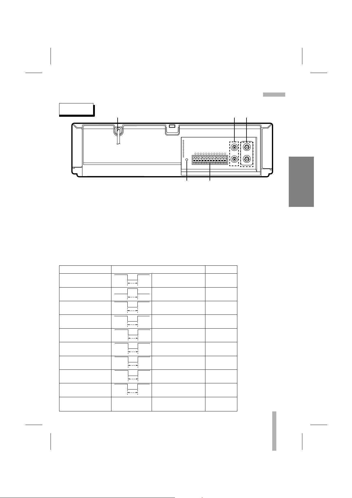
1. POWER CORD
Connect only to an AC 100-240V, 50/60Hz
outlet.
2. AUDIO IN/OUT JACK
Connect the audio input and output
terminal.
3. VIDEO IN/OUT JACK
Connect the video input and output
terminal.
4. RESET BUTTON
Use this button to reset the VCR.
5. 12-PIN TERMINAL BLOCK
Connect external signals.
VIDEO IN
AUDIO IN
AUDIO OUT
VIDEO OUT
1 2 3 456 7 8 9 10 11 12
RESET
1
ALARM IN
2
ALARM OUT
3
ALARM RESET
4
GND
5
SERIES IN
6
SERIES OUT
7
WARNING OUT
8
TRIGGER OUT
9
GND
10
LOW TAPE OUT
11
1 SHOT REC IN
12
GND
REAR
1
2
3
4
5
TERMINAL SIGNAL LEVEL IN/OUT
1. ALARM IN INPUT
2. ALARM OUT OUTPUT
3. ALARM RESET INPUT
5. SERIES IN INPUT
6. SERIES OUT OUTPUT
7. WARNING OUT OUTPUT
8. TRIGGER OUT OUTPUT
10. LOW TAPE OUT OUTPUT
11. 1-SHOT REC IN INPUT
4, 9, 12. GND COMMON
VIH
VIL
T
VOH
VOL
T
VIH
VIL
T
VIH
VIL
T
VOH
VOL
T
VOH
VOL
T
VOH
VOL
T
VOH
VOL
T
VIH
VIL
T
Terminal Signal Levels
VIH: 4~5V, VIL: 0~0.6V
T: above 250msec
VOH: 4~5V, VOL: 0~0.6V
T: ALARM REC STATE
VIH: 4~5V, VIL: 0~0.6V
T: above 250msec
VIH: 4~5V, VIL: 0~0.6V
T: above 250msec
VOH: 4~5V, VOL: 0~0.6V
T: above 250msec
VOH: 4~5V, VOL: 0~0.6V
T: until any key is pressed
VOH: 4~5V, VOL: 0~0.6V
T: above 8~10msec
VOH: 4~5V, VOL: 0~0.6V
T: below 5 min, end of tape
VIH: 4~5V, VIL: 0~0.6V
T: above 250msec
0V
–
Page 8
6
PREPARATION
ALARMHSERIES TIMER
INDEX
P. FAIL
K.LOCK
REPEAT
REC
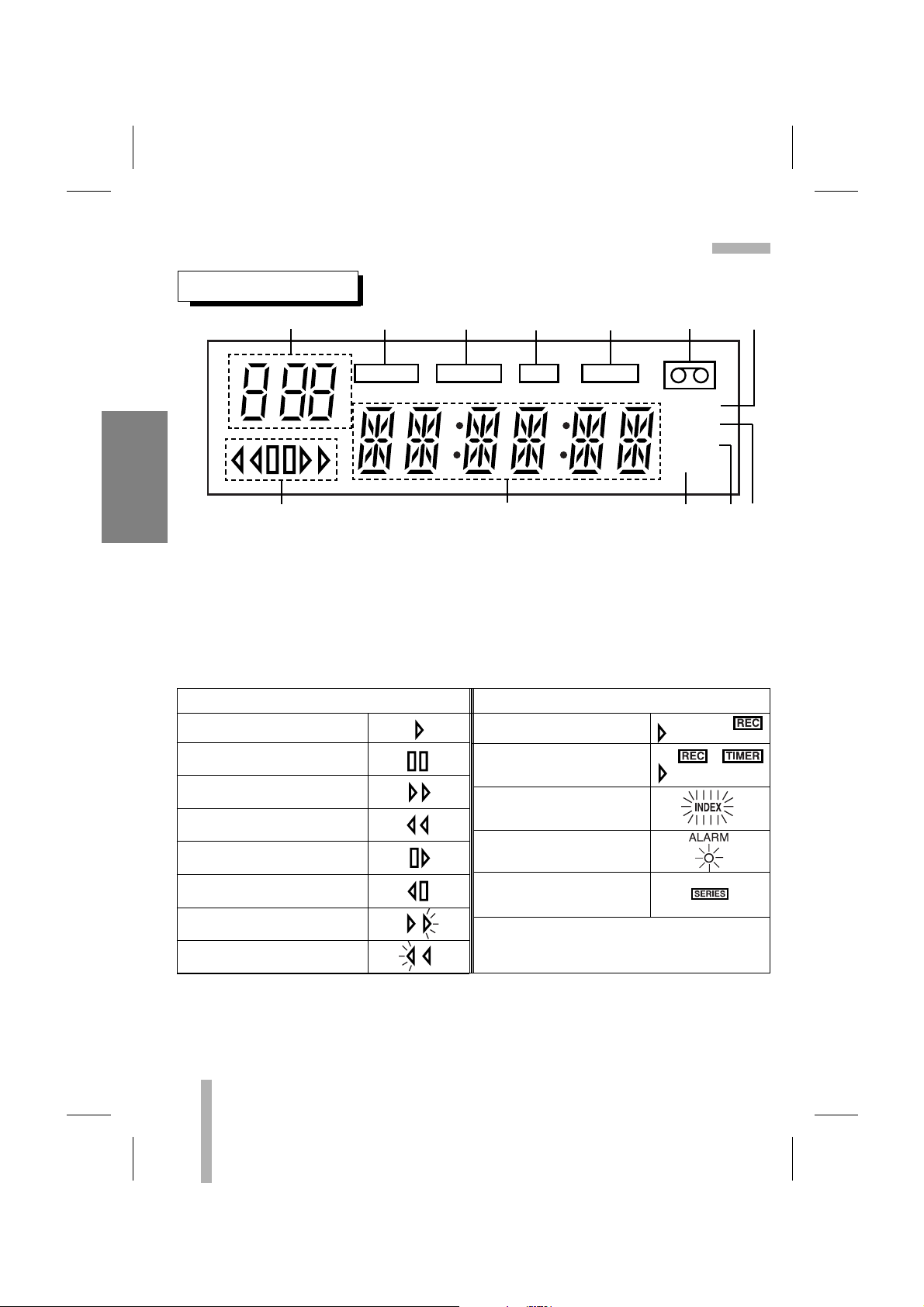
INDICATOR PANEL
1. TIME LAPSE VCR TIME Indication
2. ALARM Indication
(ALARM REC ON indication)
3. SERIES Indication
4. RECORD Indication
5. TIMER Indication
6. CASSETTE Indication
7. INDEX Indication
8. POWER FAILURE Indication
9. KEY LOCK indication
10. REPEAT Indication
11.FUNCTION Indication
(CLOCK, TAPE COUNTER, ERROR)
12. VCR FUNCTION Indication
VCR FUNCTION Indication
PLAYBACK INDICATION RECORDING INDICATION
PLAYBACK
PAUSE STILL
FAST FORWARD
REWIND
CUE
REVIEW
RECORDING
TIMER RECORDING
ALARM INDEX
ALARM RECORDING
SERIES RECORDING
FORWARD SLOW PICTURE/
FORWARD FIELD ADVANCE
REVERSE SLOW PICTURE/
REVERSE FIELD ADVANCE
CONTROL NAMES AND LOCATIONS (cont’d)
1234567
12 11 10 9 8
Page 9
7
PREPARATION
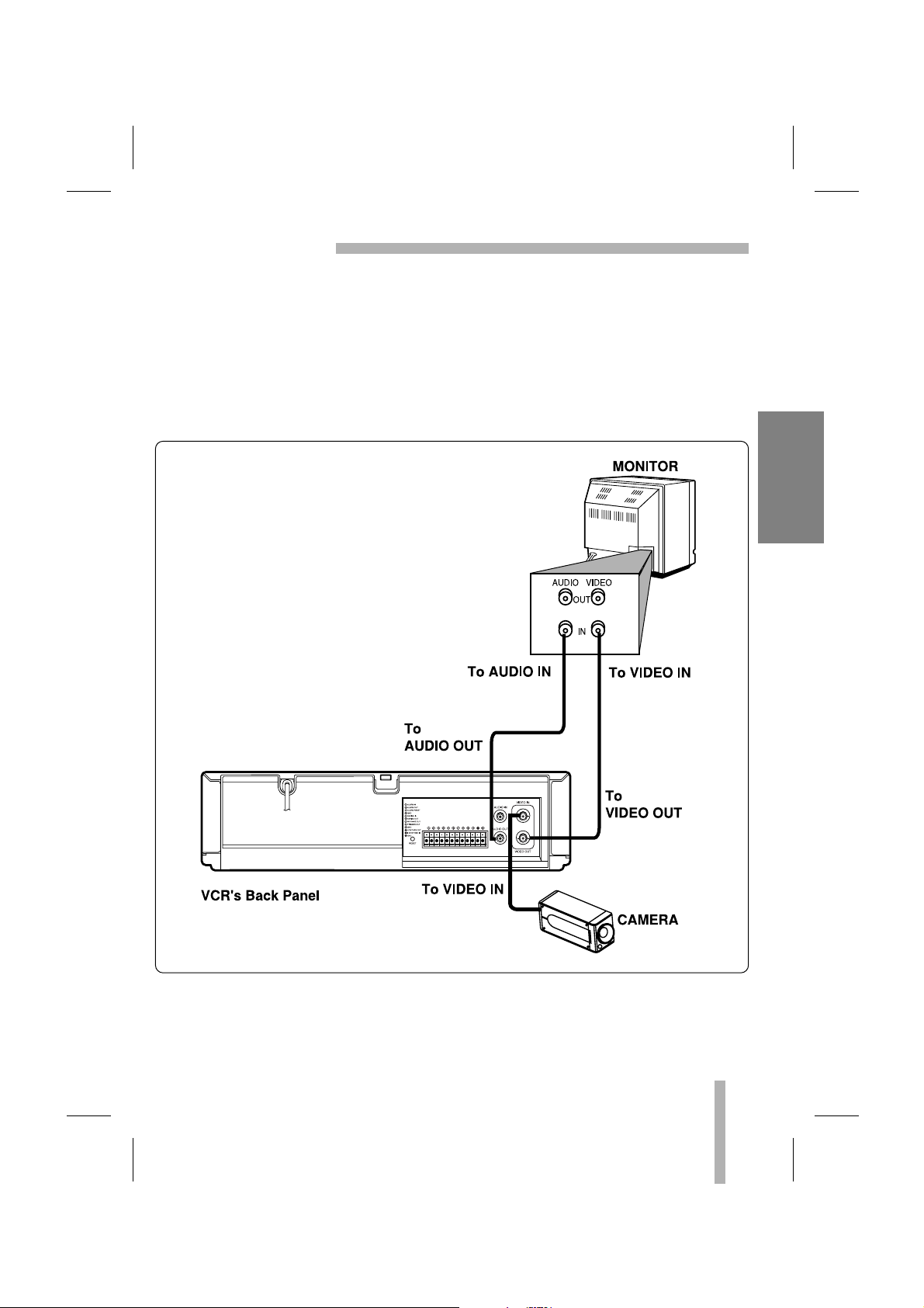
INSTALLATION
VCR TO MONITOR AND CCD CAMERA CONNECTION
•
Connect your VCR’s AUDIO/VIDEO output jacks to the A/V input jacks on back of your
monitor.
If your monitor does not have A/V input jacks, exchange the monitor or TV for one with A/V
input jacks.
• Connect the CCD camera to VCR’s VIDEO input jack.
• The cables for audio and video connection are not provided with your VCR.
Page 10
8
PREPARATION
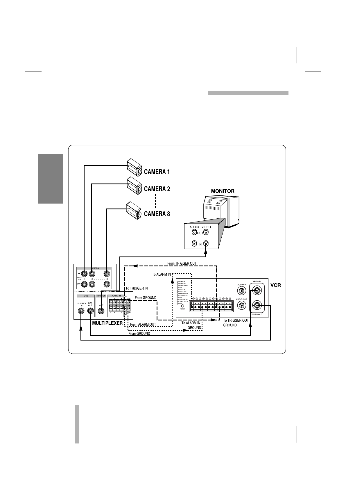
MULTIPLEXER CONNECTIONS
HOW TO CONNECT MULTIPLEXER WITH TRIGGER INPUT TERMINAL
If the multiplexer has two output terminals (monitor OUT, PB OUT), connect monitor to the PB
OUT terminal if you want to see the playback picture.
To use the multiplexer and trigger function properly, refer to the multiplexer instruction manual.
Page 11

9
PREPARATION
MATRIX SWITCHER CONNECTIONS
HOW TO CONNECT SWITCHER WITHOUT TRIGGER INPUT TERMINAL
Page 12

10
PREPARATION
SERIES RECORD CONNECTION
1 2 3 456 7 8 9 10 11 12
ALARM RECORD CONNECTION
Connect alarm output of external device to alarm input of VCR, and then connect alarm out
GND of device to alarm input GND of VCR.
Make all connections to the first VCR before making any connections to the other VCRs in the
series.
After connecting, turn on the VCRs and then select the ON: SERIES mode in REC MODE
menu. (Refer to the page 22.)
Page 13

11
SETTING THE ON SCREEN DISPLAY
MENU
VCR SET UP
REC MODE SET UP
TIMER REC SET UP
ALARM SET UP
POWER FAIL RECALL
LANGUAGE ENGLISH
(UP) (DOWN) (ENTER) (MENU)
The following pages describe the on screen selections to be set.
PREPARATION
•Turn on the power of both the VCR and the monitor.
• If you have a TV instead of monitor, turn on the power of TV
and then set the TV’s source selector to VIDEO.
Your VCR allows adjustment of several features.
MENU SELECTION
MAIN MENU
1 Press MENU button and the main menu will appear.
2 Select the desired menu with the UP or DOWN button and
then press the ENTER button.
VCR SET UP
CLOCK SET
ELAPSED TIME
VHS-TAPE T-120
VIDEO AUTO
DISPLAY ON
AUDIO PLAY ON
QUASI V-SYNC ON
(UP) (DOWN) (ENTER) (MENU)
REC MODE
REC TIME 000H
INTERVAL 10SEC
TRIGGER OUT 1 FIELD
SERIES OFF
REPEAT OPTION :
STOP AT EOT.
(UP) (DOWN) (ENTER) (MENU)
ALARM SET UP
REC MODE L6H
DURATION 1 MIN
BUZZER ON
ALARM READY ON
ALARM RECALL
(UP) (DOWN) (ENTER) (MENU)
POWER FAIL RECALL
1 OFF 01/01/03 20:56:55
ON 01/01/03 20:56:57
2 OFF 01/01/03 20:56:50
ON 01/01/03 20:56:53
3 OFF 01/01/03 20:56:47
ON 01/01/03 20:56:49
4 OFF 01/01/03 20:56:43
ON 01/01/03 20:56:46
(DOWN) (CLEAR) (MENU)
SET DAY START END SPD
OFF - - - - - : - - - - : - - L6
OFF - - - - - : - - - - : - - L6
OFF - - - - - : - - - - : - - L6
OFF - - - - - : - - - - : - - L6
OFF - - - - - : - - - - : - - L6
OFF - - - - - : - - - - : - - L6
OFF - - - - - : - - - - : - - L6
OFF - - - - - : - - - - : - - L6
(UP) (DOWN) (ENTER) (CLEAR)
VCR SET UP (page 12)
REC MODE (pages 19-20, 22)
TIMER REC SET UP (page 21)
ALARM SET UP (pages 23-25)
POWER FAIL RECALL (page 26)
MENU
VCR SET UP
REC MODE SET UP
TIMER REC SET UP
ALARM SET UP
POWER FAIL RECALL
LANGUAGE ENGLISH
(UP) (DOWN) (ENTER) (MENU)
LANGUAGE SELECTION
You can select the
language among
ENGLISH, FRANCAIS,
DEUTSCH, ITALIANO,
ESPAÑOL, POLSKI and
.
PREPARATION
Page 14

12
PREPARATION
SETTING THE SETUP MENU
6. AUDIO PLAY
5. DISPLAY
3. VHS-TAPE
2. ELAPSED TIME
1. CLOCK SET
MAIN MENU
SETUP MENU
Press UP or DOWN to
choose a desired item on
the SETUP menu.
Choose the camera’s color type (B/W, AUTO, COLOR) by
pressing
ENTER
.
The time/date DISPLAY is switched between ON and OFF by
pressing ENTER.
The audio is switched between ON and OFF during playback
by pressing ENTER.
Details are on page 13.
Check the used time of head by pressing
ENTER
.
Choose the tape type used (T-120, T-160, T-180, T-210) by
pressing ENTER.
Recording time mode on OSD & FLD is changed by selecting
the tape type.
Refer to the left recording time table. (*L : Linear Mode)
The selection of tape is supposed to ‘T-120’ on this manual.
PREPARATION
•Turn on the power of both the VCR and the monitor.
• If you have a TV instead of monitor, turn on the power of TV
and then set the TV’s source selector to VIDEO.
1 Press MENU button. The main menu will appear.
Press DOWN or UP to choose VCR SET UP.
2 Press ENTER button. The VCR SET UP menu will appear.
VCR SET UP
CLOCK SET
ELAPSED TIME
VHS-TAPE T-120
VIDEO AUTO
DISPLAY ON
AUDIO PLAY ON
QUASI V-SYNC ON
(UP) (DOWN) (ENTER) (MENU)
VCR SET UP
CLOCK SET
ELAPSED TIME
VHS-TAPE T-120
VIDEO AUTO
DISPLAY ON
AUDIO PLAY ON
QUASI V-SYNC ON
(UP) (DOWN) (ENTER) (MENU)
ELAPSED TIME
DATE OF FIRST USE:
01/01/03
PERIOD IN USE:
00004 HOURS
(MENU)
MENU
VCR SET UP
REC MODE SET UP
TIMER REC SET UP
ALARM SET UP
POWER FAIL RECALL
LANGUAGE ENGLISH
(UP) (DOWN) (ENTER) (MENU)
7. QUASI-SYNC
The quasi-sync is switched between ON and OFF during playback by pressing ENTER.
T-120 T-160 T-180 T-210
L6H L8H L9H L10H
L18H L24H L27H L31H
L30H L40H L45H L52H
72H 104H 117H 136H
96H 136H 153H 178H
120H 168H 189H 220H
168H 232H 261H 304H
240H 328H 349H 430H
480H 648H 729H 850H
960H 1288H 1449H 1690H
000H 000H 000H 000H
Recording Time Table
tape type
Recording
time mode
displayed on
OSD & FLD
4. VIDEO
Page 15

13
PREPARATION
SETTING THE SET TIME
PREPARATION
•Turn on the power of both the VCR and the monitor.
• If you have a TV instead of monitor, turn on the power of TV
and then set the TV’s source selector to VIDEO.
Example: May 23, 2003 ; 17:30
The day of the week will display automatically.
• The clock uses the 24-hour system.
• The initial SET DAY Setting is JANUARY 1, 2003.
MAIN MENU
VCR SET UP MENU
CLOCK SET UP MENU
1 Press MENU button. The main menu will appear.
2 Press DOWN or UP to select the SET UP item and then
press ENTER. The SET UP menu will appear.
3 Press
DOWN or UP
to select the CLOCK SET item and then
press ENTER. The CLOCK SET UP menu will appear.
4 Press ENTER and then DOWN or UP to set a month and
then press ENTER to move to day item.
5
Repeat step 4 to select
the day, year and time.
6 Press MENU button when finished.
Things to know before starting
L12H
17: 30 : 00
05 / 23 / 03
VCR SET UP
CLOCK SET
ELAPSED TIME
VHS-TAPE T-120
VIDEO AUTO
DISPLAY ON
AUDIO PLAY ON
QUASI-V-SYNC ON
(UP) (DOWN) (ENTER) (MENU)
CLOCK SET UP
MM/DD//YY
DATE 05 / 23 / 03 FRI
HH/MM/SS
TIME 17 / 30 / 00
(UP) (DOWN) (ENTER) (MENU)
MENU
VCR SET UP
REC MODE SET UP
TIMER REC SET UP
ALARM SET UP
POWER FAIL RECALL
LANGUAGE ENGLISH
(UP) (DOWN) (ENTER) (MENU)
(TV screen/monitor)
Page 16

14
PREPARATION
VIDEO CASSETTE TAPES
• Do not expose video cassettes to extreme heat, high humidity, or strong magnetic fields.
• Do not tamper with the cassette mechanism.
• Do not touch the tape with your fingers.
• Always store an unused cassette in its case.
Hold the cassette with the arrow side up (top). Insert the
cassette gently into the slot in the direction of the arrow (on the
cassette) until the loading mechanism automatically pulls the
cassette into the unit. Make certain that the cassette is inserted
correctly.
• If the cassette is not loaded correctly, the VCR will eject the
cassette automatically after approximately 3 seconds.
Press the STOP/EJECT button twice. The cassette will be ejected automatically. After the cassette is visible in the tape slot, pull
it out to remove it.
• Unloading the cassette is possible only when the power cord
is connected to the wall outlet.
• The cassette can be ejected when the STOP/EJECT button is
pressed, even if the VCR’s power is OFF.
UNLOADING
LOADING
WHEN HANDLING VIDEO CASSETTES
To prevent accidental erasure, remove the tab after
recording.
To record again, cover the
hole with vinyl tape.
SAFETY TAB
Page 17

15
NORMAL PLAYBACK
PLAYBACK
The indicator will light and the VCR will power-up automatically.
• If a tape without a record protect tab is inserted, the unit will
start the playback automatically.
Press REC/PLAY HOURS
EE
or DDbutton to choose the desired
time mode.
The selected time is displayed in the VCR indicator panel.
Select the time while the tape is stopped or being played back.
L6H ➔L18H ➔L30H ➔72H➔96H ➔120H ➔168H ➔240H➔ 480H➔ 960H
• The time mode can not be changed while the tape is playing
back in L2H and L4H.
• If the tape reaches the end before STOP is pressed, the VCR
will automatically stop and rewind.
If noise appears on the screen during playback, press either
TRACKING (
DD/EE
) buttons until the noise on the screen is
reduced.
• In case of vertical jitter, adjust these controls very carefully.
•Tracking is automatically reset to normal when the tape is
ejected.
TRACKING CONTROL
NORMAL PLAYBACK
1 Insert a prerecorded video cassette.
2 Press the PLAY button.
3 Press the STOP button to stop playback.
PREPARATION
•Turn on the power of both the VCR and the monitor.
• If you have a TV instead of monitor, turn on the power of TV
and then set the TV’s source selector to VIDEO.
NOTES:
•Apicture may vibrate vertically, but this is normal.
•Adistortion may appear on the top of the screen, but this is normal.
•Asound may be muted during playback, but this is normal.
• If the recording hour and playback hour are different, the sound may not play back normally.
(Set the AUDIO PLAY on the SETUP menu to OFF mode.)
POWER
V-POS
H-POS
TIME/CNT/REM
TIMER
REC/PLAY HOURS
CURSOR
ALARM/INDEX
MENU
COUNTER
TRACKING
ENTER
CLEAR
SHARPNESS
LOCK
HARD
SOFT
ON OFF
REC/PLAY HOURS
TRACKING
Page 18

16
SPECIAL EFFECTS PLAYBACK
PLAYBACK
During PLAYBACK mode...
Still picture will appear on the monitor.
• If a still picture vibrates vertically, stabilize it by pressing the
TRACKING(
▼/▲) buttons.
• If the VCR is left in the STILL mode for more than 5 minutes,
the VCR will automatically enter the STOP mode to protect the
tape and video heads.
During PLAYBACK mode...
The picture will slowly advance to forward or reverse field by
field.
During STOP mode...
The INDEX indicator will appear in the VCR indicator panel.
Alarm video will play for 5 seconds and then search to the next
alarm recording.
1 Press the P/STILL button.
2 To continue normal playback, press the PLAY button.
TO WATCH A STILL PICTURE
TO WATCH A FIELD ADVANCE PICTURE
1 Press the P/STILL button.
2 Rotate the JOG dial to forward or reverse.
3 To continue normal playback, press the PLAY button.
1 Press the ALARM INDEX button.
2 Rotate the SHUTTLE ring to forward or reverse.
TO SEARCH ALARM RECORDING
ALARM/INDEX
REC
TRACKING
Page 19

17
PLAYBACK
SPECIAL EFFECTS PLAYBACK (cont’d)
NOTES:
• Horizontal lines (noise bars) will appear on the monitor screen, but this is normal.
• The audio is automatically muted during special effect modes, so there is no sound during search.
• During the high-speed picture search modes, a short period is needed to stabilize tape speed when reentering the PLAY mode. Slight interference may be observed during this period.
During Still mode...
Rotate Shuttle Ring for variable speed adjust from Slow to
Search in the direction chosen.
During Still mode...
JOG DIAL
SHUTTLE RING
1 Rotate the Shuttle Ring to forward or reverse.
3 Release the Shuttle Ring to return to STILL mode.
4 Press PLAY to return to normal playback speed.
2 Rotate Shuttle Ring toward FF to advance the tape, or
toward REW to reverse the tape. How far you rotate and hold
the shuttle ring determines the speed at which the tape
moves.
Shuttle Ring
SLOW
PLAY
PLAY X 2
SEARCH
-SLOW
-PLAY
-PLAY X 3
-SEARCH
REVERSE
FORWARD
STILL (Pause)
NOTES:
• During STOP mode, rotate and release the Shuttle ring to rewind or
fast forward the tape.
• If the Shuttle Ring is used during the normal playback, the playback
mode is changed between the double speed play and forward
search on the forward direction, and among the reverse play,
reverse triple-speed play, and reverse search on the reverse direction. Releasing the ring resumes a normal playback mode.
1 Move Jog Dial with finger toward FF to advance tape
frame-by-frame, or toward REW to reverse tape frame-byframe. Movement of the Jog Dial one “click” moves the
tape by one frame. How “fast” you move the Jog Dial deter-
mines how fast the frame-by-frame movement occurs.
2 Press PLAY to return to normal playback speed.
Jog Dial
Move Jog Dial for frameby-frame tape playback
forward or reverse.
W
E
R
F
F
Page 20

This function allows the time of the remaining tape to be
displayed during recording or playback.
• The remaining time is not display during more than “72H”
recording mode.
18
PLAYBACK
TAPE COUNTER MEMORY FEATURE
During PLAYBACK or RECORDING mode...
Whenever you press the TIME/CNT/REM button, time and
counter are displayed alternately in the VCR indicator panel.
When the COUNTER is displayed...
• Counter changes to TIME when the cassette is ejected.
• The real-time counter does not operate when nothing is
recorded on the tape.
This function is only provided when COUNTER is displayed in
the VCR indicator panel.
Continue to play or record.
The VCR will stop at the COUNTER position 0:00:00.
COUNTER MEMORY FUNCTION
REAL TIME COUNTER
Press the TIME/CNT/REM button.
1 Begin recording or playing a tape.
2 At the point where you want playback to begin, reset the
real-time counter to 0:00:00 by pressing the COUNTER
CLEAR button.
3 Press the STOP button when recording or playback finishes.
4 Rotate and release the SHUTTLE ring to reverse.
2 Start recording or playback.
1 Press the TIME/CNT/REM button until the remaining time
displays on the VCR indicator panel.
TAPE REMAINING
CLOCK
COUNTER
REMAINING TIME
H
H
TIME/CNT/REM
REC
H
COUNTER
CLEAR
TIME/CNT/REM
Page 21

19
NORMAL RECORDING
The selected time is displayed in the VCR indicator panel.
L6H ➔L18H ➔L30H ➔72H➔96H ➔120H ➔168H ➔240H➔480H ➔ 960H ➔000H
• If you select the “000H” REC TIME, the INTERVAL time mode
is changed on the REC MODE SET UP menu as below, to the
second unit.
10 SEC ➔ 20 SEC ➔ 30 SEC ➔ 1 MIN ➔ 2 MIN ➔ 3 MIN ➔ AUTO
• If you select AUTO, this unit records
when the external
1-SHOT
REC
signal is input.
Recording will start.
(The REC indicator will appear in the VCR indicator panel.)
1 Insert the VIDEO CASSETTE that has safety tab in place.
2 Press REC/PLAY HOURS to choose the desired recording mode.
3 Press the REC button.
4 Press the STOP button to stop recording.
PREPARATION
•Turn on the power of both the VCR and the monitor.
• If you have a TV instead of monitor, turn on the power of TV
and then set the TV’s source selector to VIDEO.
REC MODE
REC TIME L6H
TRIGGER OUT 1 FIELD
SERIES OFF
REPEAT OPTION :
STOP AT EOT.
(UP) (DOWN) (ENTER) (MENU)
REC MODE
REC TIME 000H
INTERVAL 10SEC
TRIGGER OUT 1 FIELD
SERIES OFF
REPEAT OPTION :
STOP AT EOT.
(UP) (DOWN) (ENTER) (MENU)
.
During the RECORDING mode...
• After 5 minutes in pause mode, the tape will be stopped
automatically to protect the tape and the video heads.
To PAUSE the recording
.
When in record mode, pressing the REC CHECK should cause
the unit to reproduce recently recorded video.
During the RECORDING mode...
To Record Check
1 Press the P/STILL button to pause the tape.
2 When you want to continue recording, press the P/STILL
button again.
Press REC CHECK to reproduce recently recorded video.
During
the Record Check, the unit cann’t recrod at all.
After the Record
Check, the unit returns to the original recording mode.
RECORDING
POWER
V-POS
H-POS
TIME/CNT/REM
TIMER
REC/PLAY HOURS
CURSOR
ALARM/INDEX
MENU
COUNTER
TRACKING
ENTER
CLEAR
SHARPNESS
LOCK
HARD
SOFT
ON OFF
REC/PLAY HOURS
REC
Page 22

20
RECORDING
REPEAT RECORDING
This function is used to select various options before starting a
recording.
• STOP AT EOT: Goes into STOP mode when it reaches end of
tape in RECORD mode.
• RE-REC EVEN IF ALARM: Rewinds tape and enters
RECORD mode at beginning of tape even if there has been
alarm.
• REWIND, STOP: Rewinds tape and then enters STOP mode.
• STOP IF ALARM: If there has been alarm, it goes into stop
mode when it reaches end of tape in record mode. Otherwise
it operates same as RE-REC even if alarm mode.
•We do not recommend repeat recording for security
applications.
• Make sure a tape is in the each VCR and the safety tab is in
place otherwise, the tape will be automatically ejected.
•Turn on the power of both the VCR and the monitor.
Things to know before starting
1 Press MENU button and the main menu will appear.
2 Press the DOWN or UP to select REC MODE SET UP. Press
ENTER. The REC MODE menu will display.
3 Press DOWN or UP to choose the REPEAT OPTION item.
Press ENTER repeatedly to choose options.
4 Press MENU when finished. Press MENU repeatedly to exit
menu screen.
5 Press REC button.
The VCR will start recording.
MAIN MENU
REC MODE MENU
MENU
VCR SET UP
REC MODE SET UP
TIMER REC SET UP
ALARM SET UP
POWER FAIL RECALL
LANGUAGE ENGLISH
(UP) (DOWN) (ENTER) (MENU)
REC MODE
REC TIME L6H
TRIGGER OUT 1 FIELD
SERIES ON
REPEAT OPTION :
STOP AT EOT.
(UP) (DOWN) (ENTER) (MENU)
POWER
V-POS
H-POS
TIME/CNT/REM
TIMER
REC/PLAY HOURS
CURSOR
ALARM/INDEX
MENU
COUNTER
TRACKING
ENTER
CLEAR
SHARPNESS
LOCK
HARD
SOFT
ON OFF
REC
Page 23

This VCR can be programmed to record up to 8 programs. For
programmed recording, the timer must be set for the starting
and ending times.
PREPARATION
• Make sure a tape is in the VCR and the safety tab is in
place, otherwise the tape will be automatically ejected.
•Turn on the power of both the VCR and the monitor.
• If you have a TV instead of monitor, turn on the power of TV
and then set the TV’s source selector to VIDEO.
The TIMER REC SET UP menu will appear.
DAY option
SUN~SAT: Same time once a week.
M-F or S-S: Same time during Monday ~ Friday or
Saturday ~ Sunday
DLY: Same time(s) every day
SET DAY START END SPD
OFF SUN 10 :30 11: 30 L6
OFF - - - - - : - - - - : - - L6
OFF - - - - - : - - - - : - - L6
OFF - - - - - : - - - - : - - L6
OFF - - - - - : - - - - : - - L6
OFF - - - - - : - - - - : - - L6
OFF - - - - - : - - - - : - - L6
OFF - - - - - : - - - - : - - L6
(UP) (DOWN) (ENTER) (MENU)
21
RECORDING
TIMER RECORDING
1 Press MENU and the main menu will appear.
2 Press the DOWN or UP to choose the TIMER REC SET
UP item.
3 Press ENTER to enter the TIMER REC SET UP menu.
4 Press ENTER to select the SET item then press DOWN or
UP to choose ON or OFF. Activated Timer Recording only
when the SET item set to “ON”.
5 Press ENTER to move to next item and then set the next
items (day, start time, end time, recording hour) by using UP,
DOWN and ENTER buttons.
MAIN MENU
TIMER REC MODE MENU
MENU
VCR SET UP
REC MODE SET UP
TIMER REC SET UP
ALARM SET UP
POWER FAIL RECALL
LANGUAGE ENGLISH
(UP) (DOWN) (ENTER) (MENU)
SET DAY START END SPD
OFF - - - - - : - - - - : - - L6
OFF - - - - - : - - - - : - - L6
OFF - - - - - : - - - - : - - L6
OFF - - - - - : - - - - : - - L6
OFF - - - - - : - - - - : - - L6
OFF - - - - - : - - - - : - - L6
OFF - - - - - : - - - - : - - L6
OFF - - - - - : - - - - : - - L6
(UP) (DOWN) (ENTER) (CLEAR)
6 Press MENU when finished. Press MENU repeatedly to exit
menu screen.
If you are finished programming and you want to set the VCR
to record the programs you have entered. A) MAKE SURE
YOU HAVE INSERTED A TAPE INTO THE VCR. B) YOU
MUST PRESS TIMER BUTTON BEFORE IT WILL RECORD
ANY TIMER PROGRAMS (TIMER appears). The VCR is now
set to record the preset programs.
NOTES:
• If you want to stop
recording during the
Time recording,
press
STOP
button
more than 3 seconds.
• If you press
TIMER
button, the Time
Lapse’s power is
turned off. After finishing
Time record-
ing,
the Time
Lapse’s power is
turned off again.
POWER
V-POS
H-POS
TIME/CNT/REM
TIMER
REC/PLAY HOURS
CURSOR
ALARM/INDEX
MENU
COUNTER
TRACKING
ENTER
CLEAR
SHARPNESS
LOCK
HARD
SOFT
ON OFF
Page 24

22
RECORDING
SERIES RECORDING
Series Recording mode is convenient when you record with two
or more VCRs. If you have two VCRs in series recording mode,
the second VCR will start to record automatically at the end of
the first VCR recording.
The REC MODE SET UP menu will appear.
• Before series recording, refer to page 10 for Series Record
connection.
• Make sure a tape is in the each VCR and the safety tab is in
place.
• SERIES recording is not available when the Timer recording
is in standby mode.
• SERIES and REPEAT OPTION on the REC MODE menu
can not be set to ON mode simultaneously.
Things to know before starting
1 Press MENU button and the main menu will appear.
2 Press DOWN or UP to choose the REC MODE SET UP
item and then press ENTER.
3 Press the DOWN or UP to choose the SERIES item.
Press ENTER to choose ON.
4 Press MENU when finished. Press MENU repeatedly to exit
menu screen.
5 Press REC button.
The first VCR will start recording.
MAIN MENU
REC MODE MENU
MENU
VCR SET UP
REC MODE SET UP
TIMER REC SET UP
ALARM SET UP
POWER FAIL RECALL
LANGUAGE ENGLISH
(UP) (DOWN) (ENTER) (MENU)
REC MODE
REC TIME L6H
TRIGGER OUT 1 FIELD
SERIES ON
REPEAT OPTION :
STOP AT EOT.
(UP) (DOWN) (ENTER) (MENU)
POWER
V-POS
H-POS
TIME/CNT/REM
TIMER
REC/PLAY HOURS
CURSOR
ALARM/INDEX
MENU
COUNTER
TRACKING
ENTER
CLEAR
SHARPNESS
LOCK
HARD
SOFT
ON OFF
Page 25

23
RECORDING
ALARM RECORDING
Alarm recording will start when the external alarm signal is input.
This function is available when VCR is connected with an external device having an alarm output terminal.
The ALARM SET UP menu will appear.
The recording mode is changed as below.
OFF ➔ L6H ➔ L18H ➔ L30H
The duration of recording is changed as below.
30 SEC ➔ 1 MIN ➔ 3 MIN ➔ 5 MIN ➔ 10 MIN ➔ T.END ➔ AUTO
• If you choose the T.END, alarm recording continues until tape
ends.
• If you choose AUTO, alarm recording continues until the alarm
reset signal is input.
• Before alarm recording, refer to page 10 for Alarm Record
connection.
• Make sure a tape is in the VCR and the safety tab is in place.
Things to know before starting
1 Press MENU and the main menu will appear
2 Press the DOWN or UP to choose the ALARM SET UP item
and then press ENTER.
3 Press the DOWN or UP to choose the REC MODE item.
Press ENTER repeatedly to choose recording hours.
ALARM SET UP
4 Press
DOWN
to choose the DURATION item. Press ENTER
repeatedly to choose the desired duration of recording.
MAIN MENU
MENU
VCR SET UP
REC MODE SET UP
TIMER REC SET UP
ALARM SET UP
POWER FAIL RECALL
LANGUAGE ENGLISH
(UP) (DOWN) (ENTER) (MENU)
ALARM SET UP
REC MODE L6H
DURATION 1 MIN
BUZZER ON
ALARM READY ON
ALARM RECALL
(UP) (DOWN) (ENTER) (MENU)
POWER
V-POS
H-POS
TIME/CNT/REM
TIMER
REC/PLAY HOURS
CURSOR
ALARM/INDEX
MENU
COUNTER
TRACKING
ENTER
CLEAR
SHARPNESS
LOCK
HARD
SOFT
ON OFF
Page 26

• While the alarm is in process, the buzzer will ring. If you want
to stop buzzer, press any button.
• When selected “ON” and the alarm input is triggered, the unit
will go to alarm record mode from either STOP, POWER OFF
or RECORD modes.
• When selected “OFF” and the alarm input is triggered, the unit
will go to alarm record mode only from the RECORD mode
(including Timer Record). If the unit is in STOP or POWER
OFF mode, it will ignore the alarm input command.
24
RECORDING
ALARM RECORDING (cont’d)
7 Press MENU when finished. Press MENU repeatedly to exit
menu screen.
NOTES:
• When you select ALARM REC MODE ON (L6H, L18H, L30H), the
ALARM indicator will light in VCR indicator panel.
•You can not stop during ALARM REC MODE.
• ALARM indicator in VCR indicator panel blinks when alarm
recording is proceeding.
For example: When the Alarm REC MODE is set to L6H
5 Press DOWN to choose the BUZZER item. Press ENTER
repeatedly to switch buzzer function during alarm recording.
6 Press DOWN to choose the ALARM READY item. Press
ENTER repeatedly to switch alarm ready function.
ALARM SET UP
ALARM SET UP
REC MODE L6H
DURATION 1 MIN
BUZZER ON
ALARM READY ON
ALARM RECALL
(UP) (DOWN) (ENTER) (MENU)
ALARM SET UP
REC MODE L6H
DURATION 1 MIN
BUZZER ON
ALARM READY ON
ALARM RECALL
(UP) (DOWN) (ENTER) (MENU)
Record
(L18H - L30H mode)
Record
(L6H mode)
Record
(L18H - L30H mode)
Record
(L6H mode)
Time Lapse
Record
Alarm
Record
Time Lapse
Record
Alarm
Record
Record Start Alarm signal
is input
Alarm signal
is input
Alarm record
duration ends or
alarm reset
signal is input
Page 27

25
To check or cancel the Alarm Record Information, use the
ALARM RECALL function.
ALARM SET UP menu will appear.
ALARM RECALL menu will appear.
CHECK THE ALARM RECORD INFORMATION
1 Press MENU button and the main menu will appear
2 Press DOWN or UP to choose the ALARM SET UP item and
then press ENTER.
3 Press DOWN or UP to choose the ALARM RECALL item
and then press ENTER.
4 Press MENU when finished. Press MENU repeatedly to exit
menu screen.
NOTES:
• Alarm Recall can memorize up to 16 alarms, but only 8 can be displayed on the monitor. Press
DOWN
repeatedly to see the next
page.
If you want to erase the alarm record information, press the
CLEAR button.
To erase the alarm record inform
ALARM RECALL
1 01/01/03 00:21:13
2 01/02/03 04:07:37
3 01/03/03 03:59:36
4 --/--/-- --:--:-5 --/--/-- --:--:-6 --/--/-- --:--:-7 --/--/-- --:--:-8 --/--/-- --:--:--
(UP) (DOWN) (CLEAR) (MENU)
ALARM REC MODE MENU
MAIN MENU
MENU
VCR SET UP
REC MODE SET UP
TIMER REC SET UP
ALARM SET UP
POWER FAIL RECALL
LANGUAGE ENGLISH
(UP) (DOWN) (ENTER) (MENU)
ALARM SET UP
REC MODE L6H
DURATION 1 MIN
BUZZER ON
ALARM READY ON
ALARM RECALL
(UP) (DOWN) (ENTER) (MENU)
ADDITIONAL INFORMATION
RECORDING TIME TABLE INFORMATION
Recording Time Field / sec
L
6H 60
L18H 20
L30H 12
72H 4.62
96H 3.53
120H 2.86
168H 2.07
240H 1.46
480H 0.74
960H 0.37
Page 28

26
ADDITIONAL INFORMATION
CHECK THE POWER FAIL RECALL
1 Press MENU and the main menu will appear.
2 Press DOWN or UP button to choose the POWER FAIL
RECALL item.
3 Press ENTER to enter the POWER FAIL RECALL menu.
MAIN MENU
POWER FAIL
INFORM MENU
4 Press MENU when finished. Press MENU repeatedly to exit
menu screen.
POWER FAIL RECALL menu will appear.
• Power fail information will display up to 8 occurrences.
To check or cancel the POWER FAIL RECALL while you are
recording, use the POWER FAIL RECALL function.
If you want to erase the power fail recall, select a power fail recall
item to erase and then press the CLEAR button. The power fail
recall is erased.
To erase the power fail recall
MENU
VCR SET UP
REC MODE SET UP
TIMER REC SET UP
ALARM SET UP
POWER FAIL RECALL
LANGUAGE ENGLISH
(UP) (DOWN) (ENTER) (MENU)
POWER FAIL RECALL
1 OFF 01/01/03 20:56:55
ON 01/01/03 24:00:00
2 OFF 03/15/03 12:25:50
ON 03/15/03 16:56:53
3 OFF --/--/-- --:--:--
ON --/--/-- --:--:--
4 OFF --/--/-- --:--:--
ON --/--/-- --:--:--
(UP) (DOWN) (CLEAR) (MENU)
•To protect unauthorized persons using the VCR, select LOCK
switch to ON. Other buttons do not operate.
• Switch LOCK switch to OFF to reactivate VCR buttons.
USE TO LOCK ON/OFF SWITCH
LOCK ON/OFF switch
LOCK indicator
POWER
V-POS
TIME/CNT/REM
ALARM/INDEX
COUNTER
CLEAR
ON OFF
H-POS
TIMER
REC/PLAY HOURS
CURSOR
MENU
ENTER
TRACKING
SHARPNESS
LOCK
HARD
SOFT
Page 29

27
ADDITIONAL INFORMATION
SELF-DIAGNOSIS
This function informs you of error messages to help solve problems more easily.
When the VCR malfunctions, an error code is displayed in the VCR indicator panel.
DISPLAY DESCRIPTION INPUT SIGNAL CIRCUIT STATUS SERVICE POINTS
Loading Motor Error
Tape Loading Error
Tape Eject Error
Reel Rotational Error
Drum Motor Error
• Mode Switch
S1,S2,S3,S4
• Load Motor +, -
• Mode Switch
S1,S2,S3,S4
• Load Motor +, -
• Mode Switch
S1,S2,S3,S4
• CST IN Switch
• Load Motor +, -
• Supply/Take-up
Reel Pulses
• CFG
• DFG Switch
• DPF
• Mode Switch Position not
changed within 6 seconds
after cassette loading attempt.
• Mode Switch Position not
changed within 6 seconds
after cassette loading attempt.
• CST Switch must be activated within 3 seconds, otherwise unit shut down will occur.
• CFG Signal present, but takeup pulses are missing.
(Capstan motor running.)
• Drum Motor (Slow Start)
• Motor must be up to speed
within 3 seconds of operation.
• Loading Motor Drive
IC
• Loading Motor
• Mode Switch
• Mode Switch
contacts
• CST IN Switch
contacts
• Capstan belt
• Idler and reel gears
damaged
•Drum Motor and
Control Circuits
ERROR CODE TABLE
•
When a malfunction occurs in the VCR, press the POWER button on the front of VCR to oper-
ate normally.
• An error message (Err) appears in the display continuously when any button is pressed;
contact your dealer or service center.
Page 30

NO. DESCRIPTION 1500 3000 5000 6000 7500 9000 10000 12000
1 DRUM ASSY ●●◆ ●●● ◆●
2 MOTOR CAPSTAN (D-35) ●●● ◆●● ●◆
3 BELT CAPSTAN ◆
4 BASE ASSY A/C ●●● ●●● ●◆
5 HEAD F/E ●●● ●●● ●◆
6 ARM ASSY IDLER ◆
7 HOLDER ASSY PINCH ◆◆
8 BAND ASSY TENSION ◆
9 HOUSING ASSY ▲▲▲ ▲▲▲ ▲◆
10 CAPSTAN SOFT BRAKE ◆◆
Reference:
◆: Changing ●: Cleaning ▲: Checking
Notes:
• Check the running path adjustment when you change items 1, 2, 4, 5 and 10.
• Check the back tension when you change Band Assy Tension.
28
ADDITIONAL INFORMATION
SERVICE GUIDE TABLE
VIDEO HEAD CLEANING
• Dirt accumulating on the head after a long period of time can cause the playback picture to
become blurred or broken up. High quality video cassette tapes will not normally deposit dirt
onto the video head, but old or damaged tapes might. Clean the video heads with a
commercially available video heads cleaning tape.
Unit is Hour.
Page 31

29
ADDITIONAL INFORMATION
TROUBLESHOOTING
• Load cassette in direction indicated by arrow on cassette.
•Acassette is already in the VCR.
• Check if power indicator is lit on the VCR indicator panel. If not,
make sure power cord is plugged in.
• If the indicator flashes, press the POWER button again.
• The cassette has had the erase prevention tab removed. Stick a
piece of cellophane tape over the erase prevention tab hole or
select a different cassette.
•Try a different cassette tape.
•Try to confirm that the system is connected correctly.
• The heads may require cleaning.
•Take VCR to a qualified Service Center for service.
• Adjust fine tuning knob on monitor to obtain best picture.
• Adjust TRACKING (▼/▲) control button.
•Take VCR to Service Center for service.
• Setup recording time according to instructions.
• The cassette has had the erase prevention tab removed. Stick a
piece of cellophane tape over the erase prevention tab hole or
select a different cassette.
• Insert a cassette.
Cassette cannot be inserted.
The VCR will not go into the
recording mode, even when
REC button is pressed.
No picture appears on monitor
screen when PLAY button is
pressed.
No picture, but audio is clear.
Interference on playback
picture.
VCR does not start at preset
record starting time.
The tape is ejected in the timer
or alarm recording mode.
indication flashes.
SYMPTOM CHECK POINT & CORRECTION
Using the RESET button (located at the rear panel of VCR)
This button is used to solve the problems exhibited by the following symptoms :
• When the power cannot be turned on, even if the power cord is connected to the outlet.
• When the VCR’s display does not display.
• When the VCR does not operate normally.
- Use a pencil or ballpoint pen to press the RESET button.
NOTES:
• If the RESET button is pressed, present time is cleared, then set the clock again.
Page 32

30
ADDITIONAL INFORMATION
Head System Four head helical scan azimuth system
Power Source AC 100-240V, 50/60Hz
Power Consumption Approx. 15 watts
Back up time (clock) 30 days
Dimensions (WxHxD) 14.2” x 3.7” x 10.7” (360 x 94 x 273 mm)
Operating Temperature 41 °F~105 °F (5 °C~40 °C)
Operating Humidity Less than 80% RH
Timer 24-hour display type
Weight Approx. 8.4 lb (3.8 kg)
Tape Speed 11.12 mm/sec (L6H), 3.70 mm/sec (L18H),
2.22 mm/sec (L30H), 72H~960H
Maximum Recording Time 6 hours (T-120, L6H), 18 hours (T-120, L18H),
30 hours (T-120, L30H), 72H~960H
Tape Width 0.5 in. (12.7 mm)
Rewind Time About 65 seconds (T-120)
Video Signal System EIA Standard (525 lines, 60 fields)
NTSC type color signal
Video Input 1.0 Vp-p 75 ohms unbalanced
Video Output 1.0 Vp-p 75 ohms unbalanced
Signal to Noise Ratio More than 43 dB (L6H mode)
Conventional audio
Input (LINE) -6.0 dBm more than 47 kohms
Output (LINE) -6.0 dBm less than 1.5 kohms
S/N Ratio More than 43 dB (L6H mode)
Frequency Range 200 Hz to 10kHz (L6H mode)
* Designs and specifications are subject to change without notice.
* Weight and dimensions shown are approximate.
GENERAL
SPECIFICATIONS
Page 33

Image & Information Technology Div.
2-15-13, Tsukishima, Chuo-Ku,
Tokyo 104-0052, Japan
Tel : +81 (0)3 3536 4596
Fax : +81 (0)3 3536 4771
http://www.cbc.co.Jp
P/N : 3834RS0069H
 Loading...