

Page 1
Page 2
Thank you for your purchase of this product. Before operating the product, please read this instruction manual carefully to ensure proper use of the product. Please store this instruction manual in a
safe place for future reference.
CONTENTS
FEATURES EG-2
SAFETY PRECAUTIONS EG-2
PART DESCRIPTION EG-5
INSTALLATION EG-6
SPECIFICATION EG-8
FEATURES
- Compact and Light weight design.
- Accepts DC or Video type auto-iris lenses.
- Impressive color reproduction.
- Line lock function with line phase adjustment
- DSP controls for Back Light Compensation,White Balance, and Gain Control
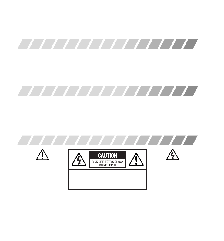
SAFETY PRECAUTIONS
The lightning flash with
arrowhead symbol,
within an equilateral
triangle is intended to
alert the user to the
presence of uninsulated “dangerous
voltage” within the product’s enclosure
that may be of sufficient magnitude to
constitute a risk of electric shock to
persons.
CAUTION : TO REDUCE THE RISK OF ELECTRIC SHOCK,
DO NOT REMOVE COVER (OR BACK).
NO USER SERVICEABLE PARTS INSIDE.
REFER SERVICING TO QUALIFIED SERVICE PERSONNEL.
The exclamation point
within an equilateral
triangle is intended to
alert the user to the
presence of important
operating and maintenance (servicing)
instructions in the literature
accompanying the appliance.
EG-2
Page 3

WARNING :
To prevent fire or shock hazard, do not expose this appliance to rain or moisture.
To avoid electrical shocks, do not open the cabinet. Refer servicing to qualified
personnel only.
These cameras should be used with 12VDC or 24VAC.
CAUTION :
To prevent electrical shocks, do NOT use any other power source.
Regulatory Notices :
This equipment has been tested and found to comply with the limits for a Class A digital device, pursuant to
Part 15 of FCC Rules. These limits are designed to provide reasonable protection against harmful interference
when the equipment is operated in a commercial environment. This machine generates, uses, and can
radiate radio frequency energy and if not installed and used in accordance with the instructions, may cause
harmful interference to radio communications. Operation of this equipment in a residential area is likely to
cause interference, in which case the user will be required to correct the interference at the user’s own
expense.
EG-3
Page 4

1. Power supply
(1) Use only with a 24VAC power supply marked class 2 or 12VDC regulated power supply.
(2) Be sure to connect each lead to the appropriate terminal. Wrong connection may cause mal-
function and / or damage to the camera.
2. Operating and storage locations
(1) Do not attempt to aim the camera at the sun or other extremely bright objects that cause smear
to appear irrespective of whether the camera is operating or not. This can damage the CCD
(Charge Coupled Device).
(2) Do not place the camera in the following locations.
q Locations subjected to extremely high or low temperatures.
(operating temperature range : –10°C to +50°C {14°F to 122°F})
(storage temperature range : –20°C to +60°C {–4°F to 140°F})
w Locations subjected to high levels of humidity and dust
(storage humidity range : max 85% {no condensation})
e Locations where there are large amounts of water vapour and steam
r Locations subjected to excessive vibrations
(3) When this camera is installed near equipment, like a wireless communication device, that emits a
strong electromagnetic field, some irregularity such as noise on the monitor screen may happen.
3. Handling of the unit
Do not allow the camera to be subjected to strong impacts or shocks. The camera could be
damaged by improper handling or storage.
-Never attempt to disassemble or modify the camera.
-If an abnormality should occur, immediately turn off the power and consult your dealer.
-Never open the housing of any power supply during cleaning.
-After installation, ensure that all cables are laid in such a way that they cannot be kinked or
crushed or damaged in any other way.
EG-4
Page 5

PART DESCRIPTION
2
3 7
SYNC
L.LONINT
OFF
BLC
AGC
OFFON
ATWAWB
W/B
9
6 5 4
DC IRIS
DC
PHASE
IRIS
AES
VIDEO
1
8
① Tripod adaptor
② CCD cover
③ Dip switches
④ Line phase adjustment buttons
⑤ Auto iris mode switch
⑥ DC iris level adjustment volume
12
11 10
POWER
+12VDC
GND
VIDEO
CLASS 2
ONLY
OUT
AC24V
Pin assignment of auto iris lens connector
Pin No. DC iris Video iris
1 Control - Vcc +
2 Control + Not used
3 Drive + Video
4 Drive - Ground
⑦ Back focus lock screw
⑧ Auto iris lens connector
⑨ Back focus adjustment screw
⑩ Power LED
⑪ BNCconnectorforvideooutput
⑫ Power input connector
EG-5
Page 6

INSTALLATION
CONNECTION OF POWER SUPPLY CABLE
12VDC
24VAC
class 2 only
CLASS 2
ONLY
Connect to the 12VDC
power supply. Please refer
to the drawing on the left.
GND+12VDC
Connect to the 24VAC
power supply. If necessary,
adjust the line phase to
synchronize the image.
Please refer to the drawing
on the left.
AC24V
NOTE
When using DC power, check for
proper polarity before connecting
to power supply.
LINE PHASE ADJUSTMENT
If necessary, adjust the line phase to
PHASE
synchronize the image by pressing
PHASE adjustment button.
NOTE
In case 12VDC power supply is used, this
function is not available.
NOTE
In case the line phase cannot be adjusted
(Phase difference is more than 1800),
exchange the polarity of AC power input.
EG-6
Page 7

LENS MOUNTING
2
1
Remove the CCD cover. Then
attach the CS mount lens to
the camera. Please refer to the
drawing on the left.
CAUTION
Be cautious not to use Auto
Iris Lens with over 75mA
DC IRIS LEVEL
DC IRIS
ADJUSTMENT
DC iris level is preset in the
factory. Only if necessary, adjust
the DC iris level to achieve the
proper picture with AGC off.
AUTO IRIS MODE SELECTION
POSITION LENS
AES
VIDEO
DC
DC DC iris lens
AES Manual or fixed iris lens
VIDEO Video iris lens
BACK FOCUS ADJUSTMENT
Set the auto iris mode selection
switch to the position that
corresponds to the lens which is
mounted to the camera.
Please refer to the table on the left.
If back focus has to be adjusted after mounting
the lens, (1) loosen the back focus lock screw on
the left side of the camera with a (+) screwdriver,
(2) turn the back focus adjustment screw on the
right side of the camera with a (-) screwdriver until
screw
1 3
DIP SWITCH
SETTING
screw
2
DIP switch on the left side of the camera
allows you to set the functions of the camera.
Please refer to the following table.
the desired focus is reached, (3) tighten the back
focus lock screw.
1
2
3
4
factory setting
No. NAME POSITION FUNCTION
Synchronization mode L.L. Line lock mode
1
(SYNC) INT. Internal synchronization mode
Back light compensation ON sets to this position when strong light comes in behind the target
2
(BLC) OFF normal position
Auto gain control ON AGC level varies from 0dB to maximum 20dB
3
(AGC) OFF normal position
White balance AWB adjusts WB automatically and fixes it in 5sec
4
(WB) ATW tracks and adjusts WB automatically
EG-7
SYNC
BLC
AGC
W/B
L.L INT
ON OFF
ON OFF
AWB ATW
Page 8

MOUNTING BRACKET
Tighten the screw to attach
the bracket. Refer to the
above drawing.
SPECIFICATION
Model No. CL-301 CLH-401
TV System NTSC
Scanning System 2:1 Interlaced
Image Sensor 1/3” IT. CCD
Effective Elements ( H x V ) 510 x 492 768 x 494
Scanning Frequency ( H / V ) 15.734 kHz / 59.94 Hz
Video Output 1.0V (p-p) / 75Ω
Resolution ( Horizontal ) 330 TV lines 480 TV lines
Minimum Illuminance (50IRE) 0.8 lux (F1.2) 1.6 lux (F1.2)
AGC +20dB
S/N Ratio ( AGC Off ) More Than 48 dB
γ Characteristic 0.45
Auto Electric Shutter ( AES ) 1/60 - 100,000 Sec.
Sync. System INT. / L.L.
White Balance AWB / ATW
Power Supply 12VDC/24VAC
Power Consumption Less Than 3.5 W
Ambient Temperature Operation : –10°C +50°C / Storage : –20°C +60°C
Ambient Humidity Operation : RH80% Max. ( Keep Free From DAMP ) / Strage : RH85%
External Dimensions 55 (W) x 40 (H) x 102.4 (D) mm
Weight 280g approx.
Input / Output
Video Output : BNC
Power Input : Screwless 2 Pins Terminal
Printed in KOREA
 Loading...