

Page 1
9" B/W MONITOR
CEM-09/09A-2
12" B/W MONITOR
CEM-12/12A-2
OPERATION
MANUAL
Page 2
CONTENTS
PRECAUTIONS FOR USE AND INSTALLATION
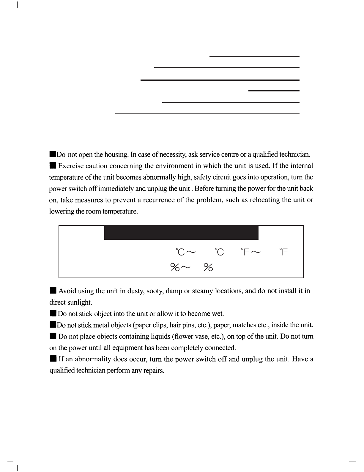
OPERATION CONDITIONS
TEMPERATURE -10 +50 (14 122 )
HUMIDITY 10
90 (No condensation)
PRECAUTIONS FOR USE AND INSTALLATION
IMPORTANT SAFEGAURDS
SAFETY INSTRUCTIONS
INSTRUCTION MANUAL CLASS B COMPUTING DEVICES
PART NAMES AND FUNCTIONS
SPECIFICATION
1
2
3
5
6
9
Page 3
CAUTION-TO PREVENT ELECTRICAL SHOCK, DO NOT REMOVE THIS
COVER. NO USER-SERVICEABLE PARTS INSIDE REFER
SERVICING TO QUALIFIED SERVICE PERSONNEL.
WARNING-TO PREVENT DAMAGE WHICH MAY RESULT IN FIRE OR
SHOCK HAZARD, DO NOT EXPOSE THIS APPLIANCE TO RAIN
OR MOISTURE.
THIS DEVICE COMPLIES WITH PART 15 OF THE FCC RULES.
OPERATION IS SUBJECT TO THE FOLLOWING TWO
CONDITIONS:(1) THIS DEVICE MAY NOT CAUSE HARMFUL
INTERFERENCE AND (2) THIS DEVICE MUST ACCEPT
ANY INTERFERENCE RECEIVED, INCLUDING INTERFERENCE
THAT MAY CAUSE UNDESIRED OPERATION.
THIS DEVICE COMPLIES WITH DHHS RULES 21 CFR
SUBCHAPTER J APPLICABLE AT DATE OF MANUFACTURE.
WARNING-SHOCK HAZARD-DO NOT OPEN
AVIS-RISQUE DE CHOC ELECTRIQUE-NE PAS OUVRIR
IMPORTANT SAFEGAURDS
Page 4

WARNING
1.Read all of these instructions.
2.Save these instructions for later use.
3.Unplug this television equipment from the wall outlet before cleaning, Do not use
liquid cleaners or aerosol cleaners. Use a damp cloth for cleaning.
4.Do not use attachments not recommended by the television equipment manufacturer as
they may result in the risk of fire, electric shock, or injury to persons.
5.Do not use this television equipment near water-for example, near a bathtub,
washbowl, kitchen sink, or laundry tub, in a wet basement, or near a swimming pool,
or the like.
6.Do not place this television equipment on an unstable cart, stand, or table. This
television equipment may fall, causing serious injury to a child or adult, and serious
damage to the equipment. Use only with a cart or stand recommended by the
manufacturer, or sold with the television equipment. Wall or shelf mounting should
follow the manufacturer’s instructions, and should use a mounting kit approved by the
manufacturer.
6A.Television equipment and cart combination should be moved
with care. Quick stops, excessive force, and uneven surfaces
may cause the equipment and cart combination to overturn.
7.Slots and openings in the cabinet and the back or bottom are
provided for ventilatio and to ensure reliable operation of the
television equipment and to protect it from overheating, these
openings must not be blocked or covered. The openings should
never be blocked by placing the television equipment on a bed,
sofa, rug, or other similar surface.
(This television equipment should never be placed near or over a radiator or heat
register.)This television equipment receiver should not be placed in a built-in
installation such as a bookcase unless proper ventilation is provided.
8.This television equipment should be operated only from the type of power source
indicated on the marking label. If you are not sure of the type of power supplied to
your home, consult your television dealer or local power company. For television
equipment designed to operate from battery power, refer to the operating instructions.
9.This television equipment is provided with a polarized alternating-current line plug(a
plug having one blade wider than the other). This plug will fit into the power outlet
only one way. This is a safety feature. If you are unable to insert the plug fully into the
outlet, try reversing the plug. If the plug should still fail to fit, contact your electrician
to replace your obsolete outlet. Do not defeat the safety purpose of the polarized plug.
Alternative Warning-This television equipment is provided with a three-wire grounding
type plug having a third (grounding) pin. This plug will only fit into a grounding-type
SAFETY INSTRUCTIONS
Page 5

power outlet. This is a safety feature. If you are unable to insert the plug into outlet,
contact your electrician to replace your obsolete outlet. Do not defeat the safety
purpose of the grounding-type plug.
10.Do not allow anything to rest on the power cord. Do not locate this television
equipment where the cord will be abused by persons walking on it.
11.For added protection for this television equipment during a lighting storm, or when it
is left unattended and unused for long periods of time, unplug it from the wall outlet.
This will prevent damage to the epuipment due to lightening and power line surges.
12.An outside antenna system should not be located in the vicinity of overhead power
lines or other electric light or power circuits, or where it can fall into such power
lines or circuits. When installing an outside antenna system, extreme care should be
taken to keep from touching such power lines or circuits as contact with them might
be fatal.
13.Do not overload wall outlets and extension cords as this can result in fire or electric
shock.
Never push objects of any kind into this television equipment through cabinet slots as
they may touch dangerous voltage points or short out parts that could result in a fire
or electric shock. Never spill liquid of any kind on the television equipment.
14.Do not attempt to service this television equipment yourself as opening or removing
covers may expose you to dangerous voltage or other hazards. Refer all servicing to
qualified service personnel.
15.Unplug this television equipment from the wall outlet and refer servicing to qualified
service personnel under the following conditions:
a.When the power cord of plug is damaged or frayed.
b.If liquid has been spilled into the television equipment.
c.If the television equipment has been exposed to rain or water.
d.If the television equipment does not operate normally by following the operating
instructions. Adjust only those controls that are covered by the operating
instructions as improper adjustment of other controls may result in damage and
will often require extensive work by a qualified technician to restore the television
equipment to normal operation.
e.If the television equipment has been dropped or the cabinet has been damaged.
f.When the television equipment exhibits a distinct change in perfomance-this
indicates a need for service.
16.When replacement parts are required, be sure the service technician has used
replacement parts specified by the manufacturer that have the same characteristics as
the original part. Unauthorized substitutions may result in fire, electric shock, or
injury to persons.
Page 6

INSTRUCTION MANUAL CLASS B COMPUTING DEVICES
Sub-brightness, Focus , V-Hold , V-Size controls located on the rear panel are for
special adjustments which should be performed only by qualified service personnel.
Page 7

PART NAMES AND FUNCTIONS
CEM-09-2/CEM-09A-2
Page 8

CEM-12-2/CEM-12A-2
Page 9

1. POWER SWITCH
Press the switch to turn the power ON, and press again to turn the power OFF.
2. POWER LED
The LED indicator goes on when the power is turned on.
3. BRIGHTNESS CONTROL
For adjustment of picture brightness.
4. CONTRAST CONTROL
For adjustment of picture contrast.
5. V-SIZE CONTROL
For adjustment of V-SIZE.
5a.VOLUME CONTROL
For adjustment of audio volume.
6. AUDIO OUTPUT TERMINAL(RCA connector)
Connect with the input terminal of the related audio equipment.
7. AUDIO INPUT TERMINAL(RCA connector)
Connect with the output terminal of the related audio equipment.
8. TERMINATION(High/75
impedance)SWITCH
Select the input impedance, High/75
-impedance.
When using only one monitor, turn the termination switch to the "75
"position.
When using morn than one monitor, position all the termination switches on the
monitors to the "HI". But in the last monitor the termination switch should be in
the "75
"position for proper line termination.
9. VIDEO OUTPUT TERMINAL(BNC connector)
Connect with the input terminal of the related video equipment.
10. VIDEO INPUT TERMINAL(BNC connector)
Connect with the output terminal of the related video equipment.
11. POWER SOCKET
Connect to power source.
12.V-SIZE
For adjustment of a suitable height size on screen.
13.SUB-BRI
For sub-adjustment of picture brightness.
14.FOCUS CONTROL
The focus control can be adjusted for optimum focus.
15.V-HOLD
For adjustment of V-HOLD.
Page 10

9
SPECIFICATION
CEM-09-2/CEM-09A-2
CEM-12-2/CEM-12A-2
Design and specifications are subject to change without prior notice.
Model No.
Screen size
TV system
Resolution
Input signal
Input impedance
Video output
Power Source
Power consumption
Audio output
Dimensions (W
H D)
Net weight
EIA or CCIR
center:1000 lines
corner:800 lines
composite video 1.0Vp-p, 75
75 /Hi-impedance, swichable
composite video 1.0Vp-p, loop-through
AC100-240V~50/60Hz
CEM-12-2 CEM-12A-2
0.5W W/H speaker 1 1W W/H speaker 1
CEM-09-2
CEM-09A-2
12" measure diagonally10" measure diagonally
30W max.20W max.
222
238 250mm 304 320 310mm
4.7kg 8.0kg
Page 11

Page 12

312-0184-101
 Loading...