

Page 1
VOL UME
MIN
MAX
VACU UM TUBE INT EGRAT ED AMPLIFIE R MT -35 MK2
SEL ECTO R
LIN E1
LIN E2
LIN E3
MT- MK35 2
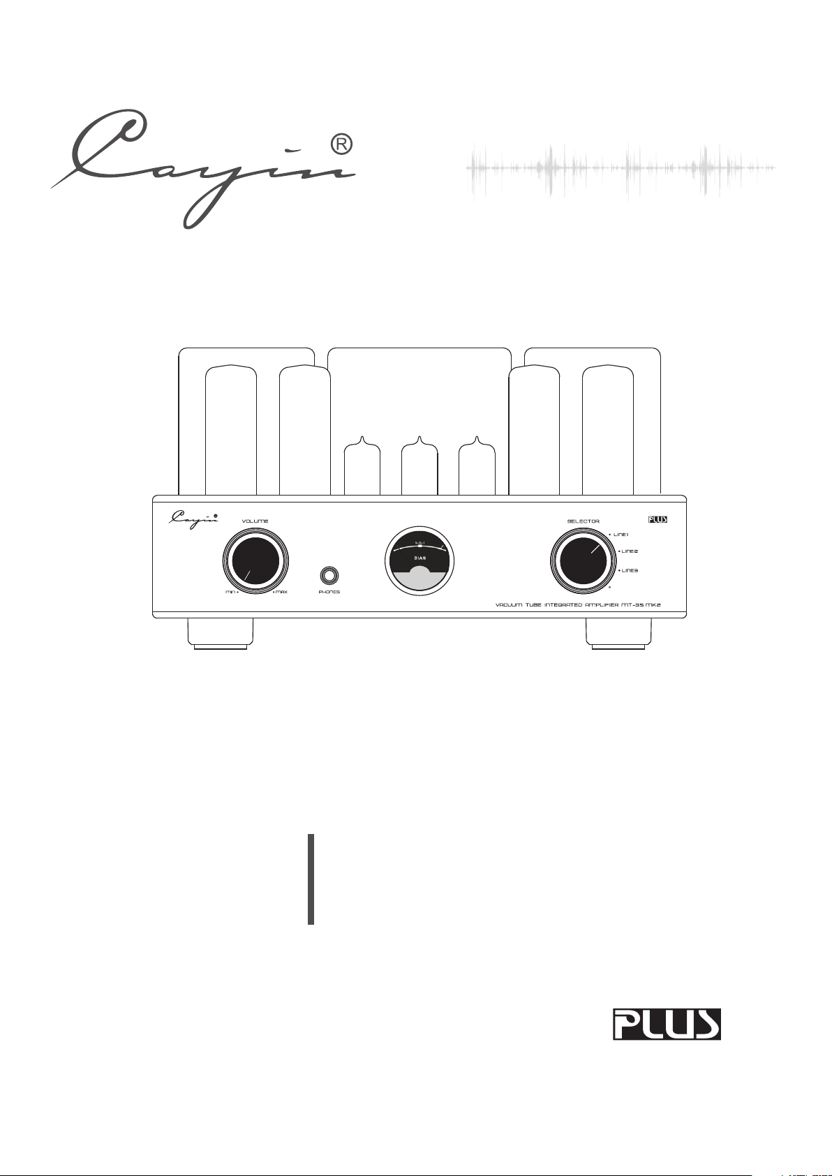
Vacuum Tube Integrated Amplifier
User's Manual
Page 2

Thanks for choosing Cayin MT-35 MK2 Vacuum Tube Amplifier and please read the user's
manual carefully before installation and operation.
In order to prevent damage during transportation, the amplifier is packed with protective foams surrounding
the tubes. Before installation and operation, please remove these foams to avoid any risks.
Integrated
Table of Contents
Table of Contents……………………………………………………………………… ………… 1
Package Contents
Product Features
Safety Precautions
Specifications
Maintenance…………………………………………………………………………………………………………………5
Warranty Service
Precautions
Front Panel
Rear Panel
Top Panel
Installation
…………………………………………………………………………………………………………………7
…………………………………………………………………………………………………………………8
……………………………………………………………………………………………………………………9
…………………………………………………………………………………………………………………10
…………………………………………………………………………………………………………2
……………………………………………………………………………………………………………3
…………………………………………………………………………………………………………3
………………………………………………………………………………………………………………4
……………………………………………………………………………………………………………5
…………………………………………………………………………………………………………………6
………………………
Tube Replacement
Audio Connection
Speaker Connection
Turning on
Small Tips …………………………………………………………………………………………………………………13
Troubleshooting
1
…………………………………………………………………………………………………………………13
………………………………………………………………………………………………………10
…………………………………………………………………………………………………………11
………………………………………………………………………………………………………12
…………………………………………………………………………………………………………14
Page 3

NOTE:
Cayin MT-35 MK2 Vacuum Tube Amplifier is designed and manufactured with our original parts and
reaching the best results. We are not responsible for problems and damages caused by non-original parts
replacement in the amplifier.
Integrated
Package Contents
Please carefully check the package first and then open it.
Package contents include:
1. Cayin MT-35 MK2 1 piece;
2. Main Fuse 2 pieces;
3. Power cord 1 piece;
4. User's Manual 1 piece;
Recommendation:
Keep all packing materials for future use .
NOTE:
Please make sure local voltage level is matched with the input level of the amplifier,which indicates on the rear
panel. Too low or too high voltage may cause problem. Please contact our company or our local agent if you've
found improper voltage.
All other parts except above are not included.
2
Page 4

Product Features
◆ Hand-made construction with the finest point-to-point wiring.
◆ Two EI output transformers with wide bandwidth are applied.
◆ Specially designed toroid transformer for power supply.
◆ 5BK7A tubes are used in the preamp stage.
◆ Four EL34 tubes are used for AB1 push-pull amplification.
◆ External user Bias Adjustment is accessible with the BIAS meter for monitoring on the top of the amplier.
Headphone output jack has been used.
◆
Triode and Ultralinear selection.
◆
◆ High-quality Japanese ALPS potentiometer.
◆ Equipped with easily-installed tube cover for protection.
Safety precautions
1. Unplug the power cord if you are not going to use the product for an extended period of time.
2. The machine will become hot after working for a long time. Please keep the unit's ventilation open and install
the amplifier at a well-ventilated place to avoid troubles and fire hazard.
3. Forbidden to operate when the output is open or shorted.
4. Do not attempt to service this product yourself. Opening the cover may expose you to dangerous voltage or
other hazards.
5. We are not responsible for any problems caused by checking and opening without permission of our
company. For service, Please contact a qualified service technician.
6. Do not place any objects filled with liquids such as vases or some others on the top or around.
7. Clean only with dry cloth.
8. Please move the amplifier carefully not to drop the unit or be subject to other strong shocks.
3
Page 5
◆ To reduce the risk of electric shock, do not remove the cover.
ITEM
SPECIFICATIONS
【 】Power Output
TR:18W+18W (RMS )
UL:35W+35W ( )
Triode mode
RMS Ultralinear mode
【 】 Frequency Response
8Hz~55KHz (-3dB)
【 】THD
1%(1kHz)
【 】S/N Ratio
89dB
【 】 Input Sensitivity
300mV
【 】Input Impedance
100kΩ
【 】Output Impedance
4 , 8ΩΩ
【Headphone 】Output Impedance
16Ω~300Ω
【Input Connector】
LINE1, LINE2,LINE3
【 × × 】W D H
326mm×272mm×184mm
【 】Tube
12AX7×1、12AU7×2、EL34×4
【 】Net Weight
13.5kg
【Power Consumption】
260W
【Working Condition】
Temp:0℃~40℃ Humidity: 20%~80%
【Storage Condition】
Temp:-20℃~70℃ Humidity: 20%~90%
CAUTION
RISK OF ELECTRIC SHOCK
DO NOT OPEN
◆ No user serviceable parts inside. Refer servicing to qualified
service personnel.
◆ To reduce the risk of fire or electronic shock, do not expose
the unit to rain or moisture.
The lightning flash with arrowhead symbol is intended to alert user to the presence of uninsulated
“dangerous voltage” within the product's enclosure that may be of a risk shock to persons.
The exclamation point is intended to alert user to the presence of important operation and maintenance
(servicing) instructions accompanying the appliance.
Specifications
4
Page 6
Maintenance
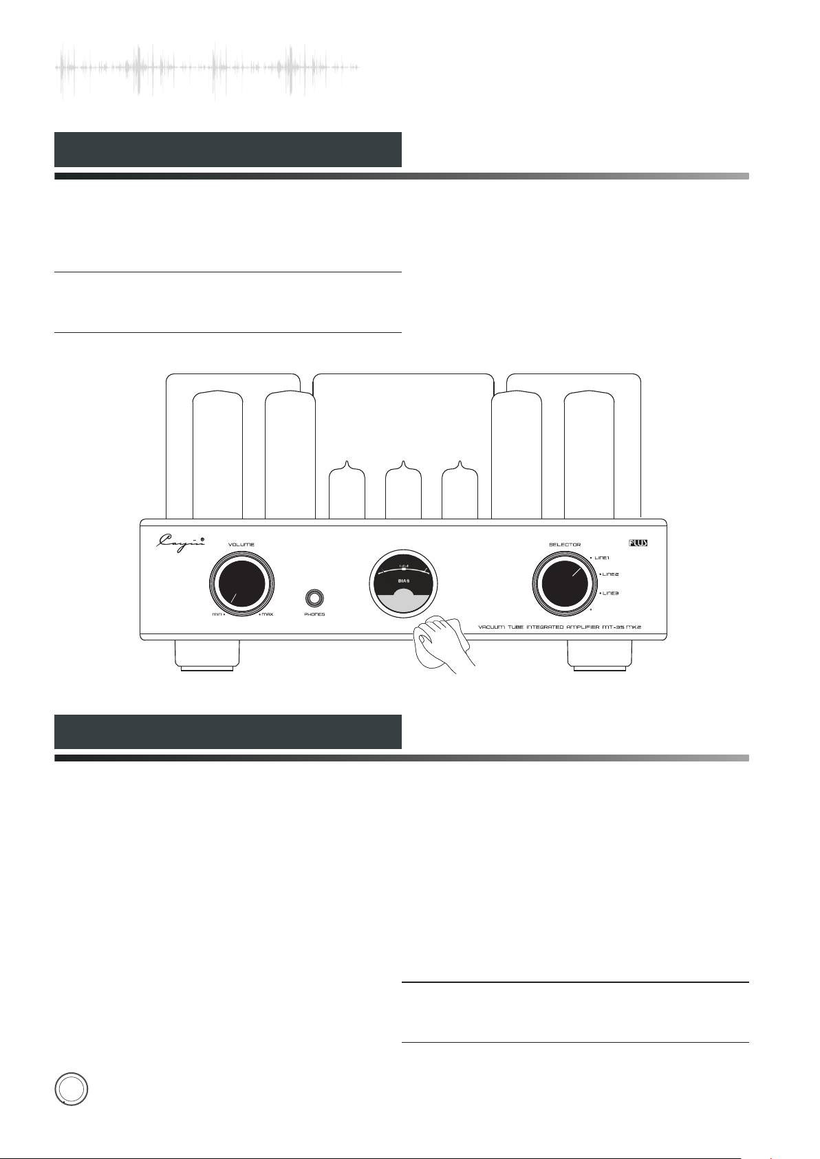
NOTE:
◆ ◆ Use the soft dry cloth to clean up the chassis regularly.
Do not use any chemicals for cleaning.
VOL UME
MIN
Warranty Service
MAX
VACU UM TUBE INT EGRAT ED AMPLIFIE R MT -35 MK2
SEL ECTO R
LIN E1
LIN E2
LIN E3
1.This product is warranted for a period of twelve months beginning from the date of purchase.
2.The defective product must be returned to your dealer or our company for repairing when your dealer or our
company accepts your requirement.
3.The warranty doesn't extend to any product that has been opened by you without permission of our company.
NOTE:
The information in this manual is subject to change
without further notice.
5
Page 7
Precautions
Connected to the power socket
INP UT
LIN E1
ZHU HAI SP ARK EL ECTR ONIC E QUIP MENT C O., LTD.
LIN E2
LIN E3
SPEAK ER OUTPUTRIG HT
M MKT-35 2
48
LEF T SPEAK ER OUTPUT
4 8
CAUT ION
RISK OF ELECTR IC SHOCK
DO NOT OPEN
260
YALIDA
YN-401
Connected to AC Input
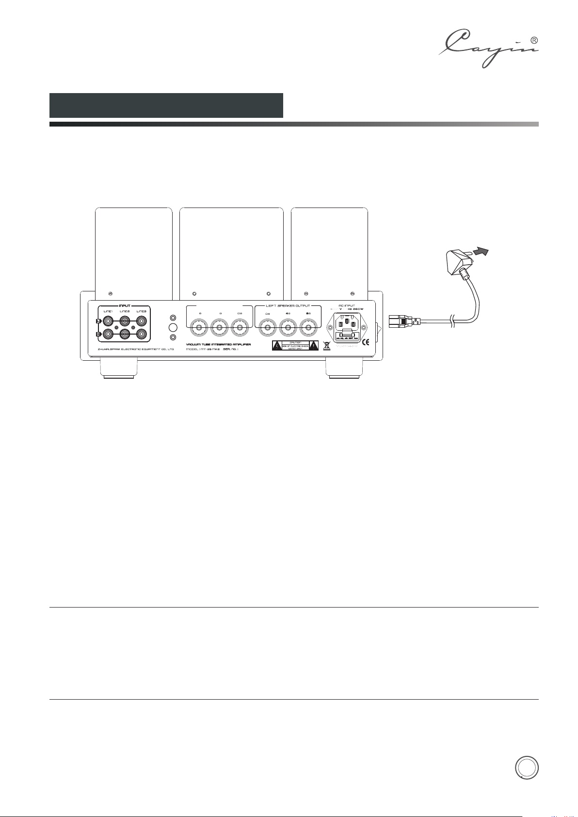
Connection of power cord:
Connect the speaker cables and signal cable first and then insert the power cord into the power socket.
NOTE:
◆ Connect the power only after finishing other connections.
It is normal that power transformer becomes hot for extended period of operation.
◆
Unplug the power cord if you're not going to use the product for an extended period of time.
◆
Please make sure corresponding voltage is the same as required. We are not responsible for damage caused
◆
by misuse of unsuitable voltage.
6
Page 8
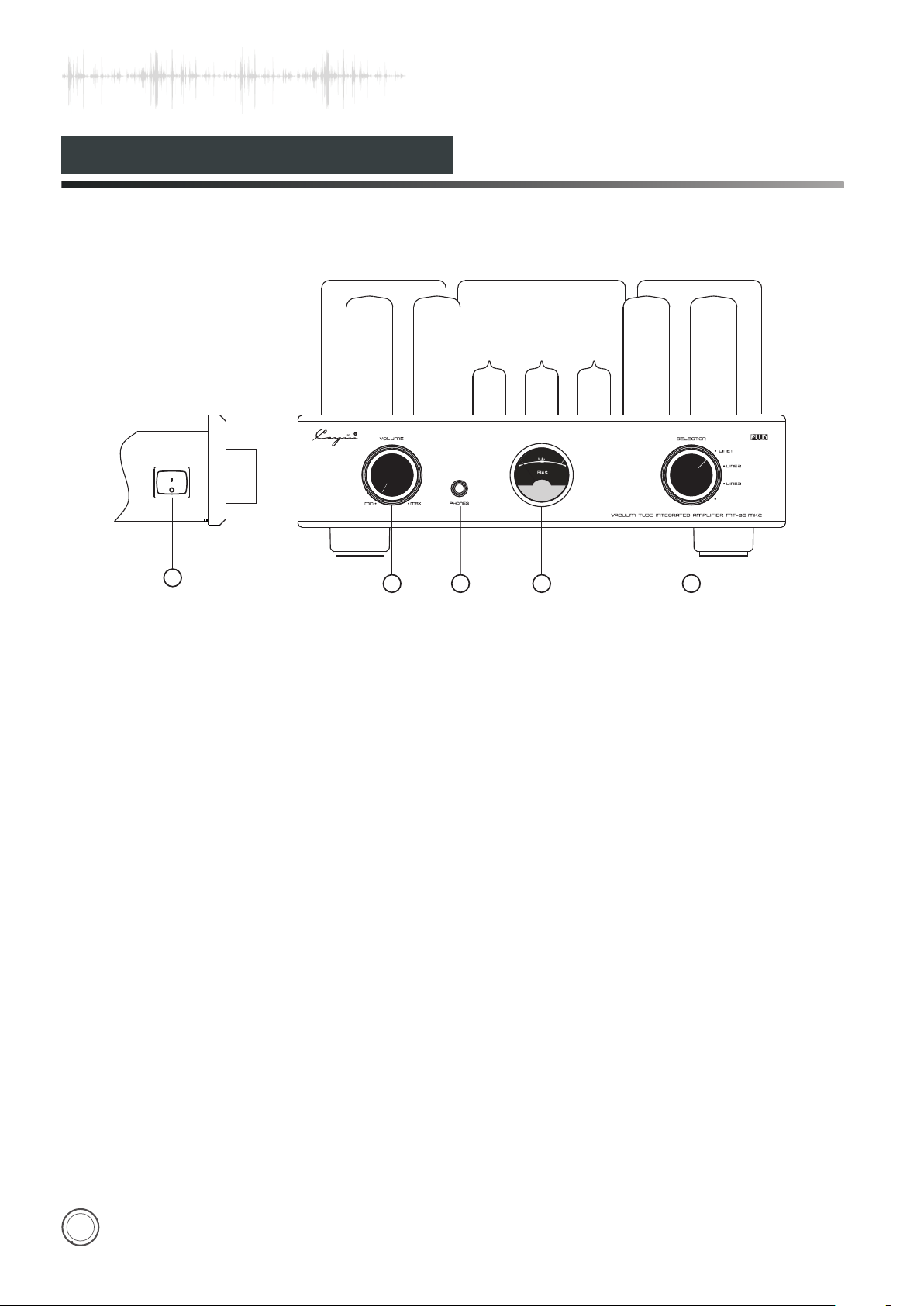
Front Panel
VOLU ME
POW ER
ON
OFF
1
MIN
2
1.Power Switch
Used to switch on/off the amplifier.
2.Volume Knob
Used to control volume
3.
Headphone Socket
Let you enjoy the high-quality music with
headphone.
4. BIAS Meter
Used to mornitor the working current of
the power tube.
Backlight of the Meter is on when
switching on.
SELE CTOR
LIN E1
LIN E2
LIN E3
MAX
3
VACU UM TU BE I NTEGR ATED AMPLI FIER MT-35 MK2
54
Diagram 1
5. Input Selector
Used to choose 4 types of audio sources.
You can hear sound from LINE1 when LINE1 indicator is on.
You can hear sound from LINE2 when LINE2 indicator is on.
You can hear sound from LINE3 when LINE3 indicator is on.
7
Page 9
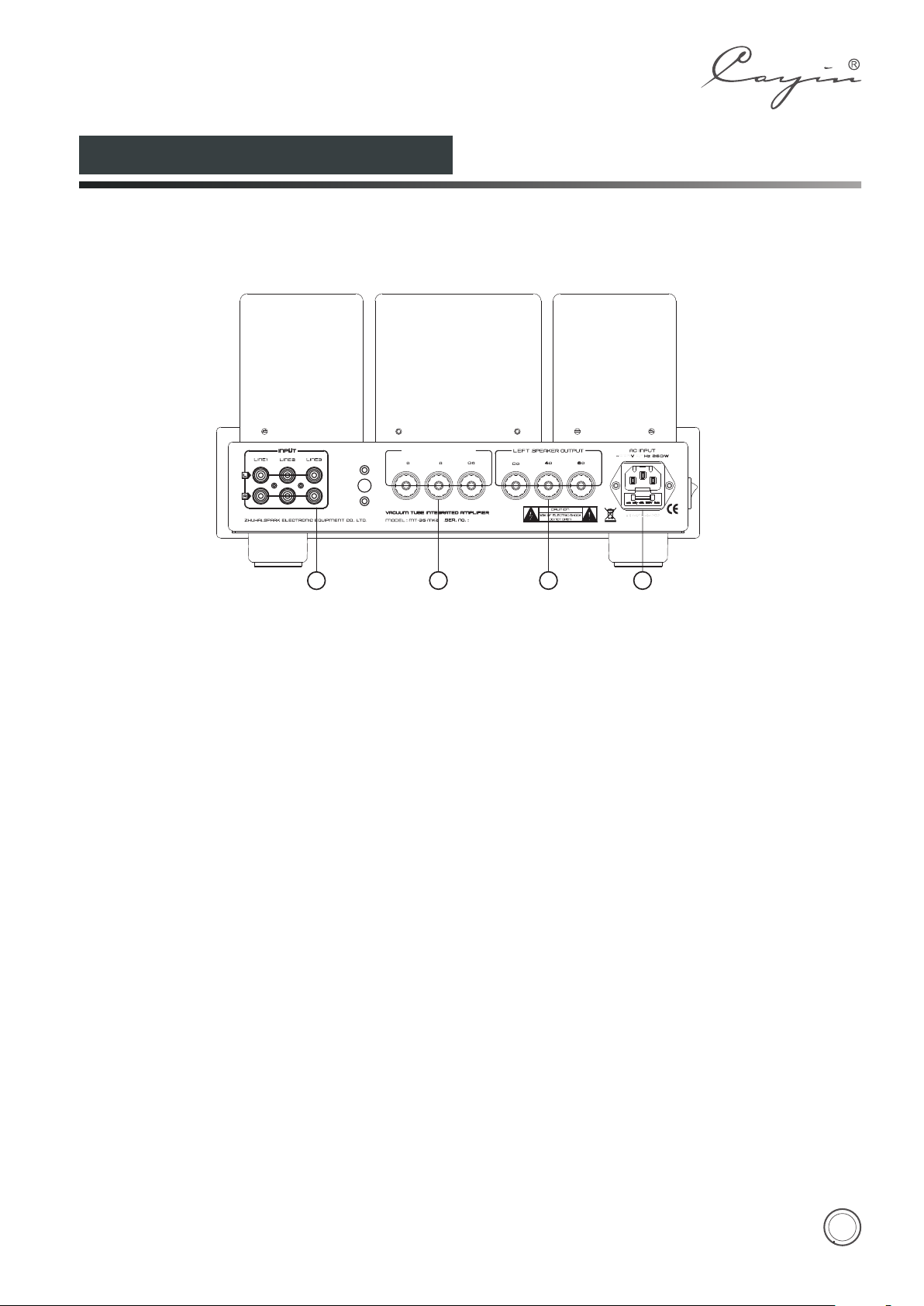
Rear Panel
INP UT
LIN E1
ZHU HAI SP ARK EL ECTR ONIC E QUIP MENT C O., LTD.
LIN E2
LIN E3
1
1. Signal Input Terminal
Used for audio source input.
2. Right Channel Output
Used to connect with the right channel of speaker.
3. Left Channel Output
Used to connect with the left channel of speaker.
SPEAK ER OUTPUTRIG HT
48
M MKT-35 2
2
Diagram 2
LEF T SPEAK ER OUTPUT
4 8
CAUT ION
RISK OF ELECTR IC SHOCK
DO NOT OPEN
3
260
4
4. Power Socket with Main Fuse
Main fuse is located just below the power socket.
Replace the fuse with the same type as indicated.
8
Page 10
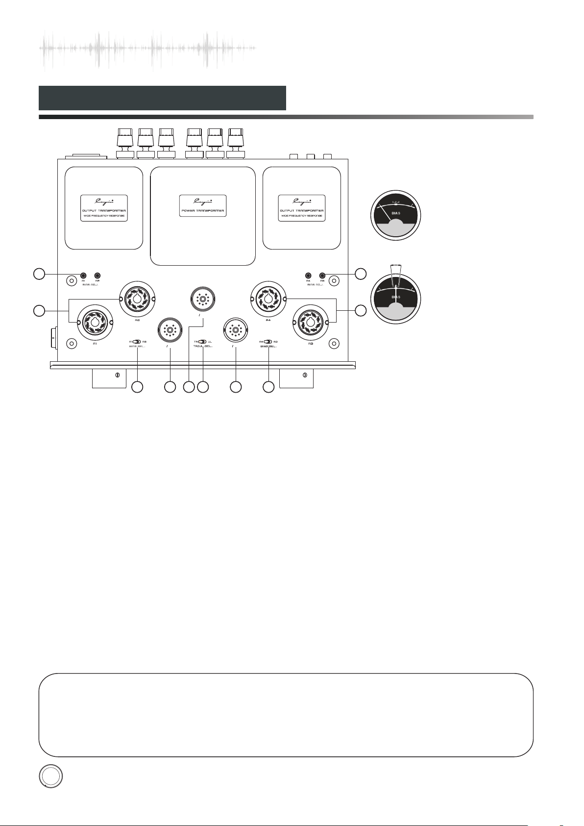
Top Panel
V2 5B K7A
PO WER T RAN SFO RM EROU TPU T TRA NSF OR MER
V1 5B K7A
TR U L
TR UL S EL.
4
V3 5B K7A
5
WIDE FR EQUEN CY RESPON SE
1 1
2
A1
BIA S ADJ.
A2
A2
A2
A1
A1
BIA S SEL.
3 34 4
A4
A4
BIA S SEL.
A3
OU TPU T TRA NSF OR MER
WIDE FR EQUEN CY RESPON SE
A4
BIA S ADJ.
A3
A3
Diagram 3
1.
Bias Adjustment Knob for Power Tubes
(A1、A2、A3、A4)
2.A1、A2、A3、A4: EL34
Bias Selector Switch(A1、A2、A3、A4)
3.
Used to select corresponding tube for bias
adjustment.
Bias adjustment for the power tube:
Turn the BIAS SELECTOR Switch to the power tube you
are preparing to adjust. Adjust the corresponding BIAS
ADJ. small knobs with flat screwdriver, and inspect the
BIAS meter on the top panel and make sure the
pointerkeeps in the center. Bias adjustment for A1, A2,
A3, and A4 are the same. After all have been adjusted,
4.V1、V2、V3:5BK7A
do it one more time, to make sure all the bias level of A1,
Triode/ Ultralinear Indicator
5.
A2, A3, and A4 are the same.
Used to select Triode/Ultralinear working state.
Sample of Bias adjustment for power tube A1:
TR:Triode Operation State;
1. Turn the BIAS SELECTOR Switch to A1;
UL: Ultralinear Operation State.
2. Turn the BIAS ADJ. knob A1, until the pointer of the
Diagram 4
Bias me te r when no t worki ng
A
Diagram 5
Bias mete r during wo rking
2
Note: Whe n working n ormally,
the point er should stay within
the A zone, s till , it would m ove
for the vol tage fluctu ation.
bias meter keeps in the center.
The same for A2, A3, A4.
NOTE
◆ Be careful of the high temperature of the tubes during operation.
◆ Replace the tubes carefully and correctly.
◆ Power tubes must be matched for well function.
9
Page 11
Installation
Carefully read and follow the manual for installation:
◆ Do not place the machine near heat sources such as radiators, heat registers or other products that produce
heat.
◆ In order to avoid being overheated please keep the unit's ventilation open.
◆ Do not expose this appliance to rain or moisture.
◆ Keep the amplifier in a certain distance so that it can be easily connected.
◆ Amplifier should install steadily and make sure all four feet are on the same level.
◆ Keep the amplifier over 15cm's distance to the surrounding walls.
NOTE:
Please make sure local voltage level is matched with
the input level of the amplifier, which indicates on the
rear panel. Too low or too high voltage may cause
problems or shorten the amplifier's life.
Tube Replacement
Tubes for the Machine
5BK7A
EL34
Tubes Replacement
5B K7 -A
EL 34、6 CA7、6L6、588 1
10
Page 12
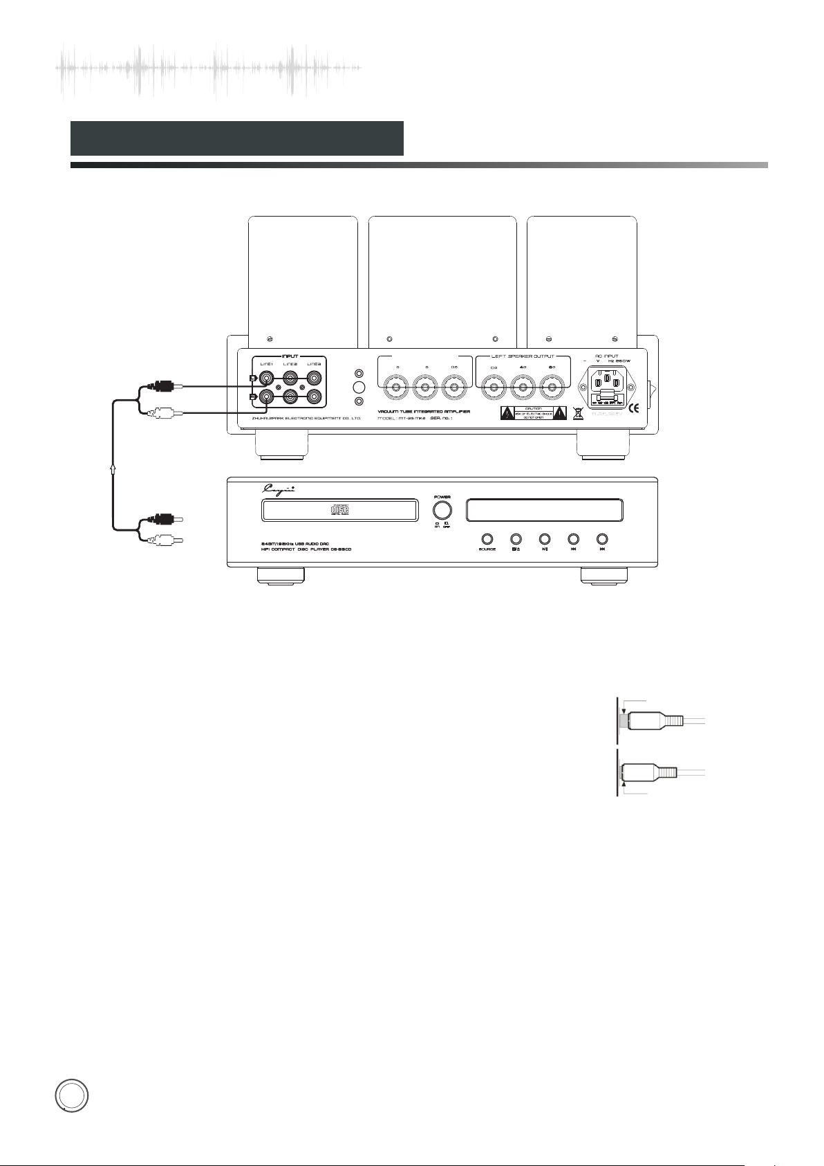
Audio Connection
Connection method of Cayin MT-35 MK2 with other audio equipments Take pictures below for your reference.
INP UT
LIN E1
ZHU HAI SP ARK EL ECTR ONIC E QUIP MENT C O., LTD.
LIN E2
LIN E3
SPEAK ER OUTPUTRIG HT
M MKT-35 2
48
LEF T SPEAK ER OUTPUT
4 8
CAUT ION
RISK OF ELECTR IC SHOCK
DO NOT OPEN
To audio
output terminal
NOTE:
Pleace refer to the manuals of other connected equipments during the installation.
•
Do not insert the power cord into the main socket before all other equipments are
•
well connected.
Rrefers to right channel while L represents left channel.
•
Please take the right guidance for connection as wrong connection may cause
•
noise, low-grade function or damage.
Do not fasten signal cable together with power cable and speaker cables. It will
•
worsen the acoustic fidelity.
260
Wrong connection
Right connection
11
Page 13
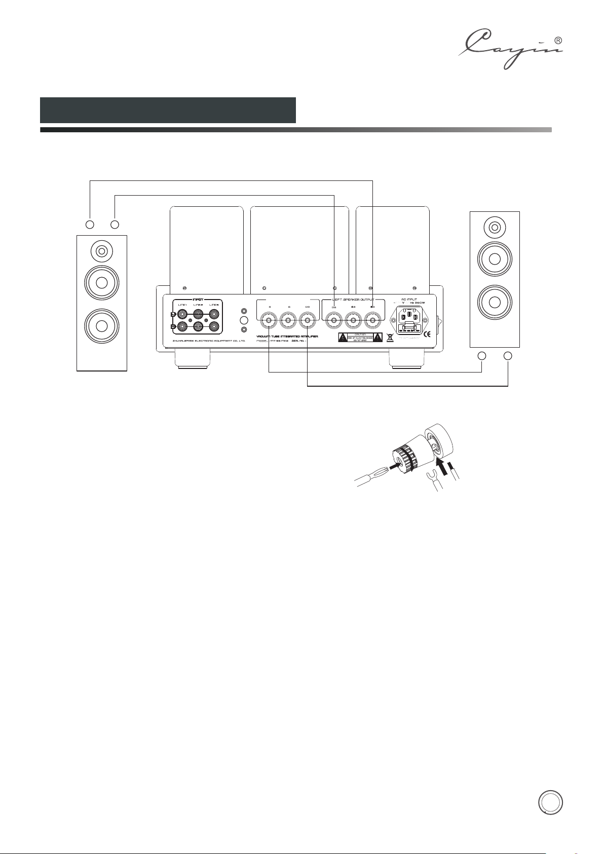
Speaker Connection
+
-
RED
BL ACK
INP UT
LIN E1
ZHU HAI SPA RK ELE CTRON IC EQU IPME NT CO., LTD.
LIN E2
LIN E3
M M KT-35 2
SPEAKER(L) SPEAKER(R)
Check the impedance of your speakers:
Attach the positive from your speaker to the 4 or 8
ohm terminal and the negative to the 0 ohm
terminals separately. If your speakers are 6 ohm, 4
ohm o r 8 ohm (re com mend ed) te rminal is
preferential and it would not cause damage to the
amplifier.Connecting the left and right speakers
according to the guidance can make sure of the
acoustic fidelity.
SPEAK ER OUTPUTRIG HT
48
LEF T SPEAKE R OUTPUT
4 8
CAUTI ON
RISK OF ELECTRIC SHOCK
DO NOT OPEN
RED
BL ACK
Banana pl ug
Connection of speaker cables:
1. Unscrew the terminal knob
2. Insert the speaker cable
3. Screw the terminal knob
NOTE:
Connect the speaker cables with the amplifier after it is
•
well connected with the speakers.
Connect both of the speakers to make sure of the
•
acoustic fidelity.
Please notice the signal direction indication of the
•
cables.
Do not mix up the positive and negative ends of speaker
•
cables or it will cause short circuit.
260
Normal pl ug
+
-
12
Page 14

Turning On
Before turning on the amplifier please make sure all connections are right and power supply is stable.
• Turn on the amplifier and the power LED will be on.
It shines and indicates that the amplifier is working.
• If the LED is not on please contact with our local
agent or our company.
• Select the right audio source channel, adjust the volume
to a certain position and then you can enjoy themusic
you prefer.
NOTE:
1. When the audio system is under working state, don't
unplug the signal cable or speaker cables, or it will
cause damage to the amplifier and other equipments.
2. It should at least takes 2 minutes before you turn on the
power again, or it will cause damage to the vacuum
tubes.
Sma l l Ti p s
Read the Manual—— Please read the user's manual carefully before installation and operation.
Keep the Manual——Please keep the manual for future reference.
Warning Signs——Don't tear off or rub off the serial number.
Operation——Do the operations as you are instructed in the Manual.
Parts—— If you are going to use parts not supplied by our company like power cord, fuses etc please
make sure that parts you used are compatible with the safety requirements. Or it will cause fire or electric
shock.
Placement——Put the amplifier on a level place. Make sure that it doesn't bring damage to the children,
adults and the amplifier itself.
Power——Please make sure the local voltage is the same level as indicated on the rear panel.
Overload——If the power socket is overloaded with other equipment, it will cause fire or electric shock.
Warranty Service——Do not open the product and change the components inside yourself. Opening
the cover may expose you to dangerous voltage or other hazards. The warranty doesn't extend to any
product that has been opened by you without permission of our company.
Troubleshooting——If any problems when you are using the product, please check according to
following tips to look for the exact reason. Please contact with our company if you can't solve the
problem.
13
Page 15
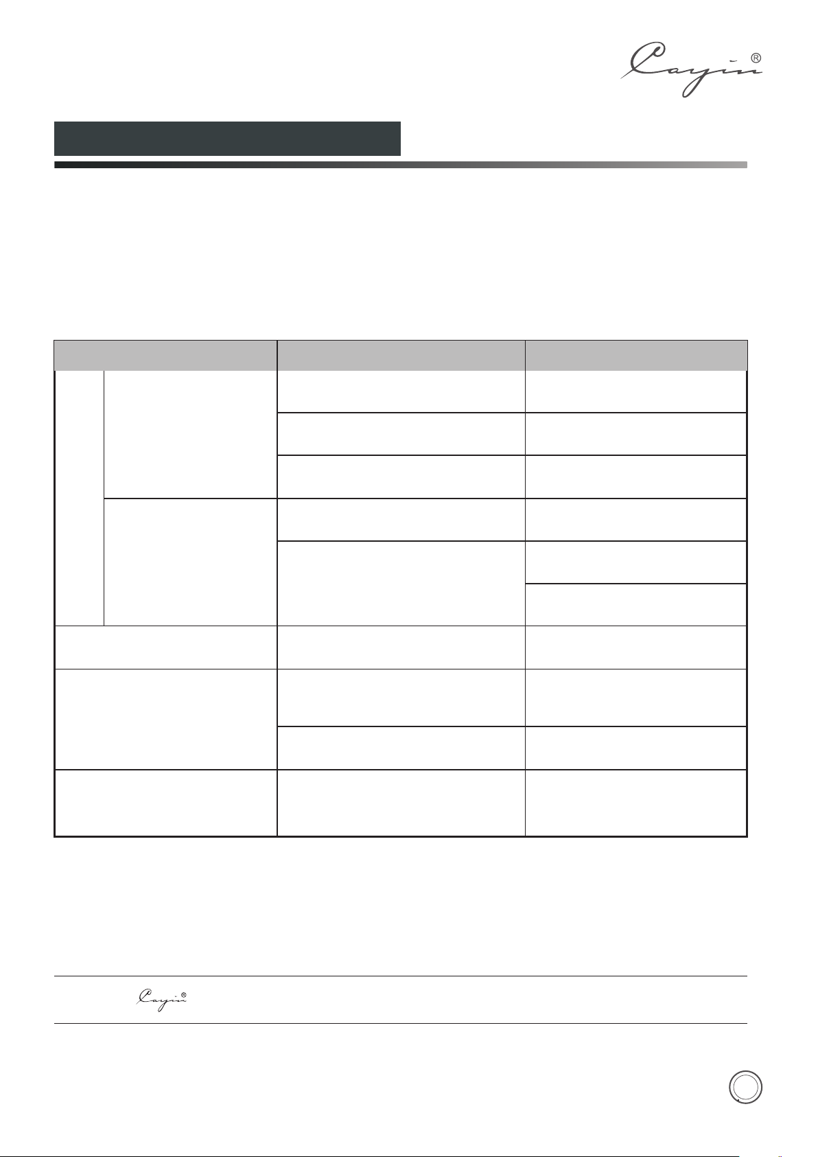
Troubleshooting
Please follow the instruction in the manual in order to keep the amplifier work in its best state. If wrongly
operated and you thought that would be troubles please check according to following tips to look for the exact
reasons.
Problem
Backlight of the Meter is Off
NO OUTPUT
Backlight of the Meter is On
Sound Distortion
Noise output
Cause
Power cord is not well-connected.
Main fuse is out.
Troubles of inner parts or components.
Volume is at ZERO.
NO signal input.
High input signal level.
Ground of input signal cable is open
or bad contact of the input signal
cable.
Components or circuits are in trouble.
Remedy
Check power cable connection
or power outlet connection
Replace with the same type
and value fuse.
Please contact with local
agents or our company.
Turn up the Volume.
Check the function of the
sound source.
Check the input selection and
switch to the proper input.
Turn down the volume to
suitable .position
Replace the input signal
cable with a new one.
Please contact with local
agents or our company.
Sound field Positioning
is not so good.
Signal input cables or speaker
cables are wrongly connected.
Reconnect it as suggested in
the manual.
NOTE: is the registered trademark of Zhuhai Spark Electronic Equipment Co., Ltd.
14
 Loading...