

Page 1
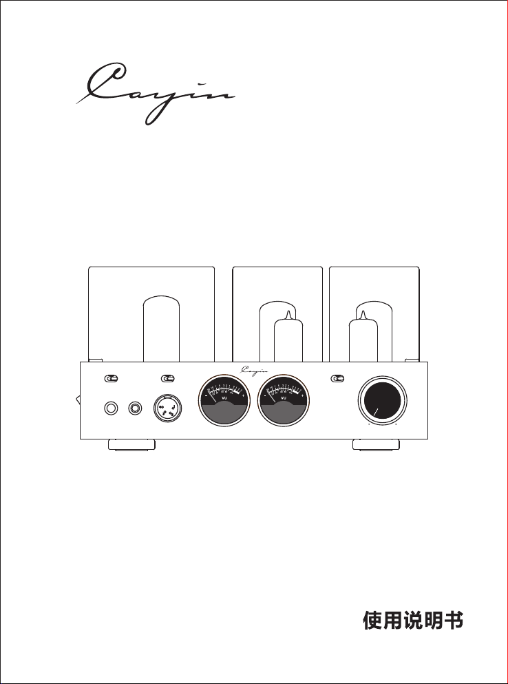
HA-2A真空管耳机功率放大器
4.4 BAL.
LM H
4PIN BAL .STD
IMPEDA NCEPHONES
4.4 BAL .
STD
4PIN BAL .
XLR RCA
SOURCE S
VOLUM E
MIN MAX
HEADPH ONE AMP LIFIE R HA- 2A
Page 2

Page 3

感谢您购买
罩内的珍珠 取出,否则会导致机器损坏或发生火灾。
Cayin HA-2A 真空管耳机功率放大器。
在使用前请仔细阅读此使用手册。
本产品在真空管罩内加装了珍珠棉,防止在运输过程中损坏真空管。在使用本产品前,请将真空管
棉
目 录
目录… …… ……… ……… ……… …… ……… ……… …… … …… ……… ……… …… ……… ……… ……1
开箱… …… ……… ……… ……… …… ……… ……… …… … …… ……… ……… …… ……… ……… ……2
安全注 意事项 ……… ……… …… ………… ……… ……… ……… ……… ……… ……… ……… …… …2
本机特 点 …… …… ……… ……… … ……… ……… … ……… ……… … …… …… ……… ……… … ……3
技术参 数 …… …… ……… ……… … ……… ……… … ……… ……… … …… …… ……… ……… … ……3
前面板 功能 说明… ……… ……… …… ……… ……… …… ……… ……… ……… …… ……… ……… …4
顶面板 功能 说明… ……… ……… …… ……… ……… …… ……… ……… ……… …… ……… ……… …5
常用真空管 代换表 …… ……… …… ……… …… ……… …… ……… …… ……… …………… …………5
后面板 功能 说明… ……… ……… …… ……… ……… …… ……… ……… ……… …… ……… ……… …6
安装… …… ……… ……… ……… …… ……… ……… …… … …… ……… ……… …… ……… ……… ……6
设备连接… …… …………… …… ……… …… …………… …… ……… …… …………… …… ……… ……7
耳机连接… …… …………… …… ……… …… …………… …… ……… …… …………… …… ……… ……8
开机… …… ……… ……… ……… …… ……… ……… …… … …… ……… ……… …… ……… ……… ……9
机器保养… …… …………… …… ……… …… …………… …… ……… …… …………… …… ……… ……9
保修… …… ……… ……… ……… …… ……… ……… …… … …… ……… ……… …… ……… ……… ……9
一般故障处 理… …………… …… …… ……… …… …… ……… …… …… …………… …… ……………10
真空管 安装示 意图 ………… ……… ……… …… ………… ……… ……… …… ………… ……… ……11
1
Page 4
● 开 箱 ---------------------------------------------------------------------------------
开箱前请仔细检查包装箱有无摔伤、破损或湿迹,并将包装箱置于箭头向上状态。打开包装箱,
装箱清单如下:
1. 一台。
HA-2A真空管耳机功率放大器
2. 产品使用说明书一本。
3. 产品保修卡一份。
4. 电源线一根。
5.
备用保险管:T500mAL250V 2只
● 安全注意 事 项 -- ----- ----- --------------------------- ----- ----- -------------------
1. 本机所用电源电 压必须 与机器后板标示的电压相符,如 长时间不使用时,应将电源插头 从交流 插
座拔下。
2. 本机长时间工作时温度较高,请勿在本机上放置物品或将本机放置在靠近暖气等有热源的地方。
3. 本机输出端不允许短路或空载,以免损坏机器。
4. 为避免遭电击请勿擅自打开机盖,内部无任何使用者操作部分,如须维修,请在专业人员指导下进
行。
5. 本机严禁遭水滴或水溅,不要放置花瓶等装满液体的物品,以免引起触电或损坏机器。
6. 每隔一段时间可用软布清理面板与外设,切忌使用化学试剂擦拭。
7. 请勿在电源线破损的情况下使用本机。
8. 搬运中注意轻拿轻放,避免损坏机器。
警 告
内部有高压
用户请勿打开机箱
◆为了避 免发生触电的危险 ,请勿拆卸上盖( 或底盖);
◆
如须维修, 应请符合资格的维 修人员进行维修;
◆为了避 免火灾及触电危险 ,请勿使本机淋湿 或受潮。
雷电箭头用来提醒使用者注意产品壳内未经绝缘的危险电压。这些电压值相当大,会
有触电危险。
警叹标记用来提醒使用者注意设备说明书中提到的重要操作说明和维修(服务)说明。
本产品适用于海拔2 000米 及以下和非热带气候条件下使用
建议:本产品采用本公司原厂零件设计,已达最佳设计使用效果,对使用非本公司原厂零件发生的故障,
导致本产品的任何损坏,均不在保修范围之内。请保留全部包装材料,需要搬运时重新打包。请及
时填好产品保修卡,寄回本公司,以便享受全面周到的售后服务。
注意:在插上电源插头之前,务必仔细核对本机后面板标示的电压是否与当地的电压相符。若您发现标示
电压与当地电压不符,请与经销商或珠海斯巴克电子设备有限公司联系。
2
Page 5

项 目
规格参数
【
出功率】
额定输
STD非平衡输出
330mW+330mW(L);550mW+550mW(M);750mW+750mW(H)
4.4 BAL.平衡输出
200mW+200mW(L);300mW+300mW(M);270mW+270mW(H)
4PIN BAL.平衡输出
800mW+800mW(L);900mW+900mW(M);1000mW+1000mW(H)
【频率响应】
20Hz~50kHz ±3dB
【总谐波失真】
0.2% (1kHz, 100mW; 额定输出功率小于5%)
【 】灵敏度
450mV~600mV
【信噪比】
100dB(A计权)
【耳机阻抗匹配】
L:8~64Ω; M:65~250Ω; H:251~600Ω
【耳机输出插座】
6.35mm非平衡耳机插座; 4.4mm平衡耳机插座; 4P IN平衡 耳机插 座
【输入阻抗】
RCA:25KΩ;XLR:10KΩ
【输入端子】
一组RCA;一组X LR
【使用真空管】
Ampere x ECF 82/ 6U8 Ampere x 17B F11 RCA 17AX 4GT×2、 ×2、 ×1
【体积】
270mm 247mm 143mm× ×
【净重】
10KG
【主保险管】
~220V-240V: ~100V-120VT500mAL250V; :T1AL250V
【整机消耗功率】
60W
【工作条件】
温度:0℃~40℃ 湿度:20%~80%
【储存条件】
温度:-20℃~70℃ 湿度:20%~90%
● 本机特点 -----------------------------------------------------------------------------
◆ 纯胆、纯手工制作,电子管电路采用手工搭棚焊接制作。
◆ 采用专为本机研制的高品质 宽频响E I输出变压器。
◆ 采用专为本机研制的高品质E I电源变 压器。
◆ 采用RCA 17AX4GT整 流管负责电压放大级独立供电。
◆ 采用分级独立供电,电压放 大电路 采用独立稳压供电,有效 降低对 功率放大电路
电源的干扰,保证 电路性 能最优,音质最佳。
◆ 单端甲类电路设计,确保音 乐原汁 原味,尽显单端放大电路 的独特 韵味。
◆ 整机采用NOS古董管,重播音 乐时透 着古董管特有的醇厚和温 润。
◆ 电压放大级使用Amperex ECF 82/ 6U8真空管。
◆ 功率放大级使用Amperex 17B F11真 空管做单端纯甲类功率放大。
◆ 配备高品质Neutrik 6. 35m m非平衡、Nippon Dic s 4.4 mm平衡 、Neutrik 4PIN平衡 耳机 。
插座
◆ 具备高、中、低三种阻抗选 择,完 美匹配各种耳机阻抗,发 挥最佳 效果。
◆ 具备XLR、RCA两组线路输入端子。
◆ 强劲输出功率,轻松推好高 阻抗的 高端耳机。
◆ 采用ALPS-27型高档音量 电位器 。
◆ 开机延时功能(约60秒)。
◆ 优异的电子管避震效果,给 你带来 真实的音质享受。
◆ 内部各单元合理布局及有效 的隔离 屏蔽,保证整机优良性能 。
◆ 方便安装的拔插式真空管防 护罩。
● 技术参数 ------------------------------------------------------------------------------
3
Page 6
● 前面板功能说明 -----------------------------------------------------------------------
POWER
ON
OFF
1
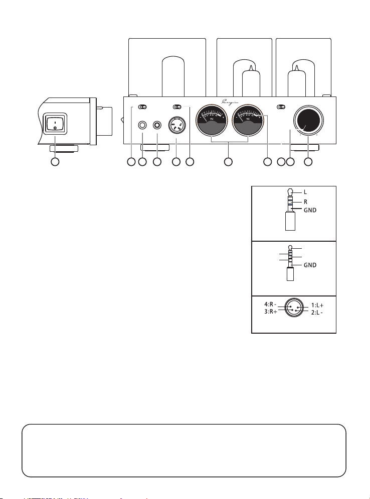
①.电源开关(POWER)
4.4 BAL.
STD
2
:
LM H
4PIN BAL .STD
IMPEDAN CEPHONES
4.4 BAL.
4PIN BAL.
453
6
7
图一:HA-2A 面板 图
XLR RCA
8
SOURCES
9 10
VOLUME
MIN MAX
HEADPHO NE AMPL IFIER H A-2A
11
用于开启和关闭功率放大器电源。
耳机输出选择开关(PHONES):
②.
用于选择非 或平衡 . 或平衡 PIN 耳机输出。
③.非平衡耳机输出插座( :
此插座用于连接6.35mm立体声插头的耳机。
4 4 4 4 BALANCE)
④. . 耳机输出插座( . :
此插座用于连接 . mm平衡立体声插头的耳机。
⑤.四 耳机输出插座( PIN :
平衡STD 4 4 BAL. 4 BAL.
STANDARD)
平衡
4 4
针平衡
4 BAL ANCE)
6.35mm耳 机插头 极性图
LR-
L+
R+
此插座用于连接四针平衡立体声插头的耳机。
⑥.耳机阻抗选择(IMPEDANCE):
用于选择相匹配的耳机阻抗,可选择L、M、H三档的耳机阻抗。
4.4mm 耳机插头极性 图平衡
当您使用耳机时,可根据使用耳机的阻抗选择相匹配的阻抗
L:8~64Ω;M:65~250Ω;H:251~600Ω)
档位(
⑦.VU电平表:
四针平衡耳机 插座极 性图
用于显示功率放大器的输出电平。
⑧.VU电平表背光源:
开启电源开关,此背光源点亮。
⑨.音源输入选择开关( :
SOURCES)
用于选择平衡输入信号或非平衡输入信号。
⑩
.音量指示灯(工作状态指示灯):
用于指示音量位置。开启电源开关,延时(约60秒)后,此指示灯亮。
⑪
.音量控制旋钮(VOLUME):
用于控制音量的大小,依照顺时针方向旋转音量逐渐增大,逆时针方向旋转音量逐渐减小。
使 用 注 意
◆ 如耳机插头为3.5mm,需使用6.35/3.5mm耳机转换座。
◆ 收听音量和时间要适度,以防损伤您的听觉系统。
◆ 使用单声道耳机插头(TS插头),会造成机器内部短路,请不要使用此类耳机插头,以免损坏机器。
◆ 当本机长时间不使用时,应该将电源插头从交流电座上拔下。
4
Page 7
● 顶面板功能说明 -----------------------------------------------------------------------
V3
17BF11
V1
V5
17AX4G T
1 3
ECF82/ 6U8
2
ECF82/ 6U8
V4
17BF11
V2
图二:HA-2A顶板 图
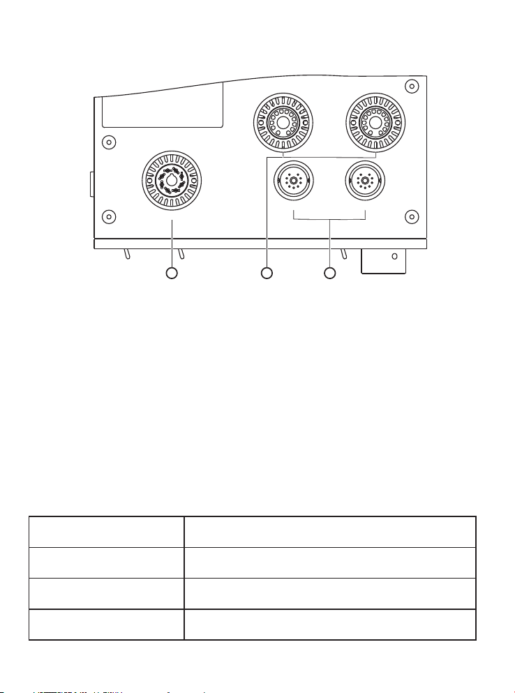
①. V5: RCA 17AX4GT真空管
②. V3、V4: Amperex 17BF11真空管
③. V1、V2: Amperex 真空管ECF82/6U8
注意: ◆工作时真空管表面温度很高,小心烫伤。
◆替换真空管时,请参阅第11页<真空管安装示意图>相应真空管的安装方法,以免损坏真空管。
◆真空管应配对使用。
● 常用真空管代换表 ---------------------------------------------------------------------
本机用真空管型号
Amperex ECF82/6U8
Amperex 17BF11
RCA 17AX4GT
ECF82、6U8
17BF11A
17AX4GTA
代换真空管型号
5
Page 8
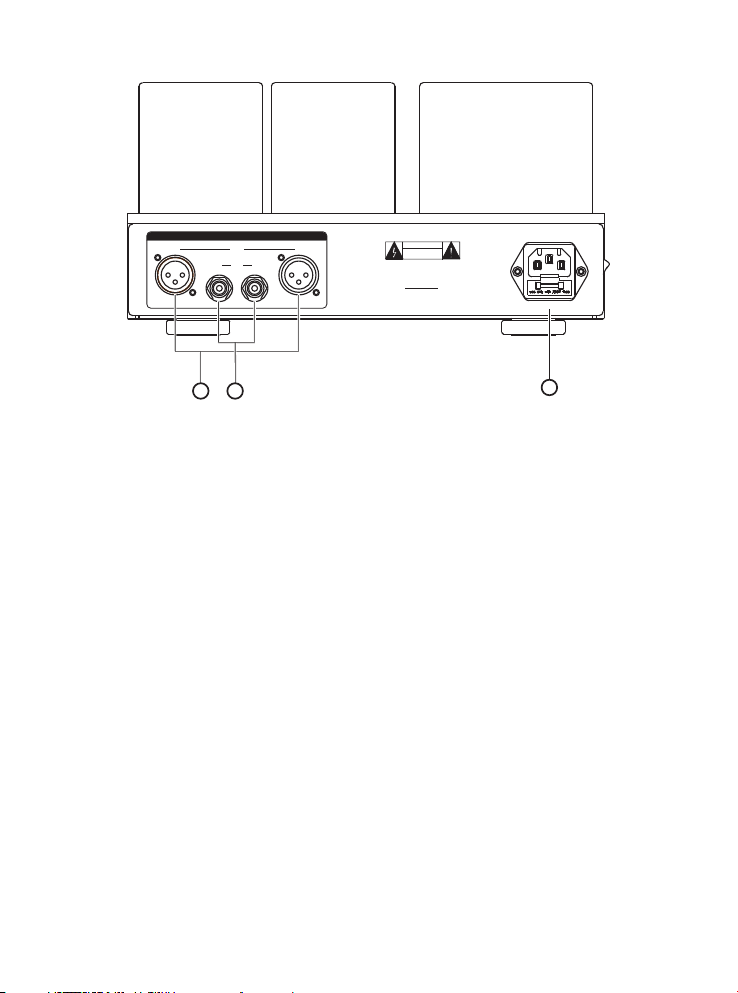
● 后面板功能说明 -----------------------------------------------------------------------
平衡输入端子(XLR):
①.
SOURC ES
R L
1:G 2:+ 3: - 1:G 2 :+ 3:-
XLR
RCA
R L
1 2
警 告
内部有高压
用户请勿打开机箱
真空管耳机 功率放大器
名 称 :
型 号 : HA 2A -
编 号 :
珠 海 斯 巴 克 电 子 设 备 有 限 公 司 制 造
ZHUHAI SPA RK ELEC TRONI C EQUIP MENT CO. , LTD.
图三:HA-2A后板 图
~220V 5 0Hz 60W
T500 AL250 Vm
3
用于外部平衡音频信号输入,请注意左右声道不要接反。
②.非平衡输入端子(RCA):
用于外部非平衡音频信号输入,请注意左右声道不要接反。
③.电源输入插座、保险丝座(FUSE):
交流电源由此输入。
保险丝座内安装有保险丝。
! 更换保险丝时请使用相同规格的保险丝。
● 安装-----------------------------------------------------------------------------------
在您安装本机之前,请再次确认与之相关的其他设备处于正常状态。
放大器放置须注意以下事项:
◆ 功率放大器不要放置在阳光可直接照射或接近其他热源的地方
◆ 为了防止过热,应保证放大器散热孔不要被其他物品覆盖
◆ 应避免湿气或灰尘的侵蚀
◆ 放置本机时应保证与电源和其他相关设备容易连接
◆ 本机应放置平稳,使机脚受力均匀
◆ 功率放大器与四周应保持在20cm以上距离
注意:本放大器的正常工作电源为交流220V~±5%,请确认供电电压是否符合要求,电压过高或过低都
可能令本机器不能正常工作,甚至可能危害本机器的使用寿命。
6
Page 9
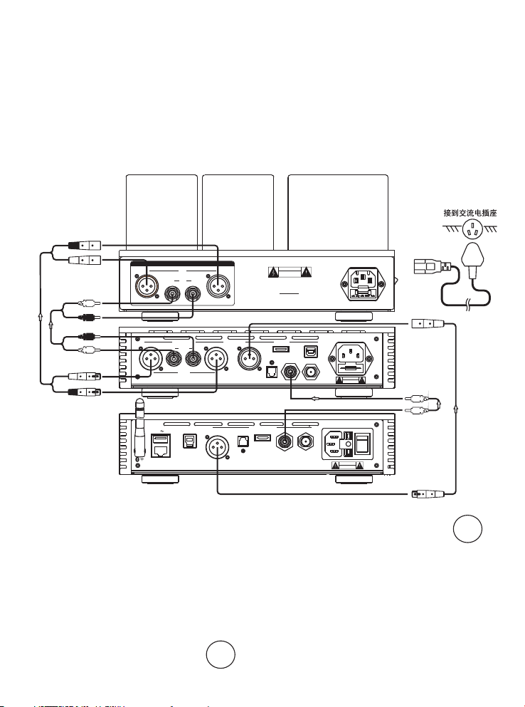
●设备连接 ------------------------------------------------------------------------------
此处是用标准方式,将主要器材连接Cayin HA-2A的方法说明。
一、音频连接:
1. 须参照将要连接的器材附带说明书;
2. 红色连接端(R标记)用于右声道;黑色连接端(L标记)用于左声道;
3. 请勿将音频线与电源线绑在一起,否则可能会对音质产生不良影响。
二、交流电源线的连接:
连接好音源后,接通本机交流电源线。
电源插座及电源开关周围应保持适当的空间,以确保可以方便操作。
到HA-2A
耳机放大器
L
到音频输出端
R
R
L
L
R
R
L
SOURCE S
XLR
R L
RCA
R L
1:G 2:+ 3:- 1:G 2:+ 3: -
ANALOG OU T
R L
RCA A( )
G
1:
+
2:
-
3:
R L
XLR B( )
珠海 斯 巴 克 电 子 设 备 有 限 公 司
ZHUHAI SPARK ELEC TRONIC EQ UIPMEN T CO., LTD.
SS
USB-PC
名称:音频解码 器
AES/EBU CO AXIAL 1COAXIAL 2OPTICAL
1:
2:
3:
G
+
-
型号:iDAC-8
名称 :
型号 :HA 2 A -
编号 :
珠 海 斯 巴 克 电 子 设 备 有 限 公 司 制 造
ZHUHAI SPARK E LECTR ONIC EQ UIPME NT CO., LTD .
AES/EBU
OPTICAL
编号:
DIGITAL OUT PUT
2
IS /DSD
警 告
内部有高压
用户请勿打开机箱
真空管耳机功 率放大器
DIGITAL IN
~220V 50 Hz 60W
T500 AL25 0Vm
~220V 50H z 35W
2
IS /DSD
T0.5AL2 50V
USB
COAXIALCOAXIAL
警告
内部有高压
用户请勿打开机箱
~220V 50H z 30W
T0.5AL2 50V
HA- 2A
iDA C-8
LAN
珠海 斯 巴 克 电 子 设 备 有 限 公 司
ZHUHAI SPARK ELEC TRONIC E QUIPMEN T CO., LTD.
名称:数字音频 播放器
三:平衡插座:
1. 本装置的平衡插座配有专业设备的XLR插座。
其性能如下所示。
型号:iDAP-8
警告
内部有高压
编号:
用户请勿打开机箱
b. 欧洲系统:①PIN1:GND
②PIN2:COLD
③PIN3:HOT
iDA P-8
COL D
GND
①
②
③
HOT
◆音乐信号作为平衡信号传输,不受外部干扰
的影响。 3. 本机采用a美国系统
◆专业的XLR连接器,提高了连接的可靠性。 当使用XLR连接器的电缆连接采用欧洲系统的前置
2. 在下列两种系统中,专业的XLR连接器在内部 放大器时,复原的信号是反相。此时,请设置使用
接线。 正确相位。
a.美国系统:①PIN1:GND
②PIN2:HOT
③PIN3:COLD
②
③
COL D
GNDHOT
①
7
Page 10

●耳机连接 ------------------------------------------------------------------------------
使用6.35mm非平 衡耳机
请将耳机的6.35 mm插头 插入到前面板的
(PHONES)拨 到STD档 ,再
旋转音量控制旋钮( VOLUME ),将音 量调整至合适位置,便可乐享醉 人的音乐。
使用4.4mm平衡耳 机
请将耳机的4.4m m插头插 入到前面板的4.4平衡耳机输出插 座(4. 4 BAL.)上,
关(PHONES)拨 到 档 ,再
档位。旋转音量控 制旋钮( VOLUME ),将音量调整至合适位置,便可 乐享醉人的音乐。
使用4PIN平衡耳机
请将耳机的4PIN插 头插入 到前面板的4PIN平衡耳机输出插 座(4P IN BAL.)上,
开关(PHONES )拨到 档,再
配的档位。旋转音 量控制 旋钮(VOLU ME),将音量调整至合适位置, 便可乐享醉人的音乐。
根据使用耳机的阻 抗,将 耳机阻抗选择(IMPEDANCE)拨到 匹配的 档位。
4.4 BAL. 根据使用耳机的阻抗,将 耳机阻 抗选择(IMPEDANCE)拨到匹配的
4PIN BAL. 根据使用耳机的阻抗, 将耳机阻抗选择(IMPEDANCE)拨到匹
注意: 切换耳机时,请将音 量调至最小位置。
非平衡耳机输出插 座(ST D)上,并将耳机输出选择开关
并将耳机输出选择 开
并将耳机输出选择
8
Page 11

●开机 ----------------------------------------------------------------------------------
开机前请再次确认各种连接正确,供电电压是否正常。
◆ 开启电源开关,VU电平表背光源亮。
◆ 延时(约60秒)后,音量旋钮指示灯亮,表示本机已经正常工作。若音量旋钮指示灯一直熄灭,表示
机器内部存在故障,请立刻关掉电源,与经销商或本公司联系。
◆ 你的音源正常工作后,通过选择正确的音源通道,调节音量控制旋钮至合适音量,你就可以享受到高质
量的音乐了。
注意:
◆ 在每次关闭电源开关后,应间隔2分钟才能开启电源开关 。
◆ 在您的音响系统工作时,切勿插拔信号线,以免损坏本机和其他设备。
,以免损坏本机和其他设备
●机器保养 ------------------------------------------------------------------------------
阅读说明书——使用电器前,请仔细阅读安全操作提示与产品说明书,以保证安全及正确操作。
保存说明书——请保存好安全操作提示与产品使用说明书,以便将来查阅。
—
警告标志 —请注意不要将产品编号撕掉或擦掉。
操作步骤——请严格按使用说明书的操作步骤或使用步骤进行操作。
使用配件——使用非本产品制造商提供的附件时(如电源线、保险管等),必须符合产品的安全要求,
否则在使用不当时可能会造成危险。
放置——请勿将本产品放置在不平坦的推车、货架、三脚架、挂墙架或简易书架上,产品有可能因此倒
下来砸伤小孩或大人,产品也会被摔坏。
电源——本产品只能使用本身标示的交流电电源类型,如果你不清楚家中的电源类型,请与经销商或供
电部门联系。
线路负载过量——给本产品供电的电源插座同时连接其它电器时,请注意负载不要过量,否则可能造成
火灾或电击。
维修服务——请勿随意拆开机器调整内部元件参数,以防触电。
故障排除——如果您在使用产品过程中遇到问题,可以按第10页《一般故障处理》方法分析或排除故障
●保修 ----------------------------------------------------------------------------------
1. 整机保修一年(真空管保修半年)。
2. 为使保修生效,客户必须在购买本机十日内将填好的保修卡交于经销商或寄回珠海斯巴克电子设备有
限公司。
3. 在责任期限内,本公司保证产品在正常使用下出现的质量问题的维修,条件是该产品得到返修许可并
运到保修单位或运回珠海斯巴克电子设备有限公司。
4. 如果没有得到本公司允许私自打开机器,保修承诺失效。
注:本说明书中的信息如有更改,恕不另行通知。
9
Page 12

故障现象
可能的原因
解决方法
开
机
无
声
VU电平表
背光源不亮
电源线未连接
检查供电电路及电源线
主保险管已断
更换相同规格的保险
VU电平表
背光源亮
无信号输入
检查音源是否正常
检查本机音源输入选择是否正确
音量电位器在最小位置
调整音量旋钮到合适位置
信号线没有连接好
重新连接信号线
耳机插头没有连接 好
确保耳机插头可靠 连接
耳机输出选择开关 选择错 误
确认耳机输出选择 开关是 否正确
音源输入选择开关 选择错 误
确认音源输入选择 开关是 否正确
噪音过大
输入信号线地线开路或接触不良
更换或重新连接信号线
机器内部故障
请与经销商或保修单位联系
音场定位感不好
信号输入的声道接反
耳机输出线的声道接反
按要求重新接线
●一般故障处理---------------------------------------------------------------------------
为了使设备能维持其卓越性能,请注意做好保养和正确操作。不正确的操作会导致误认为故障,如
果本装置有问题请检查下列事项。有时候问题可能出在其他设备上,请检查其他设备以及有关的连接线
路,如果故障未被消除,请与斯巴克公司经销商或销售部联系。
保 修
10
Page 13
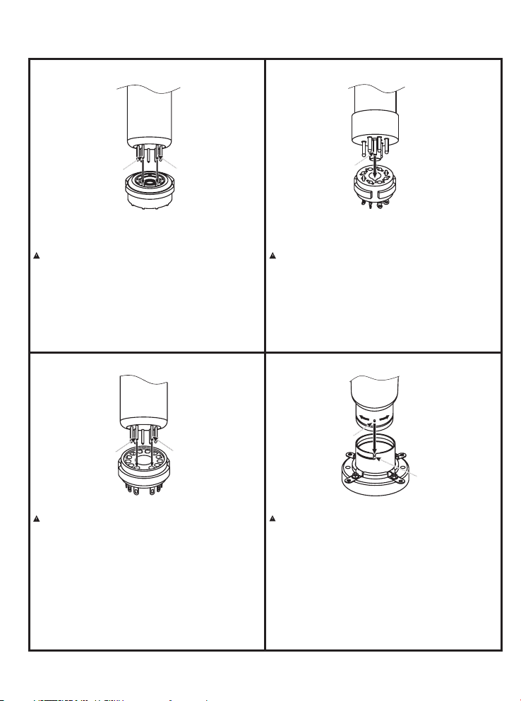
●真空管安装示意图----------------------------------------------------------------------
小九脚真空管安装示意图 八脚真空管安装示意图
9脚
适用真空管:1 2AU7(EC C82) 12AX7(E CC83)、 、
ECF82、6U 8、12B H7、12AT7(E CC81 )、
6922(ECC88)等小 九脚真 空管。
请注意
安装小九脚真 空管时 ,注意真空管的 针脚与 管座
的针孔对齐, 否则插 错将使机器无法 正常工 作,
引起真空管损 坏,严 重时可能导致机 器故障 。
正确换插真空 管的方 法:
安装小九脚真 空管时 ,将真空管的针 脚与管 座的针孔对
齐,上下垂直 拔插安 装(如上图所示 )。
1脚
十二脚真空管安装示意图 大四脚真空管安装示意图
12脚
适用真空管:1 7BF 11、17BF11A等十二 脚真空 管。
请注意
安装十二脚真 空管时 ,注意真空管的 针脚与 管座
的针孔对齐, 否则插 错将使机器无法 正常工 作,
引起真空管损 坏,严 重时可能导致机 器故障 。
正确换插真空 管的方 法:
安装十二脚真 空管时 ,将真空管的针 脚与管 座的针孔对
齐,上下垂直 拔插安 装(如上图所示 )。
1脚
定位销
适用真空管:K T15 0、KT170、KT8 8、655 0、EL34、
6V6、6SN7、6 SL7、5 AR4、17AX4 GT等
八脚真空管。
请注意
安装八脚真空 管时, 注意真空管的定 位销与 管座的定
位孔对齐,否 则插错 将使机器无法正 常工作 ,引起真
空管损坏,严 重时可 能导致机器故障 。
正确换插真空 管的方 法:
安装八脚真空 管时, 将真空管的定位 销凸台 与管座定位孔
的凹槽对齐, 上下垂 直拔插安装(如 上图所 示)。
定位销
卡槽
适用真空管:8 45、80 5、211等大四脚真 空管。
请注意
安装大四脚真 空管时 ,将真空管定位 销与管 座卡槽对齐,
再顺时针方向 旋转45° 卡紧。定位销脱 落或缺 失时,严禁
安装真空管。 否则插 错管脚将使机器 无法正 常工作,严重
时可能导致机 器故障 。
正确安装真空 管的方 法:
安装大四脚真 空管时 ,将真空管定位 销与管 座卡槽对齐放
入,再顺时针 旋转45° 卡紧。(如上图 所示) 。
取出大四脚真 空管时 ,将真空管逆时 针旋转4 5°,松动后
向上取出。
11
Page 14

Page 15
HA-2A HEADPHONE AMPLIFIER
4.4 BAL.
LM H
4PIN BAL .STD
IMPEDA NCEPHONES
4.4 BAL .
STD
4PIN BAL .
XLR RCA
SOURCE S
VOLUM E
MIN MAX
HEADPH ONE AMP LIFIE R HA- 2A
User's Manual
Page 16

Thank you for choosing Cayin HA-2A Headphone Amplifier
We have inserted protective foam inside the Vacuum Tube Cage in order to protect the
vacuum tubes during transportation. Please remove these foams before you connect the
amplifier into your sound system. Fail to do so might cause serious damage to the amplifier
or disaster such as fire accident.
We have prepared this user manual to help you understand the features and get familiar
with the operation of the amplifier. We suggest all customers read through this manual
before they start to use the device.
Table of Contents
Table of Contents ……………………………………………………………
Package Contents ……………………………………………………………………………
Product Features …………………………………………………………………………...
Specifications ……………………………………………………………………………….
Safety Precautions ……………………………………………………………………………
Front Panel Functional Description ……………………………………………………….
Rear Panel Functional Description ………… …………………………………………….
Top Panel Functional Description ………………………………………………………...
Installation …………………………………………………………………………………...
Vacuum Tube Substitution ………………………………………………………………...
Connect to Audio Equipment ………………………………………………………………...
Connect to Headphones ……………………………………………………………………...
Basic Operation ……………………………………………………………………………….
Warranty Service
Maintenance ………………………………………………………………………………...
Troubleshooting …… ……………………………………………………………………….
How to Install Vacuum Tubes…………………………………………………………………
………………
……………………………………………………………………………
12
13
14
15
16
17
18
19
20
20
21
22
23
24
24
25
26
12
Page 17

Notice:
This amplifier is designed, optimized and manufactured by factory designated components.
Cayin reserves the right to void the warranty of the product in case of unauthorized repair,
modification or change to the product, and we shall not responsible to any failure or damage
caused by replacement of non-designated components.
● Package Contents -----------------------------------------------------------------
Please place the box in upright position according to the marking of the package. Please
examine the product package before you open it, the package should be free from any
physical damage or water stain. You should find the following items when you open the
package:
1.Cayin HA-2A x1
2.User's Manual x1
3.AC Power Cord x1
4.Spare Fuses x2 (~220V-240V:T500mAL250V; ~100V-120V:T1AL250V )
Recommendation
Please keep all packaging materials for future use as you may need to repackage the
amplifier in the future. Please fill in the product warranty card immediately and mail it to
authorized dealer to safeguard your after-sales service.
Note: Please make sure the AC voltage of your local power supply match the voltage
information printed on the back panel before you power up the amplifier. Incorrect input
voltage setting will cause damage to the machine or might even lead to serious household
accident. Cayin reserves the right to refuse service or responsibility on related instances. If
the marked voltage is different from your local power supply voltage, please contact your
authorized dealer or Zhuhai Spark Electronic Equipment Co., Ltd.
Attention: the product package should include only the items in the list above.
13
Page 18

● Product Features -----------------------------------------------------------------
Point t o point w iring with p remium gra de of wir es. The enti re circ uitry is han d-wired
◆
by skil lful cr aftsman.
◆ Mat ched-pai r custom bui ld EI out put transf ormer s.
Custo m build E I power tran sformer.
◆
◆ 17A X4GT from RCA are use d as Tube Re ctifier pr oviding st able an d clean powe r
suppl y to the Vol tage Amplif ication St age.
◆ Mul ti-stage i ndepende nt powe r supply vol tage am plificat ion employ s indep endent
regul ator de sign minim um ripple ef fect of powe r interfer ence en sure outst anding
audio p erfor mance, fre e from any gra in and ha rdness.
◆ Ded icated imp lementat ion of si ngle- end ed ampl ificatio n circuit of fer simple , pure
and dev oted mu sic presen tation.
◆ All t ubes used fo r HA-2A a re NOS Tubes wi th an unique m ellow a nd warmth.
◆ Amp erex ECF82 /6U8 are use d for vol tage ampli ficat ion.
◆ Amp erex 17BF11 are us ed for po wer amplif ication.
◆ Hig h quality Ne utrik 6.35 mm sing le-ended h eadph one, NIPPO N DICS 4. 4mm
balan ced hea dphone, an d Neutrik 4- pin bal anced head phone a re include d.
◆ In -h ouse desig ned out put t ransf ormers pro vide th ree set of imp edance mat ched
outpu ts (Hig h, Mid, Low) f rom 8Ω to 600Ω at yo ur dire ction.
◆ Two se ts of line inp uts: XLR Balanced a nd RCA Singl e-end ed.
◆ Str ong output p ower to matc h with wi de range of he adpho ne in the mark et.
◆ Hig h performa nce Alps Pot entio meter offers du rable , high-pre cision Volu me
Contr ol.
◆ Sof t start func tion (abou t 60 seco nds).
◆ Spe cial shiel ding and ant i-sho ck design.
◆ Des ign with an in novative circui t layout and h ighly e ffe ctive shie lding c onsidera tion,
the com ponen ts will func tion at prem ium env ironment t o ensure hig h quali ty audio
perfo rmanc e form the amp lifier.
◆ Equ ipped with e asily-in stall ed tube cove r for pro tection.
14
Page 19

ITEM
SPECIFI CATION S
Rated
Output
STD
330mW+330mW(L);550mW+550mW(M);750mW+750mW(H)
4.4 BAL.
200mW+200mW(L);300mW+300mW(M);270mW+270mW(H)
4PIN BAL.
800mW+800mW(L);900mW+900mW(M);1000mW+1000mW(H)
Frequency Response
20Hz~50kHz ±3dB
TH+D
0.2% (1kHz, 100mW; 5% Under Rated Power)
Sensitivity
450mV~600mV
S/N Ratio
100dB(A-Weighted)
Headphone Impedance
L:8~64Ω; M:65~250Ω; H:251~600Ω
Headphone Connectors
6.35mm x1 ;4.4mm BALANCEx1; 4pin XLR x1
Input Impedance
RCA:25KΩ;XLR:10KΩ
Input Connector
RCA ;x1 x1XLR
Tube used
Amperex ECF82/6U8 A mpe rex 1 7BF 11 RCA 17AX4GT×2、 ×2、 ×1
Dimension
270mm 2 47m m 1 43mm× ×
Net Weight
10KG
Fuse
~220V-240V: ~100V-120VT500mAL250V; :T1AL250V
Power Consumption
60W
Working Condition
Temp:0℃~40℃ Humidity:20%~80%
Storage Condition
Temp:-20℃~70℃ Humidity:20%~90%
● Specifications----------------------------------------------------------------------
15
Page 20
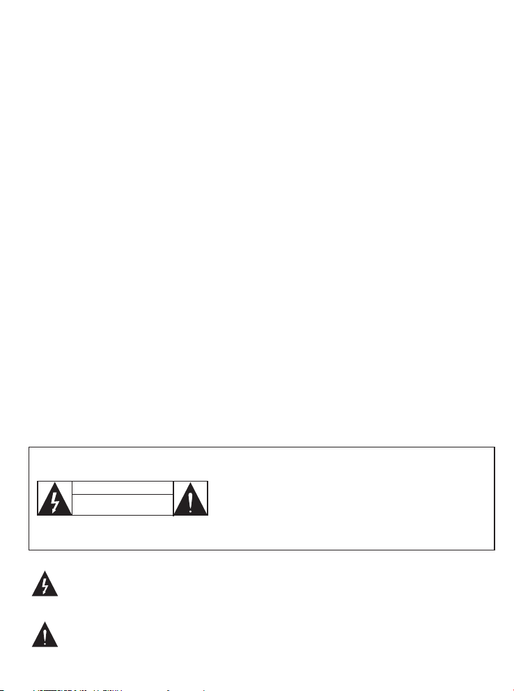
● Safety precautions-----------------------------------------------------------------
1. Un plug the pow er cord if you are not go ing to use th e amplifier for an exten ded
perio d of time , and keep the m achine in pr oper co ndition.
2. Tube amp lifier w ill buil t-up its operati on tempe ratur e after long hou rs of op eration.
Pleas e keep the am plifier at a well-ven tilat ed env ironment and do not co ver th e
ampli fier o r bloc ked the vents. P oor ve ntilatio n will l ead to e xcessive ly high
opera tion te mperatur e and can caus e malfu nction or fi re.
3. To av oid da magin g the amplif ier, you must co nnect a source de vice to the input
termi nals be fore you sel ect that as th e activ e input of you r HA-2A.
4. To avoid d amaging the amplifi er, shor t ci rcuit a mong th e ou tput te rmina ls are strictl y
forbi dden.
5. Do not attempt to servi ce thi s prod uct yo ursel f. Ope ning t he cover may ex pose y ou
to elec tric sh ock or other h azards.
6. Do not attemp t to disassemb le the machine . Ca yin res erves the right to void the
warra nty of the pr oduct in case of u nauth orized repair, modifica tion or c hange t o the
produ ct. All ser vice an d maint enanc e must be con ducte d by author ized se rvice
techn ician .
7. Th e am plifier must be keep awa y fr om w ater drippin g or wat er s plitting , do not pla ce
any obj ects fi lled
with li quids s uch as vases o r some other s on the to p or around th e amplifie r.
8. Pl ease disco nnect p ower ca ble before y ou atte mpt to cl ean the m achin e. Please use
soft clean cloth t o wipe clean the cha ssis, d o not use volati le solu tion or corros ive to
clean p roduc t.
9. Pl ease handl e with care, a void te mpering to t he mach ine.
◆ To reduce the risk of electric shock, do not remove
the cover.
CAUTION
RISK OF E LECTRIC SHO CK
DO NOT OPE N
◆ No user serviceable parts inside. Refer servicing to
qualified service personnel.
◆ To reduce the risk of fire or electronic shock, do not
expose the unit to rain or moisture.
This symbol warns the users that uninsulated voltage within the unit may be sufficient
to cause electrical shock. It is dangerous to make any kind of contact with any part
inside the unit.
This symbol alerts the users that important information concerning the operation and
maintenance of this unit has been provided. The information should be read carefully
to avoid problems.
16
Page 21
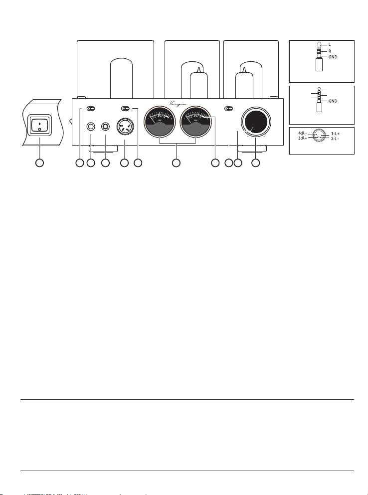
● Front Panel Functional Description ---------------------------------------------
Polarity Diagram for 6.35mm
POWER
Headphone Jack.
4.4 BAL.
ON
OFF
1
STD
2
LM H
4PIN BAL .STD
IMPEDAN CEPHONES
4.4 BAL.
4PIN BAL.
43
5
6
7
XLR RCA
8
SOURCES
VOLUME
MIN MAX
HEADPHO NE AMPL IFIER H A-2A
119 10
Polarity Diagram for 4.4mm
Balanced Headphone Jack
Polarity Diagram for 4 PIN XLR
Balanced Headphone Jack
L+
L-
R+
R-
Diagr am 1:HA-2 A Front Panel
①.Power On/Off: Turn on and off the
amplifier.
②.Headphone Output Selector: With the
switch you can select the suitable type of
headphone output. HA-2A offers three
types output.
③.STANDARD: Output for headphones
terminated in 6.35mm TRS connector
④.4.4 Balance Output:4.4 balance
output for headphone terminated in
4.4mm connector.
⑤.4PIN BALANCE: Output for headphones
terminated in 4pins XLR connector
IMPEDANCE: Select the most desirable
⑥.
impedance-matched output from the
amplifier and three options offered:
(L:8~64Ω; M:65~250Ω; H: 251~600Ω)
⑦.VU Meter: Monitor output level of the
amplifier
⑧.VU Meter Backlight Turn on the Amplifier
and the Blacklight will light up.
:
⑨.SOURCES: Select Balanced or Single-
ended Input
⑩.Volume Level Indicator (Operation
Indicator):Used to indicate the volume
position. Once powered on the indicator will
light up after soft-start of 60 seconds.
⑪ Volume Knob
.
Used to control volume
Attention:
If your want to connect a 3.5mm terminated headphone to the amplifier, you need a 3.5mm to 6.3mm
◆
adapter (not included in the package).
◆Listening through headphones at a high volume for extended periods of time can result in hearing
impairments.
◆Please do not use mono (TS) phone plug with this amplifier as this might cause serious
damage such as short circuit in the amplifier.
◆Please unplug the power plug from AC power circuit if the amplifier is not used for a long time
17
Page 22
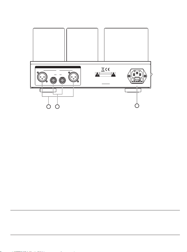
● Rear Panel Functional Description ----------------------------------------------
AC INPU T
~230V 5 0Hz 60W
T500 AL250 Vm
3
1:G 2:+ 3: - 1:G 2 :+ 3:-
Balanced input (XLR)
①.
SOURC ES
XLR
R L
RCA
R L
1 2
Diagr am 2: HA- 2A Rear Pane l
CAUTION
RISK OF ELECTRIC SHOCK
DO NOT OPEN
HEADPHO NE AMPLI FIER
MODEL : HA 2A-
SER.N O.:
ZHUHAI SPA RK ELECT RONIC E QUIPM ENT CO. , LTD.
Connect a balanced audio input to the amplifier. Please make sure the left and right
channel is connected correctly
②.Single-ended input (RCA)
Connect a single-ended audio input to the amplifier. Please make sure the left and right
channel is connected correctly
③.AC Power Input with Fuse Holder: please replace fuse with the same specification
Attention:
Please make sure the AC voltage of your local power supply match the voltage of the
amplifier. Cayin will not be responsible for the damage or accidents such as fire
caused by incorrect input voltage
18
Page 23
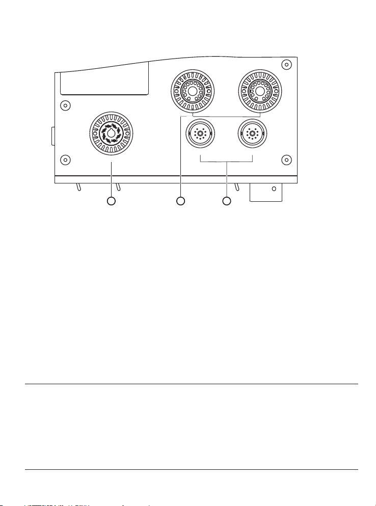
● Top Panel Functional Description -----------------------------------------------
V3
17BF11
V1
17AX4G T
V5
ECF82/ 6U8
21 3
Diagr am 3: HA- 2A Top Pane l
.
① V5: RCA 17AX4GT Vacuum TUBE
.
② V3、V4: Amperex 17BF11 Vacuum TUBE
. ECF82/6U8
③ V1、V2: Amperex Vacuum TUBE
ECF82/ 6U8
V4
17BF11
V2
Attenti on:
The vacuum tube will become very hot during operation, please be careful and don’t get
◆
burned.
Please turn off the amplifier for 20 minutes before replacing the vacuum tube. Hold the
◆
base of vacuum tube firmly and to avoid damaging the fragile part of the vacuum tube.
When install vacuum tube to the amplifier, position the vacuum tube correctly according
◆
to the alignment pin before push the vacuum tube base into the socket.
19
Page 24
● Installation -------------------------------------------------------------------------
Please make sure all associated equipment are in perfect working condition before you
install the amplifier
Please pay attention to the following details when you install the amplifier.
◆Do not place the power amplifier under direct sunlight or near other heat sources.
◆To prevent the amplifier from overheating, please keep the amplifier at a well-ventilated
environment and do not cover the amplifier or blocked the vents.
◆Avoid moisture, keep the amplifier from dust if possible.
◆Make sure the amplifier are setup at a location that can be connected to the AC power
supply and other audio equipment conveniently.
◆Place the amplifier at a flat surface, make sure all four supporting tips are evenly loaded.
◆Please keep amplifier not less than 15cm away from and the wall.
● Vacuum Tube Substitution--------------------------------------------------------
Vacuum Tube
Amperex ECF82/6U8
Amperex 17BF11
RCA 17AX4GT
ECF82、6U8
17BF11A
17AX4GTA
20
Substit ution
Page 25
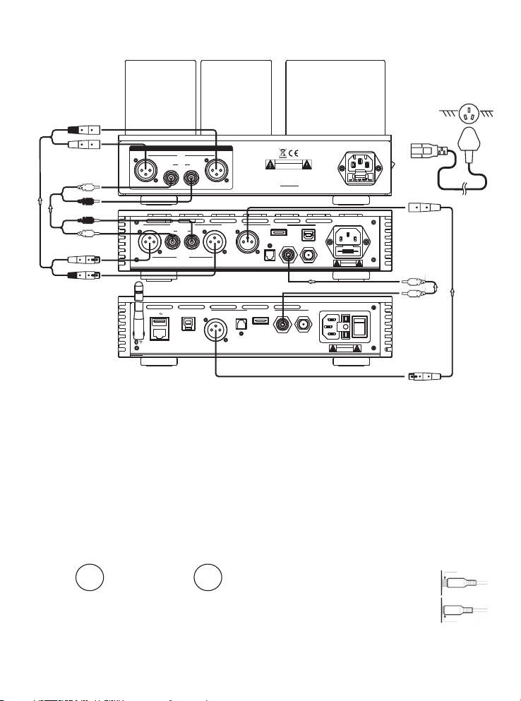
● Connect to Audio Equipment ----------------------------------------------------
This section will illustrate how to connect audio equipment to the HA-2A amplifier.
Conne ct to the
Conne ct to HA-2A
Headp hone Amplif ier.
Analo g Output.
L
R
R
L
L
R
Conne ct to
R
L
SOURCE S
XLR
R L
RCA
R L
1:G 2:+ 3:- 1:G 2:+ 3: -
ANALOG OU T
R L
RCA(A)
G
1:
+
2:
-
3:
R L
XLR(B)
ZHUHAI SPARK E LECTR ONIC EQ UIPME NT CO., LT D.
SS
AUDIO D/A CO NVERTE R
USB-PC
G
1:
+
2:
-
3:
MODEL: iDAC- 8
AES/EBU CO AXIAL 1COAXIAL 2OPTICAL
HEADPHON E AMPLIF IER
MODEL: H A 2 A-
SER.NO .:
ZHUHAI SPARK E LECTR ONIC EQ UIPME NT CO., LTD .
AES/EBU
OPTICAL
SER.NO.:
DIGITAL OUT PUT
2
IS /DSD
CAUTION
RISK OF ELECTRIC SHOCK
DO NOT OPEN
DIGITAL IN
2
IS /DSD
AC INPUT
~230V 50 Hz 60W
T500 AL25 0Vm
~230V 50/ 60Hz 35 W
T0.5AL2 50V
USB
COAXIAL 1COAX IAL 2
CAUTION
RISK OF ELECTRIC SHOCK
DO NOT OPEN
~230V 50/ 60Hz 20 W
T0.5AL2 50V
HA- 2A
iDA C-8
Power S ocket.
LAN
ZHUHAI SPARK E LECTR ONIC EQ UIPME NT CO., LT D.
DIGITAL AUDIO P LAYER
MODEL: iDAP- 8
SER.NO.:
BALANCE Socket:
1. The BALANCE socket is with XLR input. The
functions are following:
◆
Music signal is transferred as balance signal
without the outside disturbance.
◆
Professional XLR connectors are used to raise
reliability of connection.
2.
In the following two systems, professional XLR
connectors are used for inside connection.
USA System
a. :
①PIN1:GND;
②PIN2:HOT;
③PIN3:COLD
HOT
3. This amplifier uses the USA System.
②
③
COL D
GND
①
European System
b. :
①PIN1:GND;
②PIN2:COLD;
③PIN3:HOT
COL D
GND
①
②
③
HOT
If the XLR balance connector is used by
European system, the restored signal of
pre-amplifier or main amplifier will be
inverse. Therefore, please setup the correct
phase in advance.
21
CAUTION
RISK OF ELECTRIC SHOCK
DO NOT OPEN
iDA P-8
Atten tio n to Audio C onn ect ion:
1. Ple ase refer to the ma nua l of associated
equip men t whenever nece ssa ry.
2. Do no t connect the pow er co rd until all
equip men t are properly co nne cted
3. “R” in dic ates the right ch ann el;
“L” ind ica tes left channe l.
4. Ple ase make sure all c onn ectors are
secur ely i nstalled. Bad c onn ection
might c aus e noise and degra de in a udio
perfo rma nce, or even dama gin g your
equip men t.
5. Ple ase do not tie the po wer c ord, audio
inter con nects, and spea ker
Wrong connection
cable t oge ther or run them in
paral lel b ecause this wil l
produ ce ad verse effect on
audio p erf ormance.
Right connection
Note: P lea se make sure + and -, l eft a nd
right a re co nne cted prope rly.
Page 26
● Connect to Headphones ----------------------------------------------------------
Selec ting He adphone Co nnection
HA-2A pr ovide d three type s of headpho ne outp ut: 4-pins X LR for balan ced, 4. 4mm
Balan ced ,6. 35mm for sin gled-end , we have o ptimized t he headpho ne ampl ifier to
perfo rm sati sfactory f or all outpu ts, use r are free to us e any headph one out put
accor ding to t heir need wi thout worr ying on e is better th an the other.
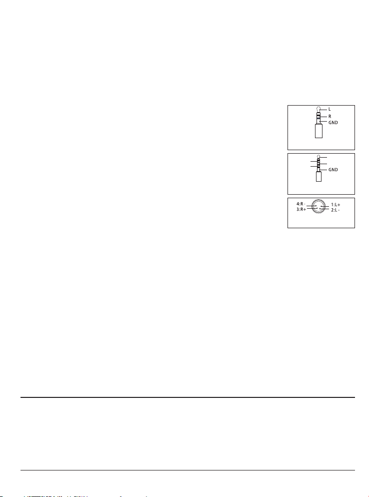
Singl e-end ed He adpho ne Connect ion
HA-2A pr ovide s one set of 6.3 5mm headph one out put,
the pin d efini tion of the he adphone co nnect or is as illus trated.
Headp hones t erminate d with 3.5mm c onnec tor will req uire a 3.5mm
to 6.35 mm adap ter in order t o use it with th is head phone ampl ifier.
4.4mm B alanc ed Headpho ne Connect ion
HA-2A pr ovide s one set of 4.4 mm headpho ne outp ut, the pin
defin ition o f the headph one connec tor is as i llustrat ed.
Headp hones t erminate d with 2.5mm c onnec tor will req uire a 2.5mm
Polarity Diagram for 6.35mm
Headphone Jack.
Polarity Diagram for 4.4mm
Balanced Headphone Jack
L+
L-
R+
R-
to 4.4m m adapt er in order to u se it with thi s headp hone ampli fier.
XLR Bal ance He adphone Co nnection s
HA-2A pr ovide o ne set of 4-pi n XLR headph one out put, the pin
Polarity Diagram for 4 PIN XLR
Balanced Headphone Jack
defin ition o f the XLR conn ector is as il lustr ated.
Headp hones t erminate d with dual XL R (3-pi ns), 4.4mm o r 2.5mm
balan ced hea dphone con nectors wi ll requ ire corres ponding XL R4
adapt er in ord er to use it wit h this headp hone am plifier.
IMPED ANCE ma tched outp ut
Headp hones a re current ly availab le from 8 Ω to 600Ω, in vi ew of this wid e range o f
imped ance ra ting, HA-2 A provides th ree set s of impedan ce matched o utput s
(L:8~ 64Ω; M: 65~ 250Ω; H : 251~600Ω ) to ensu re the headp hone ampli fier ca n handle
vast va riety o f headphon es satisfa ctory.
We recomme nd user s to start wit h the output s ettin g that match t he impedan ce rati ng
of your h eadph one.
It is tec hnica lly safe to se lect any imp edanc e setting fo r your headp hone. You c an try
other i mpeda nce settin g without wo rryin g causing an y damage to yo ur head phone.
Attention:
Balan ced hea dphones ca n convert in to sing le-ended h eadphone w ith app ropriate
◆
conve rter an d use the 6.35 mm headpho ne outp ut.
◆Singl e-end ed headpho ne cannot us e an adap ter to plug in to the XLR4 ba lance d
headp hone ou tput of the HA -2A, it can ca use dam age to your he adphone an d/or
headp hone am plifier.
◆Tur ning the vol ume to th e minimum wh en you ex change the H eadphone .
22
Page 27

Attention:
◆Connect power cord after all equipments are well connected.
◆It is normal that the transformers will emit heat when the amplifier is used for long hours
◆Please unplug the power plug if you won’t use the amplifier for a long time
● Basic Operation ---------------------------------------------------------------------
Please make sure all connections are correct and power supply voltage is stable before turn
on the amplifier.
1. Turn on the Amplifier and the VU Meter will light up.
2. In about 60 seconds after the soft-start the Volume Level Indicator will light up steadily and
then the Amplifier is ready for operation. If the Volume Level Indicator does not light up the
Amplifier is malfunction. Please turn off the amplifier and contact your local dealer for
service support.
3. The tubes regulated power supply might require around 30-60 seconds to ramp up the
voltage gradually, it is normal if you heard ting-ting noise from your headphone or speaker
during this time.
4. The vacuum tube might require 10 minutes of warm up before they reach optimum
performance.
5. Select your input source: XLR for balanced input, RCA for single-ended input.
6. If you are using single-ended headphone, insert the 6.35mm connector of your headphone
into the STANDARD headphone output on the front panel. Switch the headphone output
selector (PHONES) to STD.
7. If you are using a 4.4mm balanced headphone, insert the 4.4 connector of your headphone
into the 4.4 BALANCE headphone output on the front panel. Switch the headphone output
selector (PHONES) to 4.4 BAL.
8. If you are using a 4pin XLR balanced headphone, insert the XLR4 connector of your
headphone into the 4 PIN BALANCE headphone output on the front panel. Switch the
headphone output selector (PHONES) to 4 PIN BAL.
9. Select the appropriate output (L, M, or H) on the IMPEDANCE switch according to the
specification of your headphone for optimized performance.
10. Adjust Volume to appropriate level and enjoy your music.
Attention:
Pleas e do not di sconnect y our interc onnec t when the amp lifier is op erati ng, this
◆
might c ause da mage to the am plifier or a ssoci ated equip ment
◆You ca n swap he adp hones d uring play back, b ut to avoid da maging you r sensi tive
headp hone an d protect yo ur hearing , pleas e turn the vol ume down to 0 wh en you
unplu g or plug i n another pa ir of headph one.
◆If you ha ve turn o ff th e amplifie r, please wai t 2 minut es before yo u turn it on aga in,
ot it mig ht caus e damage to th e vacuum tub es.
23
Page 28

● Warranty Service--------------------------------------------------------------------
1.The Product is warranted for a period of twelve (12) months from the date of original
purchase (the “Warranty Period”). Replacement Products are warranted for the
remainder of the original twelve (12) month warranty period. Six-month warranty on
stock vacuum tubes.
2.The defective product must be returned to our authorized agent or Zhuhai Spark
Electronic Equipment Co., Ltd (the “Company”) for service. You must receive approval
from our authorized dealer or the “Company” before you send out the defective product.
3.Do not attempt to disassemble the machine without prior approval of the “Company”
otherwise we reserves the right to void the warranty of the product
● Maintenance ------------------------------------------------------------------------
Read the Manual: to operate the amplifier correctly, please read this user's manual carefully
to understand product features and safety precaution .
Keep the Manual: Please keep this manual properly for future reference.
Signage: Do not tear off or rub away the serial number.
Operation: Please follow the operations in this manual strictly.
Accessories: If you are going to use non-factory supplied accessories such as power cord
or fuse, please make sure they are fully compatible with the safety requirements otherwise
might cause damage due to improper usage.
Placement: The amplifier is heavy and the vacuum tubes are fragile, please place the
amplifier on a stable, flat surface, preferably a strong cabinet or rack. If the amplifier falls
down because of insecure placement, the amplifier will suffer damage and possibly causing
serious household accident.
Power Supply: Please make sure your household AC power supply matches the power
requirement of your amplifier. If you are uncertain about the power supply situation, please
contact your authorized dealer or local power supply institutions.
Overloading: If you have to connect the amplifier to a power stripe or multi-socket, please
make sure the loading is within safety consideration. Overloaded power connection might
lead to electric shock or fire accident.
Warranty Service: Do not attempt to disassemble the machine or modify the component,
this will void the warranty service and might exposure yourself to electric shock.
Troubleshooting: If you encounter any abnormal behavior during setup or playback, please
refer to the advices in next pages of this manual to recover your amplifier back to normal
operation. If you fail to rectify the problems after that, please contact your authorized dealer
for technical support.
24
Page 29
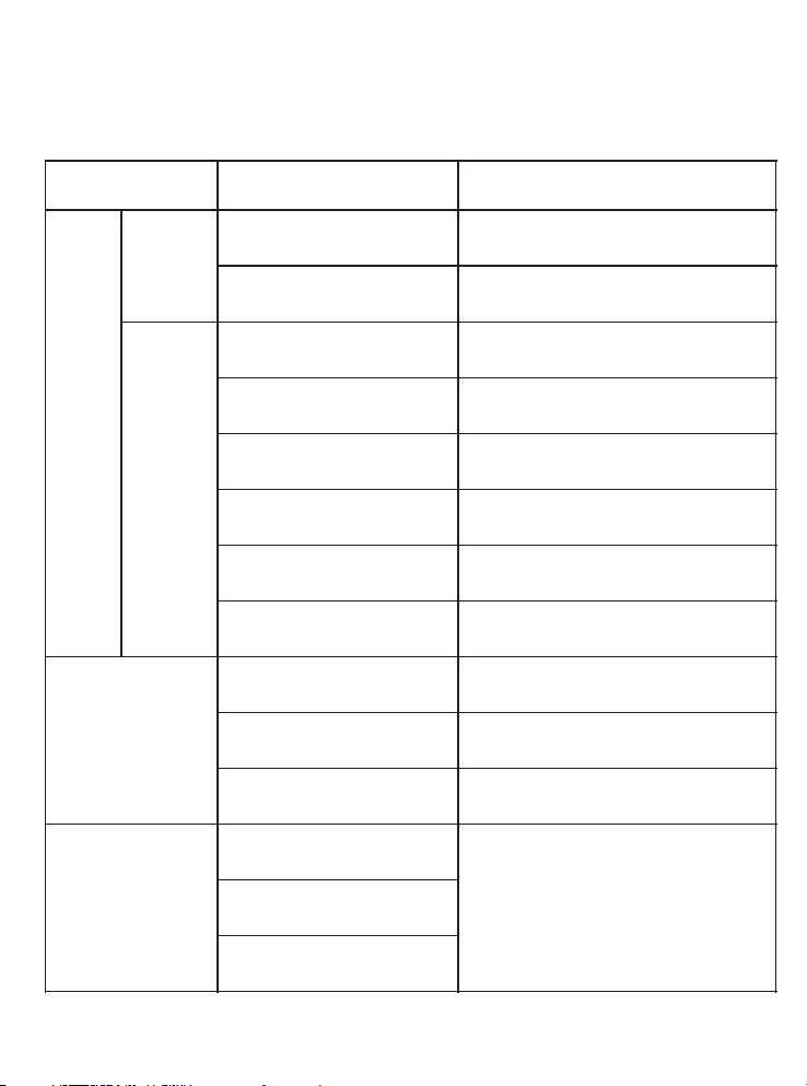
Problem
Cause
Solutio n
No
Sound
after
power
on
VU Meter
does not
light up.
Power i s not c onnected
Conne ct th e power cord secu rel y.
Check t he ma in power supply.
Main fu se is o ut.
Repla ce fu se with same spec ifi cation
VU Mete r
light s up.
NO inpu t sig nal .
Check s our ce equipment is w ork ing
Selec t inp ut source corre ctl y
Volume a t min imum position
Tur n up vo lume
Inter con nect not proper ly
conne cte d
Conne ct al l cables secure ly
Headp hon e cable not
prope rly c onnected
Conne ct he adphone cable p rop erly
Headp hon e output not
speci fie d correctly
Selec t hea dphone output c orr ectly
Sourc e Sel ector wrong
Selec ted
Selec t the c orrect Source I npu t.
Exces siv e noise
Input s our ce wrongly
conne cte d
Insta ll in terconnect pr ope rly
Inter con nect groundin g
disco nne cted
Repla ce in terconnect
Equip men t malfunction
Conta ct au thorized deal er fo r
techn ica l support
Sound sta ge and
imagi ng no t focused
Left an d rig ht channel of
sourc e equ ipment revers ed
Reins tal l related cable d cor rectly
Headp hon e cable polarit y
rever sed
Speak er ca ble polarity
reser ved
● --------------------------------------------------------------------Troubleshooting
Please follow the instruction in the manual in order to keep the amplifier under proper
working condition. If the amplifier is not functioning as intended, please check according
to following tip to look for the possible reason.
25
Page 30
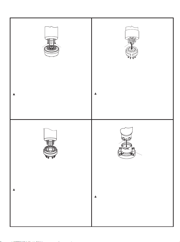
● -----------------------------------------------------How to Install Vacuum Tubes
How to Ins tal l 9-P in Vacuum Tub es
Pin N o. 9
Applicable vacuum tube:
12AU7(ECC82)、12AX7(ECC83)、ECF82、6U8、12BH7、
12AT7(ECC81)、6922(ECC88) etc. 9-Pin vacuum tubes.
Ins truct ions to Chang e and In stall the vac uum tu bes:
To ins tall a nin e-pin vacuum tub e, al ign t he pi ns of the
Pin N o.1
vac uum tub e with th e hole s of the tu be sock et and
ins ert th e tub e vert ical ly up and do wn (as show n in t he
fig ure abo ve).
Please not e th at when ins tal ling the nine-p in
vacuum tu be, pa y atte nti on to the align ment of the
vacuum tub e pins wit h the hole s of the tub e s ock et.
Oth erw ise wrong ins erti on will cau se dam age to the
vacuum tub e a nd prev ent the ampl ifi er from wor king
proper ly, whi ch ma y lead t o fai lure o f the a mpli fie r.
How to Ins tal l 12- Pin Vacuum Tu bes
Pin N o. 12 Pin N o.1
Applicable vacuum tube: 17BF11、17BF11A etc. 12-Pin
vacuum tubes.
Ins truct ions to Chang e and In stall the vac uum tu bes:
To install a twel ve-pi n vac uum tu be, a lign t he pi ns of the
vac uum tu be wit h the holes of the tube socke t and i nsert
the tube verti cally up and down (as shown in the figu re
abo ve).
Ple ase no te that wh en in sta llin g th e twe lve- pin
vac uum t ube, pay att enti on to t he a lign ment o f th e
vac uum tub e pins with t he hol es of th e tube s ocke t.
Oth erwis e wron g ins erti on wi ll cau se dam age t o the
vac uum tub e and p reve nt the a mpl ifie r from w ork ing
pro perly, w hich m ay lead t o failu re of the a mplifier.
How to Ins tal l 8-P in Vacuum Tub es
Pos ition ing Pin
App licab le vacu um tube :
KT1 50、KT17 0、KT88、65 50、EL34、6 V6、6SN7、
6SL 7、5AR4、17 AX4GT , etc. 8- pin vac uum tub es.
Ins truct ions to Chang e and In stall the vac uum tu bes:
To inst all an eigh t-pin vacuu m tub e, ali gn the posi tioni ng
pin of th e tu be wi th t he g roove s in the p ositi oning holes
of t he tu be so cket, and in stall the t ube b y pul ling up and
dow n verti cally ( as show n in the fi gure a bove) .
Ple ase no te t hat w hen i nst alli ng th e ei ght- pin v acu um
tub e, pay att enti on to the alig nmen t of th e va cuum tube
pos ition ing pi n wit h the p osit ion ing h ole o f the t ube
soc ket. O ther wise wron g ins erti on wi ll cau se da mage to
the vacu um tu be an d prev ent t he am plif ier f rom wo rking
pro perly, w hich m ay lead t o failu re of the a mplif ier.
How to Ins tal l Big 4 -Pin Vacuu m Tube s
Pos ition ing Pin
Pos ition ing Pin S lot
App licab le vacu um tube : 845、805、2 11 etc . 4-p in
vac uum tub es.
Ins truct ions to C hange a nd Inst all th e vacuu m tubes :
To i nsta ll th e b ig fo ur-p in vac uum tube, al ign t he
vac uum tube posi tion ing pin with posi tion ing pin slot of
the tube s ocke t and t hen ro tate 4 5° cl ockw ise to t ight en.
(As s hown i n the pic ture a bove ). To take o ut the b ig fou rpin v acuu m tube , turn th e tube 4 5° cou nter cloc kwis e
and t ake it o ut upw ard aft er loo seni ng.
Please note that when inst alling t he big f our-pin v acuum
tube, pay attentio n t o the alignmen t o f the vacuum tube
positi oning pin wit h posit ioning pin slo t of the tu be sock et
and th en rota te 45° clockw ise to tighte n. It i s stric tly
forbid den to install the v acuum t ube wh en the positionin g
pin is off or miss ing. Oth erwise wrong insertion will c ause
damage to the vacuu m tube and pre vent the amp lifier fro m
workin g properly, whic h may lead to fai lure of the amp lifier.
26
Page 31

Page 32
欢迎扫描二 维码访问:
Pleas e follo w us:
官网
Cayin W ebs ite
微信号
新浪微博
Cayin F ace boo kCayin S INA W eib oCayin W ech at
珠海斯巴克电子设备有限公司
Zhuha i Spa rk El ectronic Equi pme nt Co., LTD
www.ca yin.cn
电话:075 6-382 8711 传真:0756-382 8722 E-mail:market@cayin. cn
邮编: 5190 45地址: 广东省珠 海市联港工 业区联发路9号
Tel::0756 -3828711 Fax:07 56-3828 722 Email: m arket @cayin.c n
Addre ss: 9 Lia nfa Road, Li angang Ind ustri al Park, Shu anglin Zon e,Zhuh ai,
Guang dong, C hina Post Code:51 9045
重要说明: 为珠海斯巴克电子设备有限公司注册商标!购买是请认清 此标志 ,提防 假冒!
V1.0_ 202 40112
 Loading...