

Page 1
POW ER
ON OFF
PHO NES
VO LUM E
TR/ U L
AUX
MI N
MA X
USB
PHO NOCD
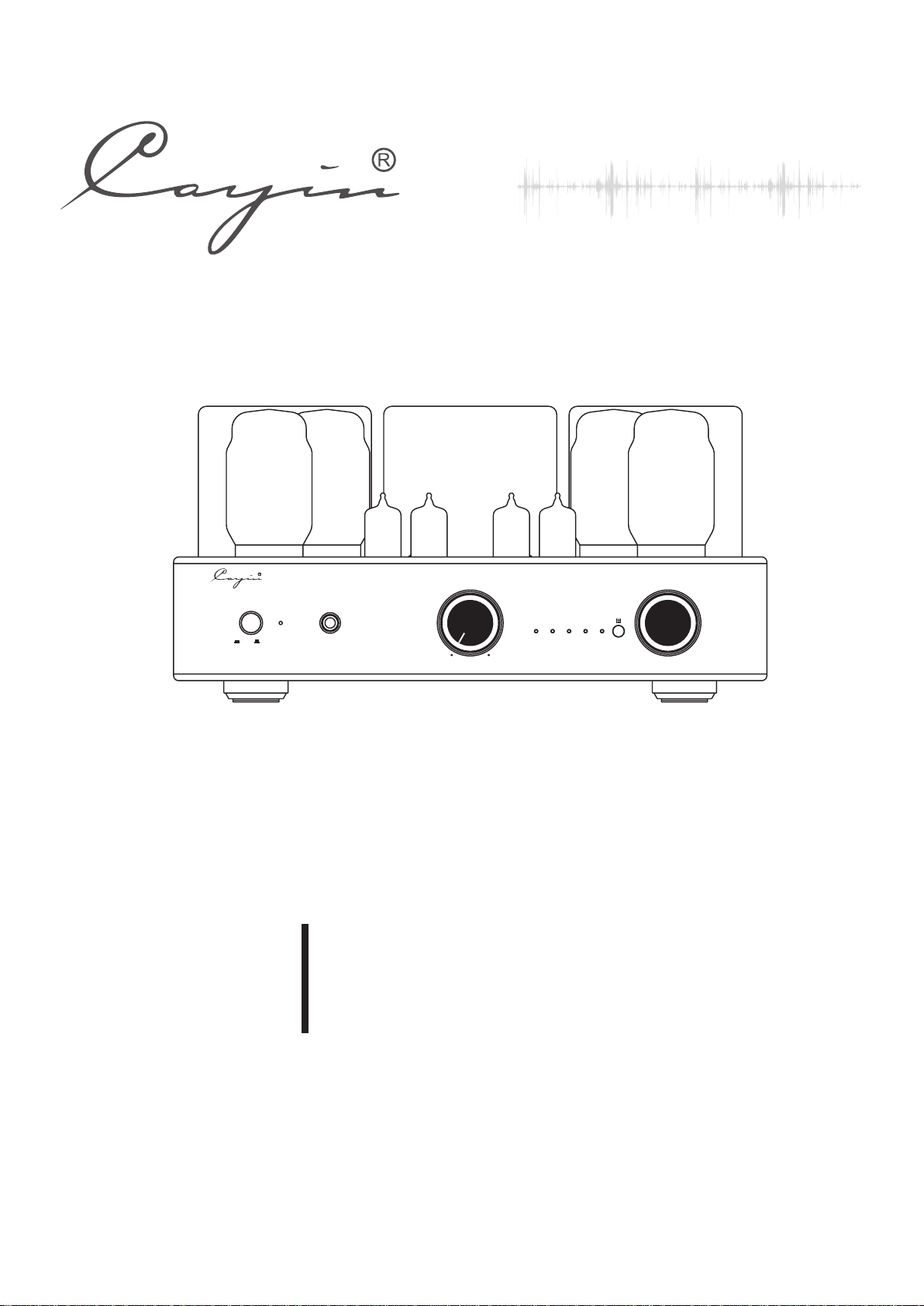
VAC UUM T UBE I NTE GRAT ED AM PLI FIE R CS- 55A
SEL ECT OR
CS-55A
Vacuum Tube Integrated Amplifier
User's Manual
REV:1.1
Page 2

Thanks for choosing CAYIN CS-55A Integrated Amplifier and please read the user's manual
carefully before installation and operation.
In order to prevent damage during transportation, the amplifier is packed with protective foams surrounding
the tubes. Before installation and operation, please remove these foams to avoid any risks.
Vacuum Tube
Table of Contents
Table of Contents
Package Contents…………………………………………………………………………………………………………2
Product Features…………………………………………………………………………………………………………3
Safety Precautions………………………………………………………………………………………………………3
Specifications………………………………………………………………………………………………………………4
Maintenance………………………………………………………………………………………………………………5
Warranty Service…………………………………………………………………………………………………………5
Precautions…………………………………………………………………………………………………………………6
Front Panel…………………………………………………………………………………………………………………7
Rear Panel…………………………………………………………………………………………………………………8
Top Panel……………………………………………………………………………………………………………………9
Remote Control…………………………………………………………………………………………………………10
Operation System Requirement
……………………………………………………………………………………………… 1…………
……………… ……… ………… ……… ………… ……… ………………… ……11
Installation of the driver software
Installation………………………………………………………………………………………………………………13
Tube Replacement ……………………………………………………………………………………………………13
Audio Connection………………………………………………………………………………………………………14
Speaker Connection……………………………………………………………………………………………………15
Turn on……………………………………………………………………………………………………………………16
Small Tips…………………………………………………………………………………………………………………16
Troubleshooting … ……………………………………………………………………………………………………17
How to Install Vacuum Tubes…………………………………………………………………………………………18
1
…………………………………………………………………………………11~12
Page 3
NOTE:
CAYIN CS-55A Vacuum Tube Amplifier is designed and manufactured with our original parts and
reaching the best results. We are not responsible for problems and damages caused by non-original parts
replacement in the amplifier.
Integrated
Package Contents
Please carefully check the package first and then open it.
Package contents include:
1. CAYIN CS-55A 1 piece
2. Remote Control 1 piece
3. (AAA) Battery of 1.5V 2 pieces
4. Users' Manual 1 piece
5. Power cord 1 piece
6. USB cord 1 piece
7. 1 piece
Driver CD
8. Main Fuse 2 pieces
Recommendation:
Keep all packing materials for future use .
NOTE:
Please make sure local voltage level is matched with the input level of the amplifier, which indicates on the rear
panel. T oo low or too high voltage may cause p ro blem. Please contac t our company or ou r local agent if you' ve f ound
improp er v oltage.
All other parts except above are not included.
2
Page 4

Product Features
◆ Hand-made construction with the finest point-to-point wiring.
◆ Two EI output transformers with wide bandwidth are applied.
◆ Specially designed toroid transformer for power supply.
◆ Audio grade capacitors and resistors are used for a better and more sweet sound output.
◆ 12AX7/ECC83 and 12AU7/ECC82 tubes are used in the preamp stage.
◆ Four KT88/EL34 tubes are used for AB1 push-pull amplification.
◆ Triode and Ultralinear selection.
◆ External user Bias Adjustment is accessible with the BIAS meter for monitoring on the top of the amplier.
◆ External Tube Selection Switch between EL34 and KT88 on the rear panel for easy tube replacement.
◆ Four pairs of input include one USB input, one Phono input and two line inputs.
◆ CS-55A takes outstanding USB audio technology which utilizes high speed USB 2.0 receiving and decoding
32bit/384kHz high resolution digital signals.Internal USB DAC which supports asynchronous clocking.
◆ Equipped with remote control.
◆ Soft start function (about 30 seconds).
◆ CS-55A can memorize last operation of the unit once turned off.
◆ High-quality Japanese ALPS motor potentiometer.
◆ Equipped with easily-installed tube cover for protection.
Safety Precautions
1. Unplug the power cord if you are not going to use the product for an extended period of time.
2. The machine will become hot after working for a long time. P lease keep the unit's ventilat ion open and
install the amplifier at a well-ventilated place to avoid troubles and fire hazard.
3. Forbidden to operate when the output is open or shorted.
4. Do not attempt to serv ice this product yourself. Openin g the cover may expos e you to dange rous
voltage or other hazards.
5. We ar e not respo nsible for any problems caused by checking and op ening without permissio n of our
company. For service, Please contact a qualified service technician.
6. Do not place any objects filled with liquids such as vases or some others on the top or around.
7. Clean only with dry cloth.
8. Please move the amplifier carefully not to drop the unit or be subject to other strong shocks.
3
Page 5
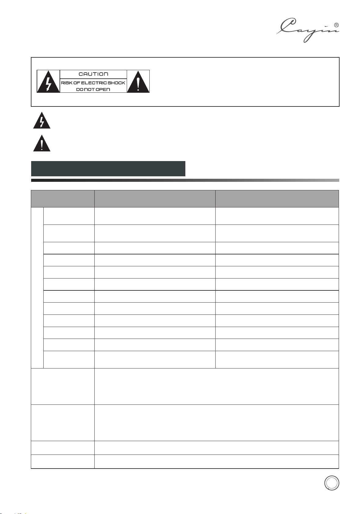
◆ To reduce the risk of electric shock, do not remove the cover.
◆ No user serviceable parts inside. Refer servicing to qualified service
personnel.
◆ To reduce the risk of fire or electronic shock, do not expose the unit to
rain or moisture.
The lightning flash with arrowhead symbol is intended to alert user to the presence of uninsulated
“dangerous voltage” within the product's enclosure that may be of a risk shock to persons.
The exclamation point is intended to alert user to the presence of important operation and maintenance
(servicing) instructions accompanying the appliance.
Specifications
Description
Power Output
Frequency
Response
THD
S/N Ratio
AMPLIFIER
Input Sensitivity
Input Impedance
Output Impedance
Input Terminals
WDH(W×D×H)
Tube
Net Weight
Max Power
Consumption
USB DAC
PHONO
EL34 TUBE KT88 TUBE
TR:20W+20W (RMS )
UL:38W+38W (RMS )
5Hz~48kHz (-3dB) 5Hz~44kHz (-3dB)
1%(1kHz) 1%(1kHz)
92dB 92dB
280mV
100kΩ 100kΩ
4Ω, 8Ω 4Ω, 8Ω
USB,PHONO,CD,AUX USB,PHONO,CD,AUX
360mm×334mm×180mm
12AX7/ECC83×2、12AU7/ECC82×2、EL34×4 12AX7/ECC83×2、12AU7/ECC82×2、KT88×4
17kg 17kg
270W 270W
Compatible with Audio Class 1.0 and Audio Class 2.0
Word length:16 - 32bits
Sampling rate:44.1kHz, 48kHz, 88.2kHz,96kHz,176.4kHz,192kHz,352.8kHz,384kHz
Operating System:Windows XP , Windows Vista ,Windows 7 , Windows 8 , Mac OS(10.6.3
and above)
Input Sensitivity:3mV
Input impedance:47kΩ
RIAA Errors:Lower than ±0.25dB
Total Gain:40dB
S/N ratio:68dB
TRIODE
ULTRALINEAR
3
® ® ® ®
TR:22W+22W (RMS )
UL:40W+40W (RMS )
270mV
360mm×334mm×180mm
TRIODE
ULTRALINEAR
3
Working Condition
Storage Condition
Temperature: 0℃~40℃ Moisture: 20%~80%
Temperature: -20℃~70℃ Moisture: 20%~90%
4
Page 6
Maintenance
NOTE:
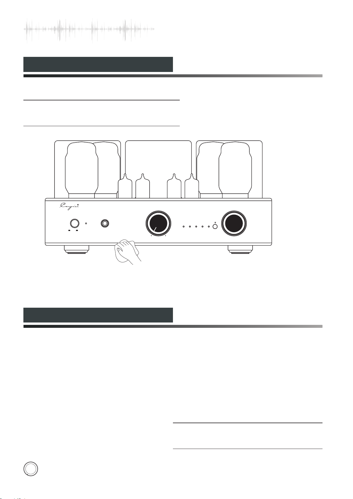
Use the soft dry cloth to clean up the chassis regularly.
◆
◆ Do not use any chemicals for cleaning.
SEL ECT OR
POW ER
ON OFF
PHO NES
Warranty Service
VO LUM E
TR/ U L
AUX
MI N
MA X
USB
PHO NOCD
VAC UUM T UBE I NTE GRAT ED AM PLI FIE R CS- 55A
1.This product is warranted for a period of twelve months beginning from the date of purchase.
2.The defective product must be returned to your dealer or our company for repairing when your dealer or our
company accepts your requirement.
3.The warranty doesn't extend to any product that has been opened by you without permission of our company.
NOTE:
The information in this manual is subject to change without
further notice.
5
Page 7
Precautions
VAC UUM T UBE IN TEG RATE D AMP LIFI ER
MOD EL : CS - 55A
SER .NO .:
Connected to power socket
USB
INP UT
CD
PHO NO
GND
TUB E SEL.
AUX
EL3 4
KT8 8
RIG HT OUTPUT LEF T OUTPUT
ZHU HAI S PARK E LEC TRO NIC E QUIP MEN T CO. ,LTD.
YALIDA
YN-401
Connected to AC INPUT
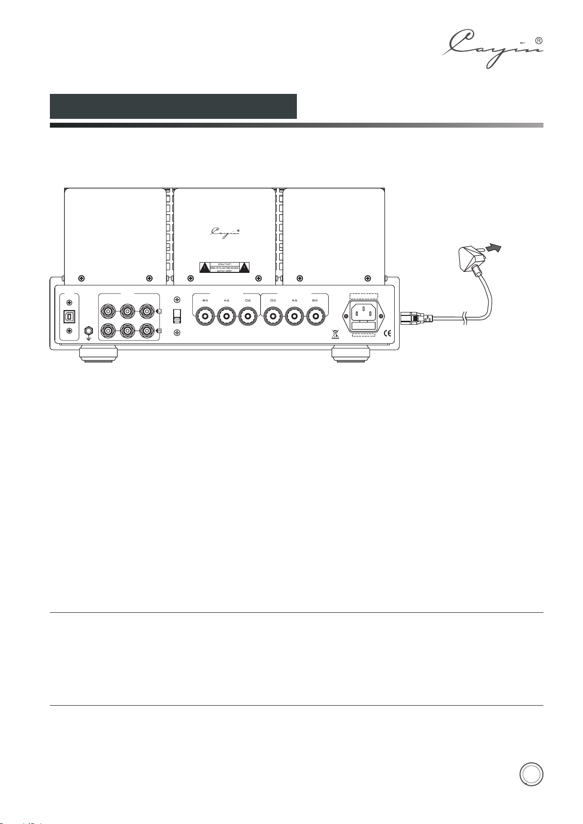
Connection of power cord:
Connect the speaker cables and signal cables first and then insert the power cord into the power socket.
NOTE:
◆ Connect the power only after finishing other connections.
◆ It is normal that power transformer becomes hot for extended period of operation.
◆ Unplug the power cord if you're not going to use the product for an extended period of time.
◆Please make sure corresponding voltage is the same as required. We are not responsible for damage caused by misuse
of unsuitable voltage.
6
Page 8
Front Panel
POW ER
.
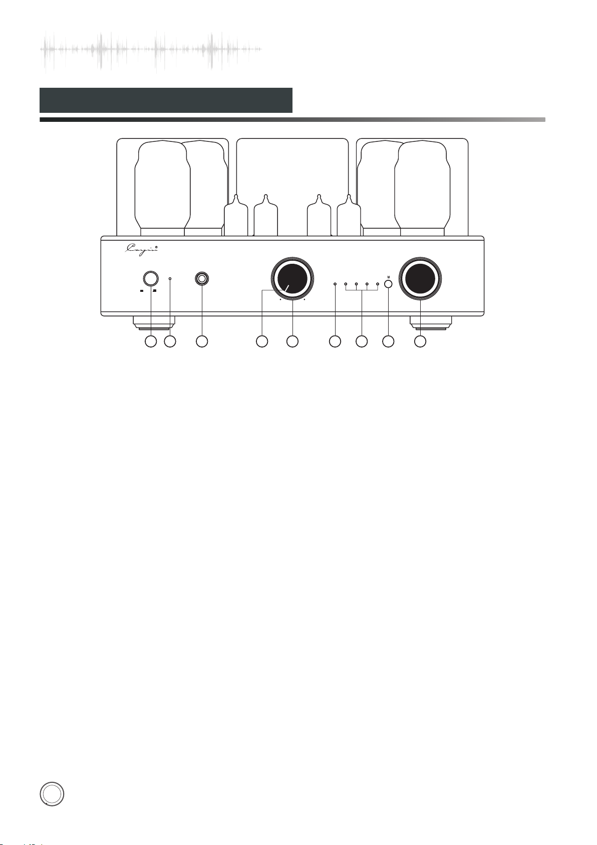
① Power Switch
ON OFF
1
PHO NES
2
3
Used to switch on/off the amplifier.
Note: Unplug the power cord if you're not going
to use the product for an extended period of
time.
②. Power indicator
Turn on the amplifier the power indicator will be
on.
③. Headphone Jack(PHONES)
Enjoy the music with your headphone if you
prefer.
④.
Power Indicator/Mute Indicator
Used to indicate the working state. The indicator
will be on when it is working normally. The
indicator will flicker for 30 seconds when it
delays to work. The indicator will keep flickering
when it is at mute state.
⑤.
Volume Knob
Used to control volume
⑥.TR/UL Indicator:
If the TR/UL LED is Yellow it is working at
TRIODE mode.
VO LUM E
TR/ U L
AUX
MI N
4
Diagram 1:CS-55 A FRONT
MA X
5
6
Or it is Utralinear working model with a Red LED.
Once turned on it will keep working at the same
mode before switching off.
⑦.
Input Selector Indicator
You can hear sound from AUX when AUX
indicator is on.
You can hear sound from CD when CD indicator
is on.
You can hear sound from PHONO when PHONO
indicator is on.
USB Input Indicator: Once USB input has been
selected the indicator will light.
Cayin CS-55A can memorize last operation of
the unit once turned off.
⑧.IR Remote Sensor
Used to receive the code of remote control.
⑨.
Input Selector Knob
Used to select four kinds of audio
sources.The input selection indicator will be
on according to the input audio sources.This
function can be operated on the remote
control.
SEL ECT OR
USB
PHO NOCD
VAC UUM T UBE I NTE GRAT ED AM PLI FIE R CS- 55A
8
7
9
7
Page 9
Rear Panel
VAC UUM T UBE I NTEG RATE D AMP LIF IER
MOD EL : CS - 5 5A
SER .NO .:
USB
INPUT
CD
PHO NO
GND
1
3
TUBE SEL.
AUX
EL3 4
KT8 8
4 5 6 7
Diagram 2:CS-55 A BACK
RIGHT OUTP UT LEFT OUTPUT
ZHU HAI S PAR K ELE CTRO NIC E QUI PME NT CO .,LTD.
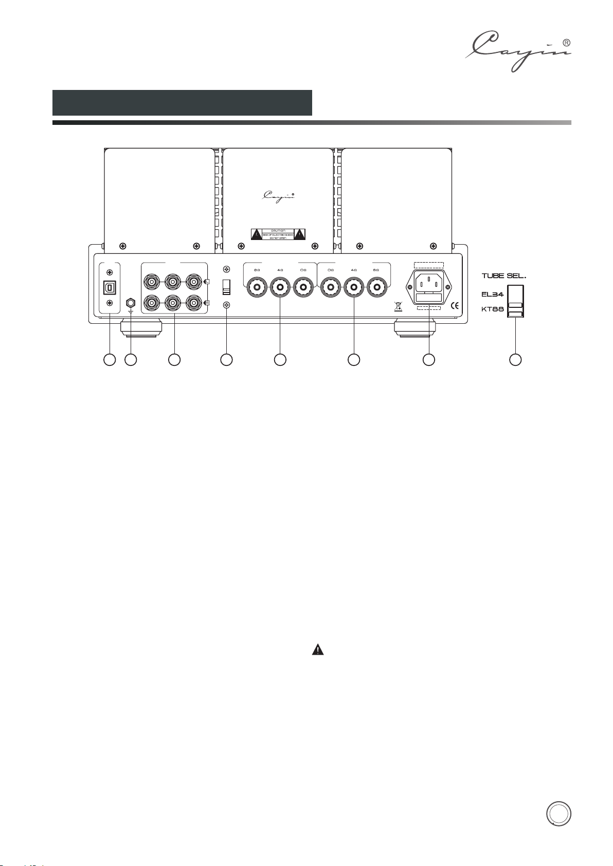
①.USB Interface
Connect to the computer with USB cable.
②.Ground
Ground for Phono input
③.Signal Input Terminal
Used for audio source input.
④.Tube Selector
Select tube EL34 or KT88 .
⑤. Right Channel Output
Used to connect with the right channel of speaker.
⑥. Left Channel Output
Used to connect with the left channel of speaker.
⑦. Power Socket with Main Fuse
Main fuse is located just below the power socket.
Replace the fuse with the same type and value.
42
Method of Power Tube Replacement:
1. Refer to the "Tube Replacement" on page 13 and
find out which kind of tubes can be used for
replacement for CS-55A amplifier.
2.Tube Sel. switch on the rear panel must be turned to
position KT88 if you are going to use KT88 series of
tubes for replacement.
3.Tube Sel. on the rear panel must be turned to
position EL34,if you are going to use EL34 series of
tubes for replacement. Bias adjustment instruction
please refer to the manual instruction on page 9.
Please turn off the amplifier when you are
turning the Tube Sel. Switch.
8
Page 10
Top Panel
1 2 3
4 5
Diagram 3:CS-55 A TOP
6
Diagram 4
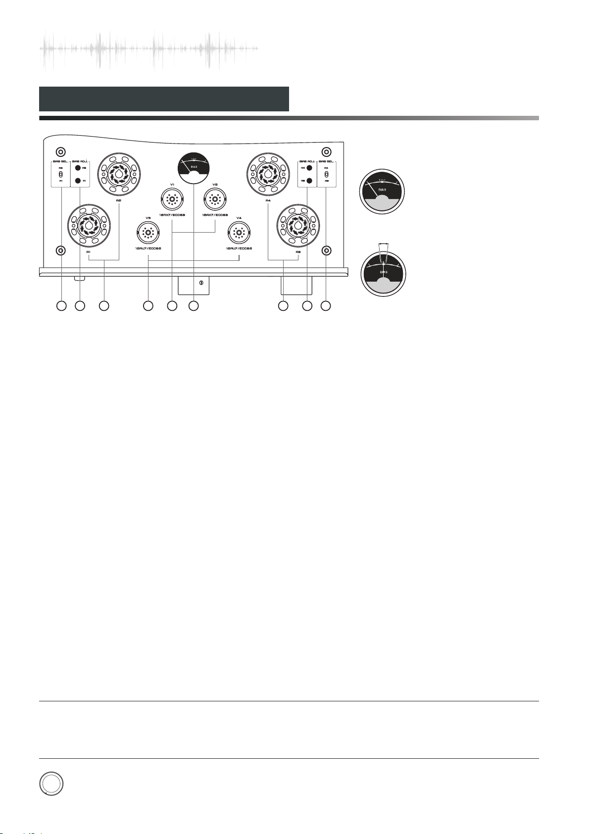
Bias meter when not working
A
Diagram 5
Bias meter during working
Note: When working normally,
the pointer should stay within
3
12
the A zone, still , it would move
for the voltage fluctuation.
Bias Selector Switch(A1、A2、A3、A4)
①.
Used to select corresponding tube for bias
adjustment.
Bias Adjustment Switch(A1、A2、A3、A4)
②.
Used to adjust bias of corresponding power
tube(A1、A2、A3、A4)
A1、A 2、A3、A4:KT8 8/EL34 Tu be
③.
Turn the Tube SEL. to position KT88 on the rear
panel, if you are going to use KT88 Tube.Turn the
Tube SEL. to position EL34 on the rear panel, if
you are going to use EL34 tube.
④. V3、V4:12AU7/ECC82 Tube
⑤. V1、V2:12AX7/ECC83
Bias Meter
⑥.
Tu be
Used to monitor the working current of the
power tube.
Bias adjustment for the power tube:
Turn the BIAS SELECTOR Switch to the
power tube you are preparing to adjust. Adjust
the corresponding BIAS ADJ. small knobs with
flat screwdriver, and inspect the BIAS meter on
the top panel and make sure the pointer keeps
in the center. Bias adjustment for A1, A2, A3,
and A4 are the same. After all have been
adjusted, do it one more time, to make sure all
the bias level of A1, A2, A3, and A4 are the
same.
Sample of Bias adjustment for power tube
A1:
1. Turn the BIAS SELECTOR Switch to A1;
2. Turn the BIAS ADJ. knob A1, until the
pointer of the bias meter keeps in the center.
The same for A2, A3, A4.
NOTE:
1.Be careful of the high temperature of the tubes during operation.
2.Replace the tubes carefully and correctly.
3.Power tubes must be matched for well function.
9
Page 11
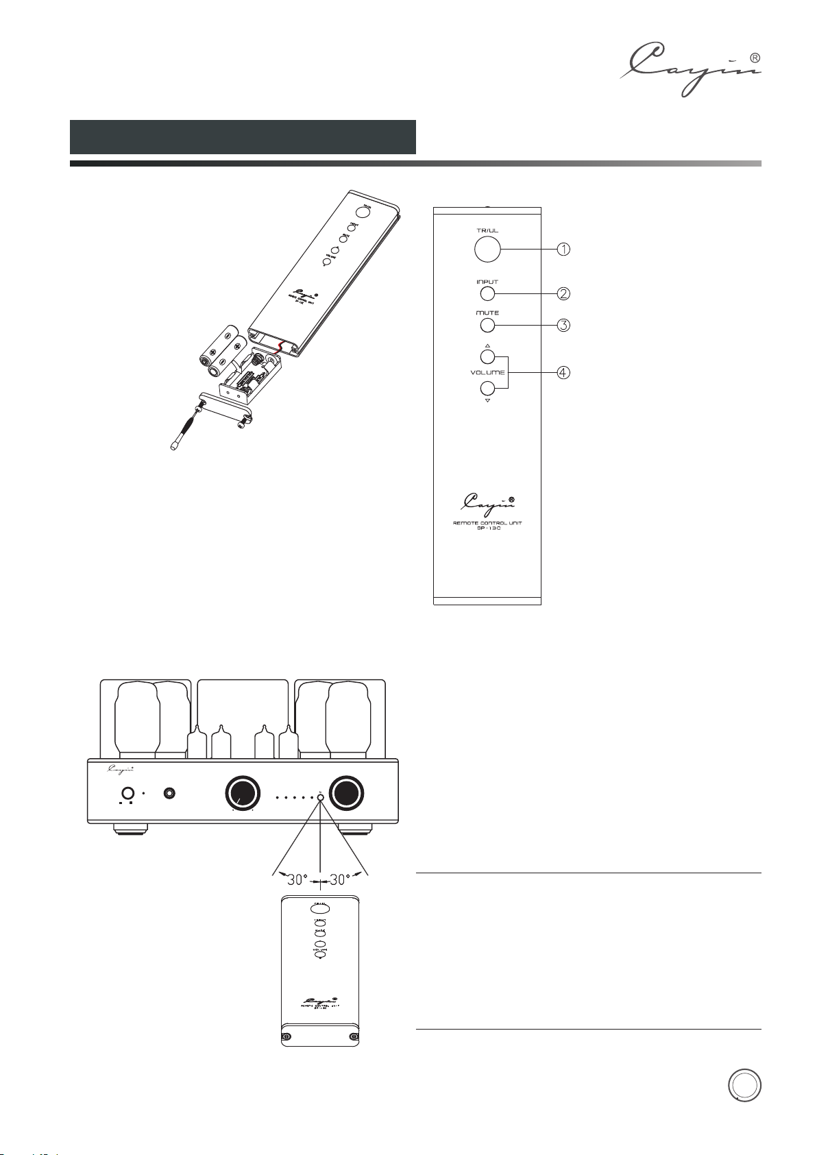
Remote Control
Installation
1.Place the remote control upside up. Screw the rear
cover open with the screwdriver.
2. Pull out the battery case carefully (do not break the
wires connected).
3. Put in the batteries with correct polarity.
4. Push in the battery case and screw the rear cover
close.
POWE R
ON OFF
VOL UM E
TR/ UL
PHONE S
MIN
AUX
MAX
SELE CTOR
USB
PHONOCD
VACUU M TUBE IN TEGRAT ED AMPL IFIER C S-55 A
1. TR/UL
Selector
2. Audio Source Input Selector
3. Mute Button
4. Volume Control Selector
Effective Dis ta nce:about 6m
NOTE:
◆Don't drop the remote control. Keep the remote control dry.
Replace the batteries timely.
◆
Don't mix new and old batteries together and use the
◆
batteries with the same specification.
Take out the batteries if you don't use the remote control for
◆
an extended period of time.
Batteries with high quality are recommended.
◆
10
Page 12
Operation system requirement
Computer should meet the following requirements if you are going to use USB audio:
1.Hardware r equirement:
◆ Intel or AMD CPU with 1.2GHz or higher processing speed.
◆ Higher than 512MB system RAM.
◆ High speed USB 2.0 socket.
2.Operatio n system require ment:
◆ Windows system: Microsoft Windows XP、Windows Vista , Windows 7® and Windows 8®
◆ Mac OS X system: Apply OS X (10.6.3 or above)
◆ Other system: No support for Linux system or others.
3.Suggeste d Media player:
◆ Windows system: Foobar 2000 media player (1.0 or above)
◆ Mac OS X: Audirvana media player
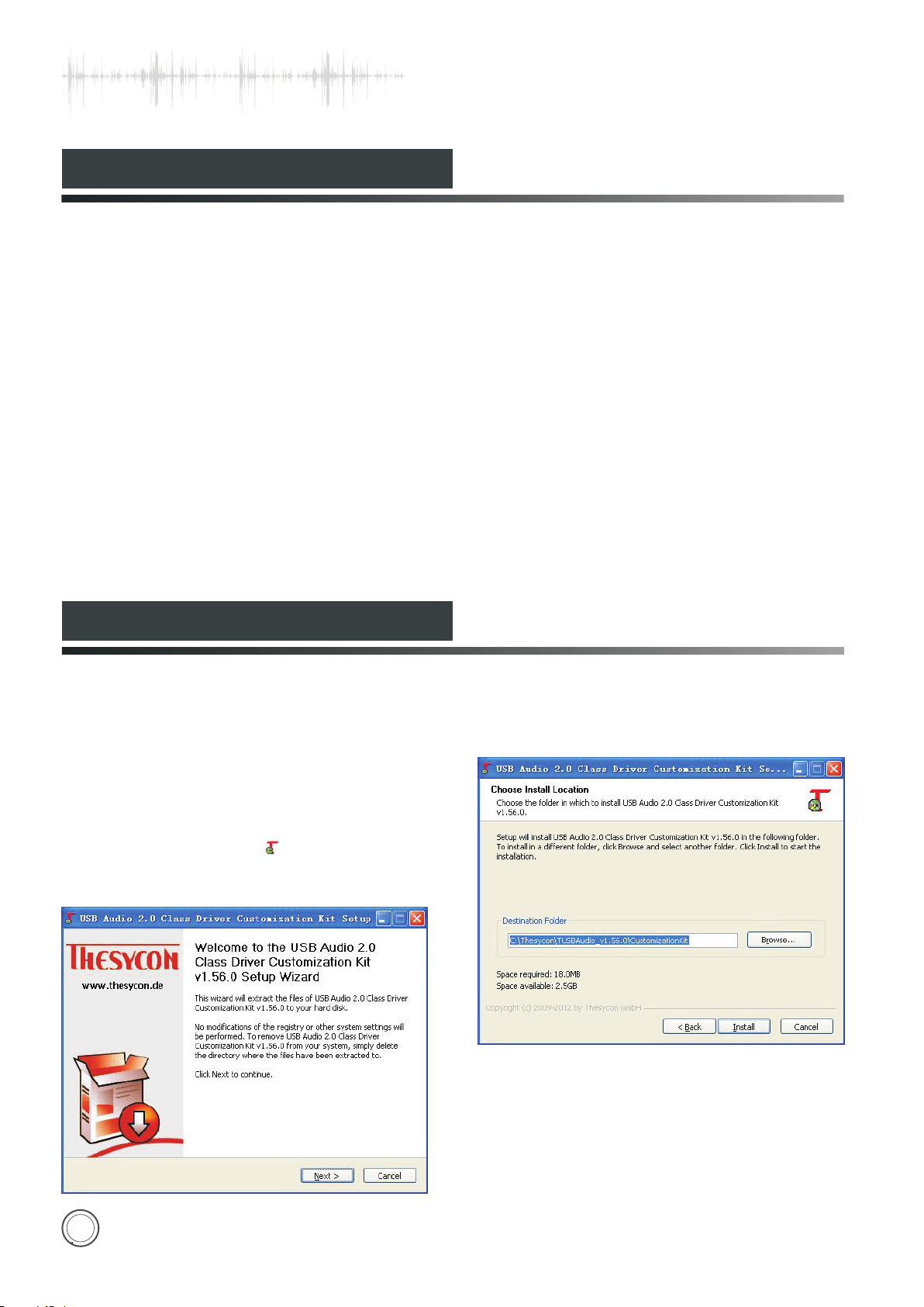
Installation of Driver Software
Install the USB Audio driver software first
before using the PC-DAC input. Please check as
following for the procedures.
1.Connect the amplifier and computer with USB
cable.
2.Put the driver CD into your computer and open
the files. Double-click “ ”to run the diver
installer. As below:
3. Click“Next”to choose the installation
location.
11
Page 13
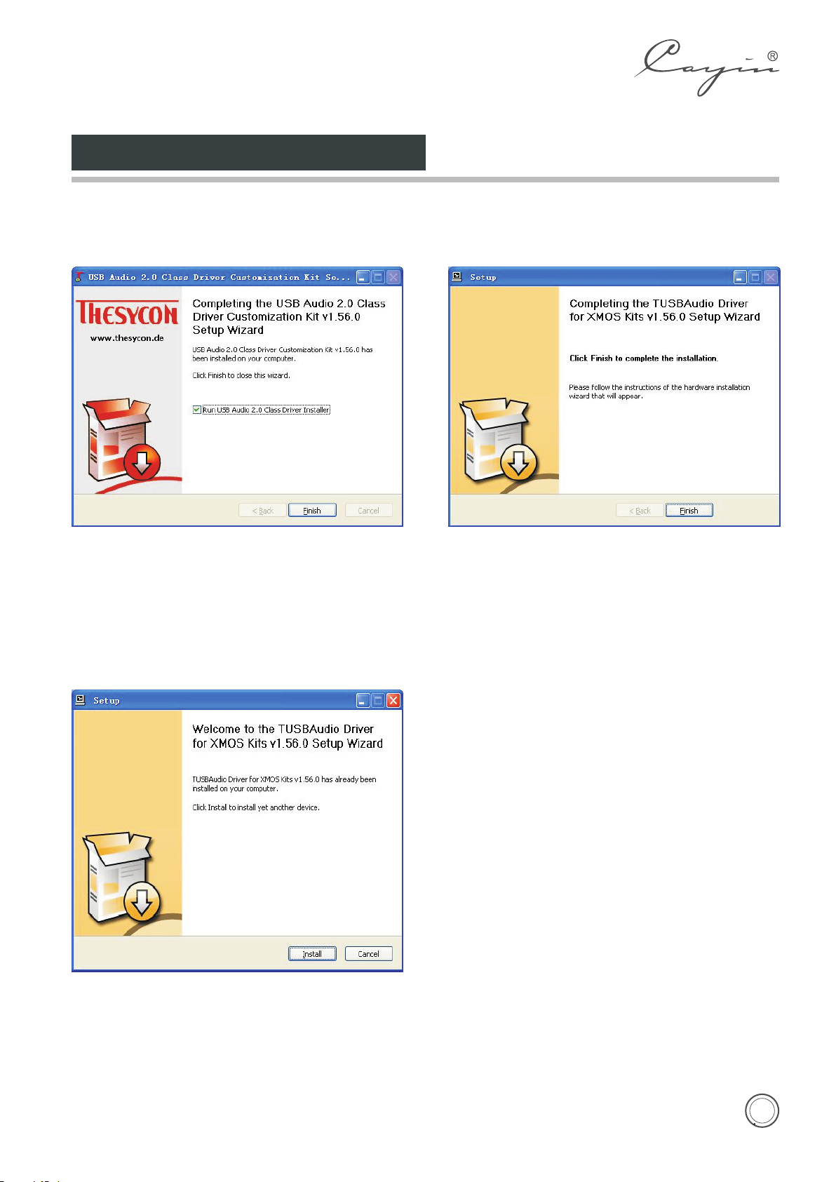
Installation of Driver Software
4. Select the installation location and click Install to
begin installation of the driver software.
5. Click Finish to finish installation of the driver
6. Click Install to begin installation of USB Audio
Class 2.0 driver software.
7. Click Finish to finish installation of USB Audio
software and install USB Audio Class 2.0 driver
software.
Class 2.0 driver software.
8. In Media player please choose Cayin USB DAC
as the output instrument and then you can
music by USB DAC of the CS-55A amplifier.
Note: No need to install the driver software for Mac
System.
12
Page 14
Installation
Carefully read and follow the manual for installation:
◆
◆ In order to avoid being overheated please keep the unit's ventilation open.
◆ Do not expose this appliance to rain or moisture.
◆ Keep the amplifier in a certain distance so that it can be easily connected.
◆ Amplifier should install steadily and make sure all four feet are on the same level.
◆ Keep the amplifier over 15cm's distance to the surrounding walls.
Do not place the machine near heat sources such as radiators, heat registers or other products that
produce heat.
NOTE:
Please make sure local voltage level is matched with
the input level of the amplifier, which indicates on the
rear panel. Too low or too high voltage may cause
problems or shorten the amplifier's life.
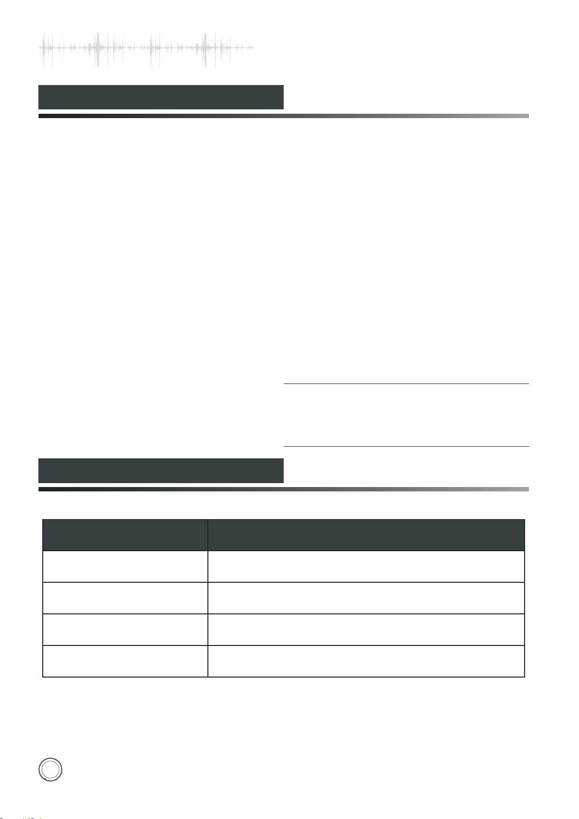
Tube Replacement
Tubes for the Machine Tubes Replacement
12AX7/ECC83
12AU7/ECC82
KT88
EL34
12AX7EH、E83CC、ECC803S
12AU7EH、E82CC、ECC802S
KT88EH、6550、6550EH、KT66、KT90、KT100
6CA7、EL34EH、KT77
13
Page 15
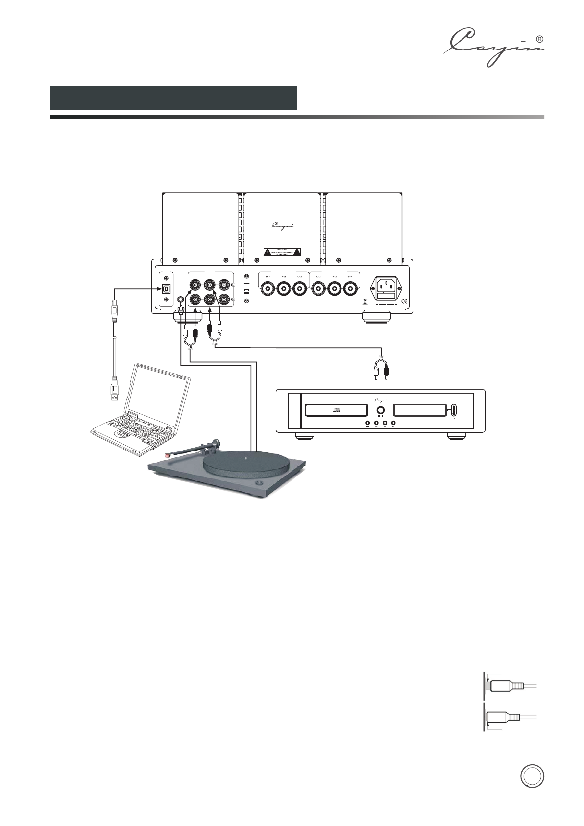
Audio Connection
Please take the following picture for your reference of the connection methods of CS-55A amplifier with other
equipments like Computer, cd player and turntable etc.
Connection with the computer: please use the USB cable attached or other USB cable which complies with
USB 2.0 specification to connect the USB Audio input interface and computer.
VACU UM TUB E INTEG RATED A MPLI FIER
MODE L : CS - 55A
SER. NO.:
USB
INP UT
CD
PHON O
GND
TUB E SEL.
AUX
EL3 4
KT8 8
RIG HT OUT PUT LEF T OUTP UT
ZHUH AI SPA RK ELEC TRON IC EQU IPMEN T CO., LTD.
HIFI COMPACT DISC PLAYER
To au dio out put ter minal
CDT- AM K
15
SOURCE
2
MUTE
kHz
192
bit
ON
OFF
VACUUM T UBE TRAN SISTOR AN ALOG OUTPU T
24
Note:
♦ Do not mix up the positive and negative ends of speaker cables or it will cause short circuit.
♦ Please make sure local power supply is at the same level as the rated voltage level indicated on the rear of
the product before connection.
♦ In order not to cause noise, low-grade function or damage, please do not insert the power cord into the
main socket before all other equipments are well connected.
♦ Once switched on there is a period of 35 seconds for pre-heating of the tubes among which there is no
signal output.
♦ Please switch off the amplifier first if you are going to pull off the USB cable .
NOTE:
•
Please refer to the manuals of other connected equipments during the installation.
•
Do not insert the power cord into the main socket before all other equipments are well
connected.
•
R refers to right channel while L represents left channel.
•
Please take the right guidance for connection as wrong connection may cause noise, low-
grade function or damage.
•
Do not fasten signal cable together with power cable and speaker cables. It will worsen the
acoustic fidelity.
Wrong connection
Right connection
14
Page 16
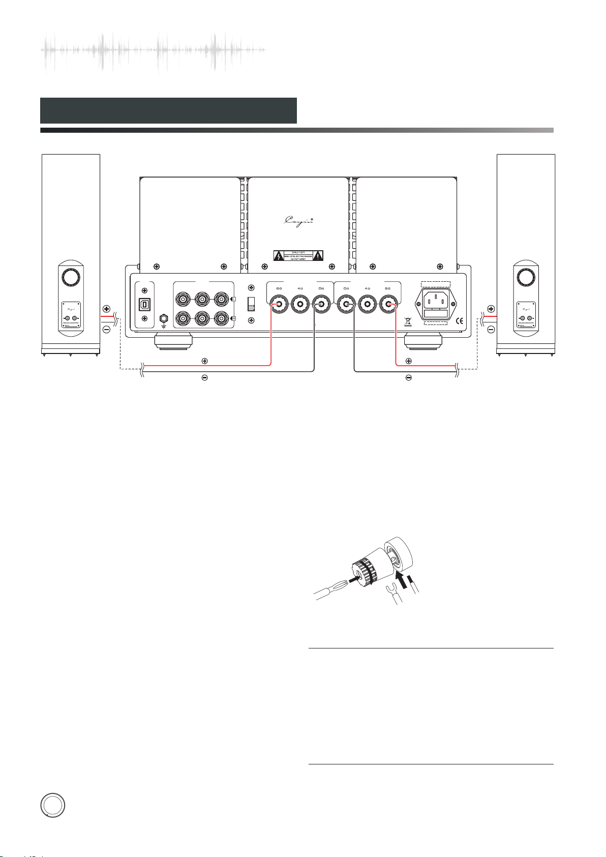
Speaker Connection
VAC UUM TU BE IN TEGR ATED A MPL IFIE R
MOD EL : CS - 55A
SER .NO .:
SPEAK ER(R)
USB
GND
PHO NO
INP UT
CD
RED
BL ACK
TUB E SEL .
AUX
EL3 4
KT8 8
RIG HT OU TPU T LEF T OUT PUT
ZHU HAI S PARK E LEC TRON IC EQ UIPM ENT C O., LT D.
RED
BL ACK
SPEAK ER(L)
Check the impedance of your speakers:
Attach the positive from your speaker to the 4 or 8 ohm terminal and the negative to the 0 ohm terminals
separately. If your speakers are 6 ohm, 4 ohm or 8 ohm (recommended) terminal is preferential and it would not
cause damage to the amplifier.Connecting the left and right speakers according to the guidance can make sure
of the acoustic fidelity.
Connection of speaker cables:
1. Unscrew the terminal knob
2. Insert the speaker cable
3. Screw the terminal knob
15
Banana plug
Normal plug
NOTE:
•
Connect the speaker cables with the amplifier after it is
well connected with the speakers.
• Connect both of the speakers to make sure of the
acoustic fidelity.
• Please notice the signal direction indication of the cables.
• Do not mix up the positive and negative ends of speaker
cables or it will cause short circuit.
Page 17
Turning On
Before turning on the amplifier please make sure all connections are right and power supply is stable.
• Turn on the amplifier, the power indicator will be on and the working indicator will keep flickering.
• The working indicator will be on after 30 seconds. It means that the amplifier is working normally. If the
working indicator is off, please turn off the power and contact with our local agent or our company.
• Select the right audio source channel, adjust the volume to a certain position and then you can enjoy the
music you prefer.
NOTE:
1. When the audio system is under working state, don't
unplug the signal cable or speaker cables, or it will
cause damage to the amplifier and other equipments.
2. It should at least takes 2 minutes before you turn on the
power again, or it will cause damage to the vacuum
tubes.
Small Ti p s
Read the Manual —— Please read the user's manual carefully before installation and operation.
Keep the Manual —— Please keep the manual for future reference.
Warning Signs —— Don't tear off or rub off the serial number.
Operation —— Do the operations as you are instructed in the Manual.
Parts —— If you are going to use parts not supplied by our company like power cord, fuses etc please make
sure that parts you used are compatible with the safety requirements. Or it will cause fire or electric
shock.
Placement —— Put the amplifier on a level place. Make sure that it doesn't bring damage to the children,
adults and the amplifier itself.
Power —— Please make sure the local voltage is the same level as indicated on the rear panel.
Overload —— If the power socket is overloaded with other equipment, it will cause fire or electric shock.
Warranty Service —— Do not open the product and change the components inside yourself. Opening the
cover may expose you to dangerous voltage or other hazards. The warranty doesn't
extend to any product that has been opened by you without permission of our
company.
Troubleshooting —— If any problems when you are using the product, please check according to following
tips to look for the exact reason. Please contact with our company if you can't solve
the problem.
16
Page 18
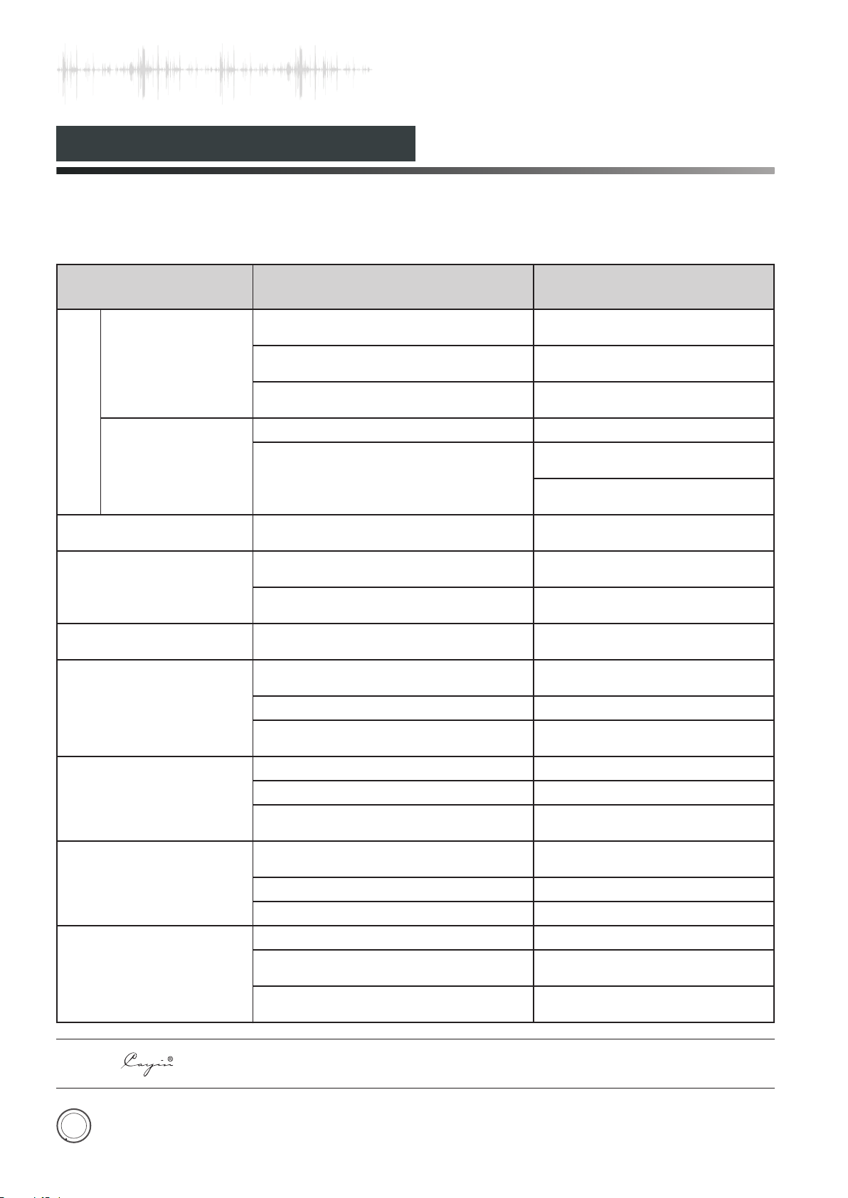
Troubleshooting
Please follow the instruction in the manual in order to keep the amplifier work in its best state. If wrongly
operated and you thought that would be troubles please check according to following tips to look for the exact
reasons.
Problem
Power Indicator is
NO OUTPUT
OFF.
Power Indicator is
ON.
Sound Distortion
Noise output
Sound field Positioning
is not so good.
Malfunction of Remote
Control
Cause
Power cord is not well-connected.
Main fuse is out.
Troubles of inner parts or components.
Volume is at ZERO.
NO signal input.
High input signal level.
Ground of input signal cable is open
or bad contact of the input signal cable.
Components or circuits are in trouble.
Signal input cables or speaker
cables are wrongly connected.
Be disturbed.
Low Battery. Replace with new batteries.
Obstacles between the amplifier and
remote.
USB cable is not well connected. Connect the USB cable well
Check power cable connection or
power outlet connection
Replace with the same type
and value fuse.
Please contact with local
agents or our company.
Turn up the Volume.
Check the function of the
sound source.
Check the input selection and
switch to the proper input.
Turn down the volume to
suitable position.
Replace the input signal
cable with a new one.
Please contact with local
agents or our company.
Reconnect it as suggested in
the manual.
Keep away from the source of
disturbance. Turn off and restore.
Remove the obstacles.
Remedy
Can't lock the USB signal
Computer can't recognize
the device
The sound is abnormal
when the input status is USB
NOTE: is the registered trademark of Zhuhai Spark Electronic Equipment Co., Ltd.
17
USB Audio Device has not been set. Set USB Audio Device
No USB data
The USB line is not according to the
USB2.0 specification
USB driver has not been installed Install the USB driver
USB driver error Restart the computer
USB socket error Choose another USB socket
Computer is too busy
The hardware resource of computer is
too low
Keep the Media Player in working
state
Replace the USB line
Reduce the running application
program
Upgrade the computer if
necessary
Page 19
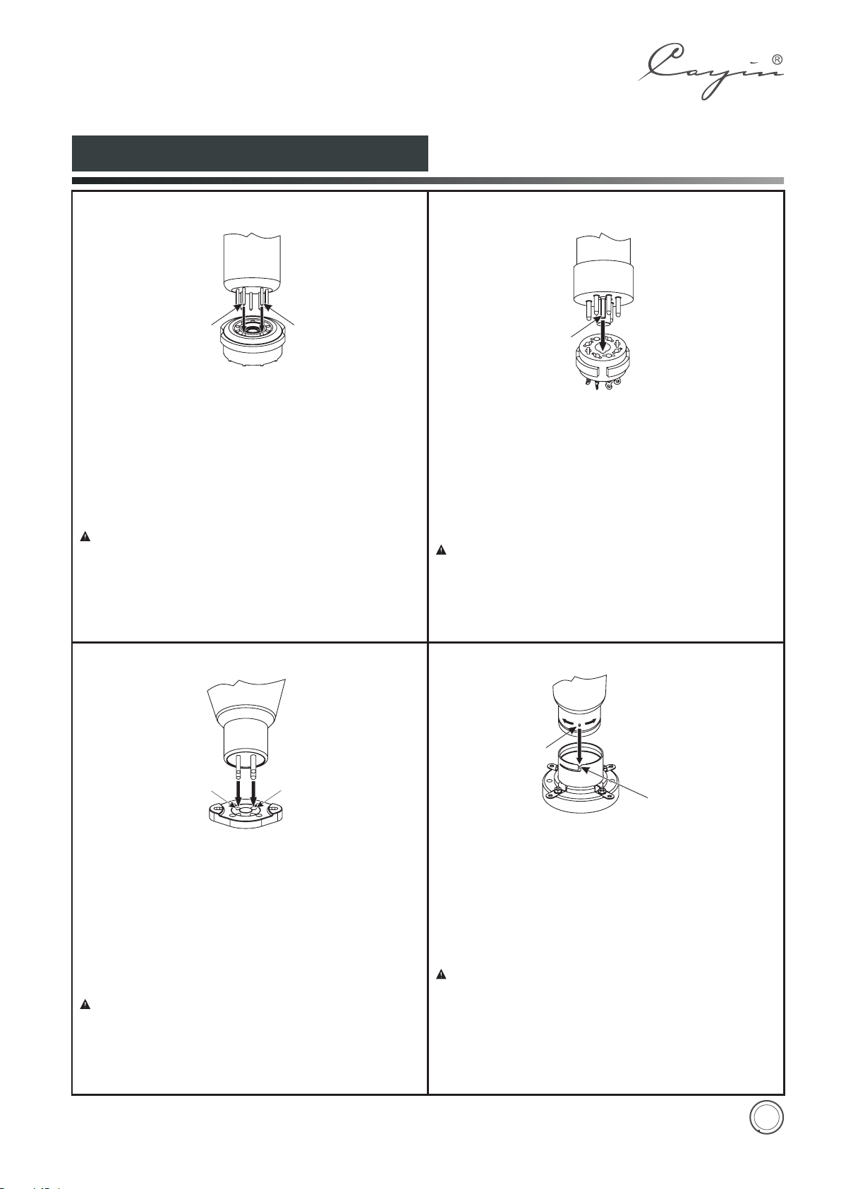
How to Install Vacuum Tubes
How to Ins ta ll 9-Pin Vacuum Tubes
Pin No. 9
Applicable va cu um tube:
12A U 7 ( E C C82)、 12A X 7 ( E C C83)
12AT7(E CC81)、6922(ECC8 8) , etc. 9-Pin vac uu m tubes.
Instruction s to Change and Install th e vacuum tube s:
To insta ll a ni ne-pin v ac uum tu be , alig n the p ins of the va cuum
tube with the holes of th e tube socket and inser t th e tu be
vertically up a nd d ow n (as shown in the fi gu re a bove).
Pin No. 1
、 5BK7、 12B H 7、
Please not e that when i ns ta lling the nine-pin vacuum
tube, pay a tt ention to the a li gnment of the v ac uu m tube
pins with t he holes o f the tube s oc ke t. Otherwise w rong
insertion will ca us e damage to the vacuum tube and
prevent the amp li fi er from working prope rl y, which m ay
lead to failur e of t he a mp li fi er.
How to Ins ta ll 8-Pin Vacuum Tubes
Posit ion ing Pin
Applicable va cu um tube:
KT150、 KT170、 KT8 8、 655 0、 EL3 4、 6V6、 6SN7、 6SL7、 5AR4 ,
etc. 8-pin vacu um t ub es.
Instruction s to Change and Install th e va cuum tube s:
To ins ta ll a n ei gh t- pin va cuum tube, align the p ositioning pin of
the tube with the groove s in the posi ti oning holes of the tu be
socket, and install the tube by pulling up and down vertically
(as shown in the fi gu re a bove).
Please note th at wh en inst al li ng th e eight -p in va cu um tu be ,
pay a tt en tion to the al ig nment o f the v acuum t ub e posit io ni ng
pin with th e positioni ng hole of th e tube so ck et . Otherwi se
wrong insertion wil l cau se da ma ge to th e vac uum tube and
prevent th e ampl if ie r from working properly, which m ay lea d to
failure of the am pl if ier.
How to Ins ta ll 4-Pin Vacuum Tubes
Thi n Pin
Sma ll Hole
Applicable va cu um tube:
300B、2A3 etc. 4-p in v ac uum tubes .
Instruction s to C hange and Install t he v acuum tubes:
To install a four -p in vacuum tube, p le ase pay atten ti on to the
thickness o f diffe rn et pins o f the v ac uu m tube an d the s iz e of
the tub e socket hole. Thick pi n shoul d be al igned w it h the b ig
hole, and t he thin pin should be a li gned with the s mall hole.
Install the tu be ve rt ically up an d dow n (as shown in th e f ig ur e
above).
Please note that w he n in st alling the f our-pin vacuum tube,
pay attention to the thickne ss o f di ffernet pins of the vacu um
tube and the size of the t ube so ck et holes. Otherwise wrong
insertion will c au se damage to the vacuum tube and prevent
the ampli fi er from w orking pr op er ly, wh ic h may l ea d to fa il ur e
of the amplifie r.
Thi ck Pin
Big H ole
How to Ins ta ll Big 4-Pin Vacuum Tubes
Posit ion ing Pin
Posit ion ing Pin S lot
Applicable va cu um tube:
845、805、211 et c. 4 -pin vacuum tubes .
Instruction s to C hange and Install t he v acuum tubes:
To in stall the big four-pin va cu um tu be, align the vacuum tube
positioning pi n wit h p os itioning pin slot of the tube soc ke t a nd
then rotate 4 5° clockwis e to tighten. ( As shown in t he picture
above). To tak e ou t the b ig f ou r- pin va cu um tub e, turn the t ube
45° countercl oc kw ise and take it out u pw ar d after looseni ng .
Please no te that when installing the bi g four-pi n vacuum
tube, pay att en ti on to the align me nt of the vacuum tu be
positioning pi n wit h p os itioning pin slot of the tube soc ke t a nd
then r otate 45° cl ockwise to t ig hten. It i s stri ct ly forbid de n to
install th e v acuum tube wh en the po si ti oning pin i s o ff or
missing. Otherw is e wr ong insertion wil l ca us e da mage to the
vacuum tube and p re vent th e a mp li fier from wo rking p roperly,
which may lead to f ai lu re of the amplifi er.
18
 Loading...