

Page 1
UK
Thermal heat alarm device
Commercial reference: 3103-003
Developed by CAVIUS
This Thermal Heat Alarm is designed for areas not
suitable for smoke alarms due to high risk of false
alarms such as; kitchens, garages or workshops.
PLEASE READ THE USER GUIDE
CAREFULLY BEFORE INSTALLATION AND
RETAIN FOR FUTURE USE.
TECHNICAL INFORMATION
Cavius heat alarm detects:
1) rapidly increased temperature level
2) absolute heat level of 58 degrees C.
The maximum number of alarms that can be interlinked within a house group are 32.
Please note: These must be alarms from the CAVIUS
The distance between interlinked alarms depends
on the house layout and they should always be
tested after installation. It is not advised to get
more than 10m distance between two alarms.
Diameter: 65mm. Height: 44mm.
The alarm is powered by a replaceable 3v
CR123A lithium battery. Please note that correct
operation of the heat alarm device is ensured by
use of one of the following batteries: DURACELL,
PANASONIC or HUIDERUI.
Interlinked by RF: 868 MHz.
Complies to standards: EN54-5 class A1/R,
EN300-220.
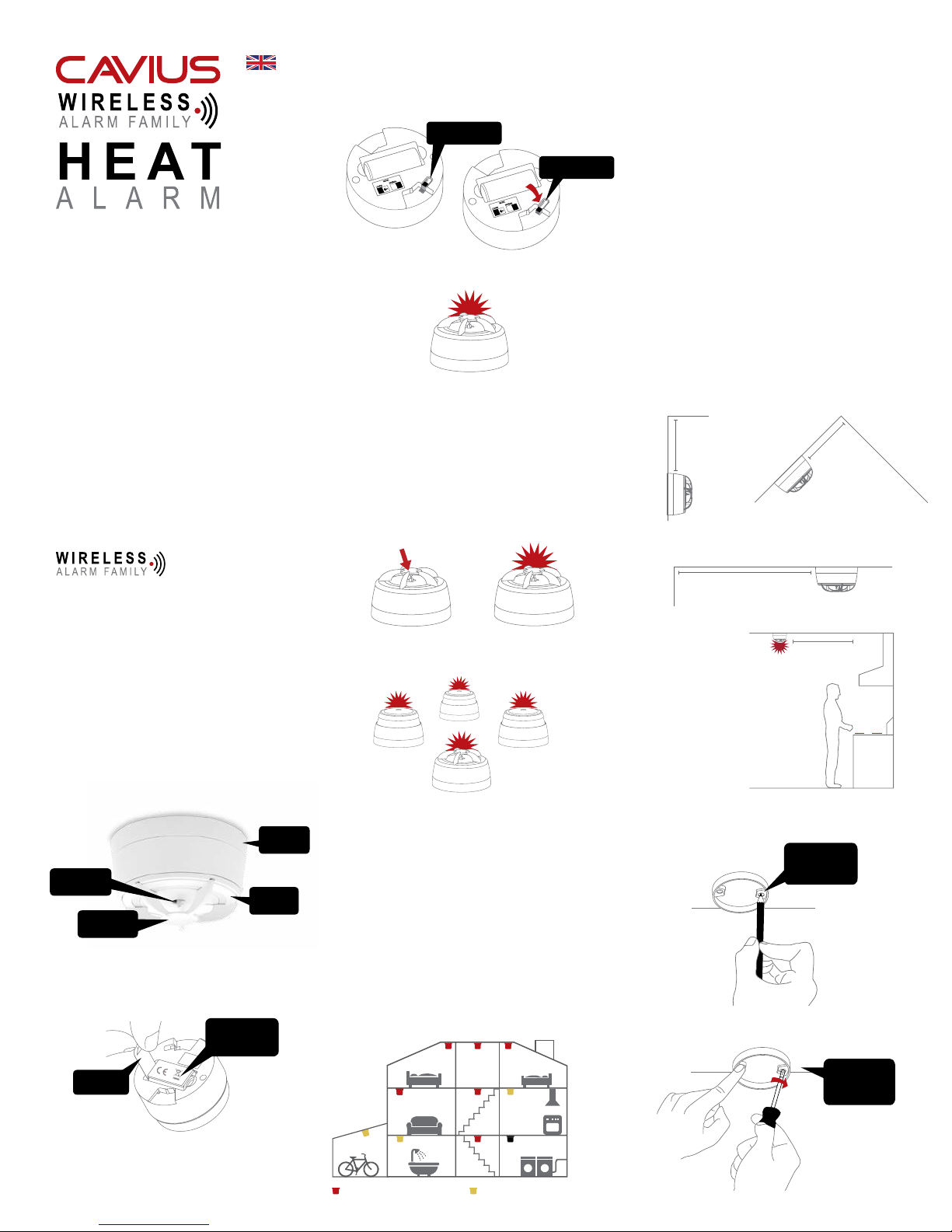
MOUNTING
BASE
THERMISTOR
RED LED
TEST BUTTON
1. HOW TO SET UP AND CONNECT ALARMS:
Start by pulling out the battery isolation strip as
shown.
DO NOT
REMOVE THE
PRODUCT LABEL
ISOLATION
STRIP
All alarms that need to be connected in the
house should be put into ‘Learn Mode’ by sliding
the switch on the back of the alarm to the ‘Learn
Mode’ position.
NORMAL MODE
LEARN MODE
The red LED will light up to indicate that ‘Learn
Mode’ has been selected.
Please note that when the alarms are placed
in ‘Learn Mode’ they can’t be inserted into the
mounting base.
Do not take out the battery during ‘Learn Mode’ as
this will interrupt the learn process.
Press and hold the test button at one alarm only,
until it beeps and the LED ashes. This alarm will
become the master and will start sending out a
specic house code to the other alarms.
As the other alarms receive the specic house
code, they will also ash the LED light.
When all alarms flash the red LED, they are
connected and can be switched out of ‘Learn
Mode’ and installed.
2. THE BEST AREAS TO INSTALL THE HEAT
ALARM:
• Areas not suitable for smoke alarms due to high
risk of false alarms
• Kitchen area
• Bathroom
• Garage or workshop
Additional alarms increase the security.
3. AREAS WHERE NOT TO INSTALL HEAT-
ALARMS:
• In rooms where the temperature goes outside
-10ºC to +50ºC.
• Bedrooms
• Lounge
• Dining room
• Hallway
• Family room
NOTE: In areas where smoldering res occur
over aming res, photoelectric smoke alarms
are still the best to be installed.
4. PLACEMENT:
The heat alarm is design to be installed on a ceiling
or wall. Do not install to close to the oven/hob/
stove (see drawing).
For wall installation:
Ceiling
Wall
Minimum 30cm and
maximum 50cm from
ceiling
Peak ceiling
Minimum 50cm
from peak
For celling installation:
Wall
Ceiling
Minimum 50cm
from wall
Ceiling
Minimum 30cm
and maximum 50cm
from stove
5. INSTALLING THE HEAT ALARM:
Detach the alarm from the mounting base by
twisting counter clockwise.
MARK UP
SCREW HOLES
WITH A PEN
Use the mounting base ring to mark the screw
holes on the ceiling or the wall.
USE THE
ENCLOSED
SCREWS AND
PLUGS
Please note: The product label must not be
removed as it contains important information
regarding the product.
Minimum smoke alarms Minimum heat alarms
Page 2
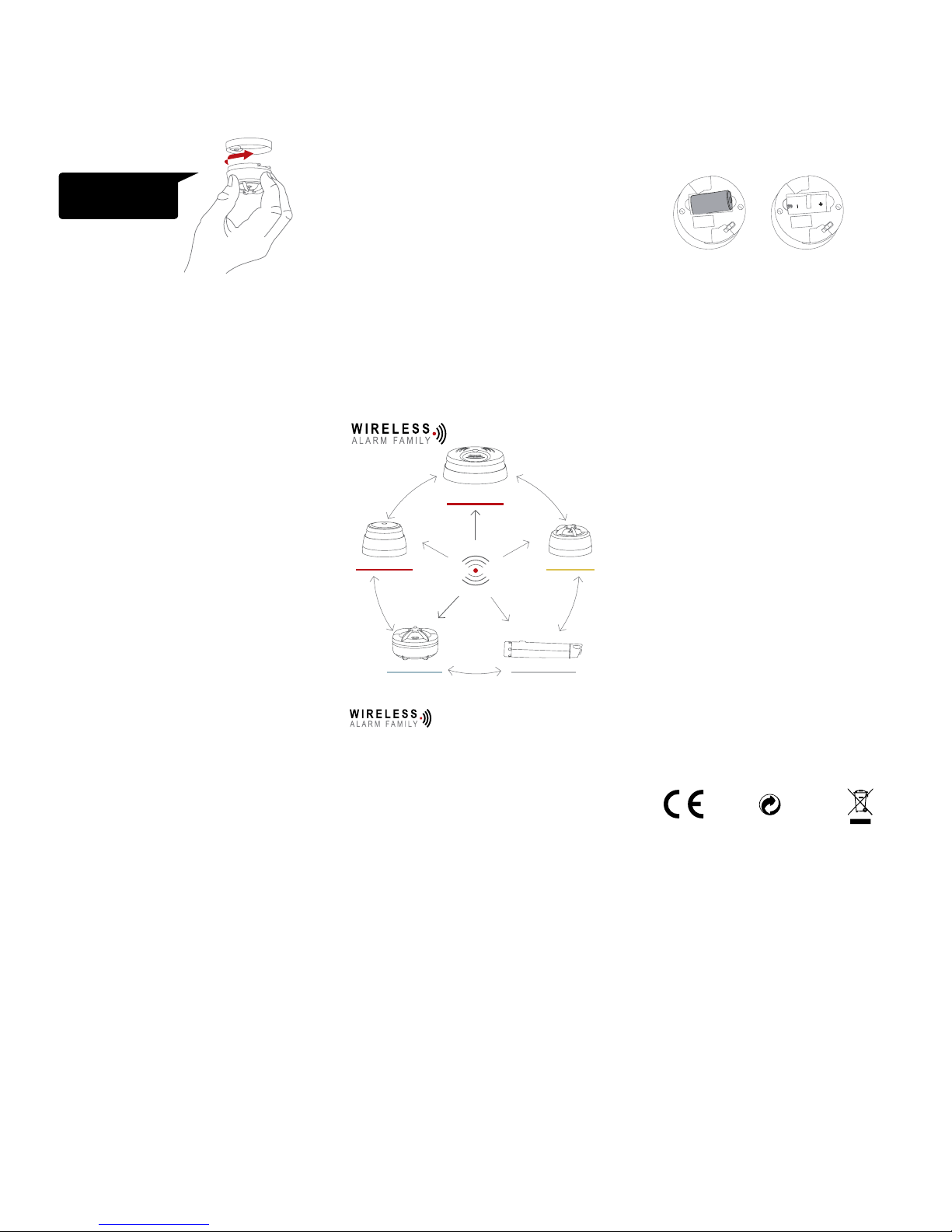
Once the mounting base is installed, attach the
alarm by twisting clockwise until it clicks. If the battery is either missing or inserted incorrectly, or the
switch is in ‘Learn Mode’, the heat alarm will not be
able to click into the mounting base.
CLICK THE HEAT ALARM
FIRMLY INTO THE BASE
TO LOCK
6. TEST FUNCTION:
After installation, and at least once per quarter,
test all of your alarms to ensure they are operating
correctly and are within range of each other.
It is recommended to check visually every week if
the LED ashes correctly (every 48sec.)
Press the test button on any alarm for 2 sweeps of
alarm signal 1 (--- --- ---) - Please refer to section
8. This will send out a test signal from the alarm; all
other connected alarms should receive the signal
within a short time. The alarms will emit a short
beep and the LED will ash every 8 seconds for
2 minutes.
NOTE: Test function also allows to send a depleted
RF signal to ensure an optimal operation in normal
conditions.
When the test signal is sent out, the alarms will
respond in two ways:
Smoke alarm signal: --- --- ---
Heat alarm signal: --- --- ---
Flood alarm signal: - - -
CO alarm low level signal: - - -
CO alarm high level signal: --- --- ---
Please note that only the originating alarm’s LED
will ash, so it can be identied.
9. PAUSE/HUSH FUNCTION:
If the heat alarms are to set into a false alarm
by cooking, replace, etc. they can be paused
for 10 minutes by pressing the test button on
the originating heat alarm only (indicated by the
ashing LED).
The reason of this is that it is necessary to locate
the source of the alarm before using the hush
function. This is to make sure that it is not a life
threatening situation.
10. ADD EXTRA DEVICE:
MAINS POWERED
SMOKE ALARM
SMOKE ALARM
HEAT ALARM
12. BATTERY REPLACEMENT:
To replace the battery, detach the heat alarm from
the mounting base by twisting counterclockwise.
Replace the battery respecting the polarities.
Attach the alarm in the mounting base by twisting
clockwise until it clicks, and test the alarm.
13. TROUBLE SHOOTING:
If you are experiencing false alarms with just general
cooking, you may have your heat alarm too close
to the cooking hobs and stove. Try reinstalling
slightly further away to alleviate any issues.
If the heat alarm does not work when the test button
is pushed, the probable cause is a faulty battery.
Check if the battery is worn out and replace it.
Always test the alarm after replacement of
battery.
If the problem continues, please visit www.cavius.
com for any trouble shooting.
14. OTHER INFORMATION:
Do not paint the alarm.
Disposal: For battery and product, please dispose
properly at the end of life. This is electronic waste
which should be recycled.
1. A single beep every 8 seconds indicates that the
alarms are connected and functioning.
2. Three short beeps every 8 seconds indicates a
heat sensor fault.
If required this indication can be stopped early on
each alarm by a short press of the test button.
If the problem continues, please visit www.cavius.
com for any trouble shooting.
7. NORMAL MODE:
In normal mode the LED will ash every 48 seconds
to show correct operation.
8. ALARM MODE:
When a rapid and constant change of temperature is detected, the heat alarm will go into ‘Alarm
Mode’. It will sound the alarm signal and the LED
will ash.
The heat alarm will also transmit the alarm signal
to the other connected alarms, which will also
sound the alarm signal after a short delay.
The CAVIUS Wireless Family have two different
alarm signals:
Alarm signal 1 (--- --- ---) is life threatening
alarms, like a smoke alarm.
Alarm signal 2 (- - -) is a non life threatening
alarm, like a ooding alarm:
FLOOD ALARM
SMART REMOTE
All CAVIUS interconnected alarms within the
can be added to the system as
they run on the same frequency and use the same
data protocol.This means that the wireless system
can consist of a combination of smoke, heat, ood
etc.
Place all alarms into ‘Learn Mode’ and repeat
section 1.
Always test connection to all devices by repeating
test function section 6 after adding devices.
11. LOW BATTERY SIGNAL:
Your product has a 5Y battery life.
When the battery is starting its end of life, a short
beep will sound out every 48 seconds for 30 days.
The alarm effected by the low battery will only
beep, no other connected alarms will sound.
It is safe to change batteries in the alarms without
going through the learn process again – they will
not forget the codes during the battery change
process.
Note the local country regulations regarding
installation.
The CE mark afxed to this product conrms its
compliance with the European Directives which
apply to the product.
Tested to comply to the standard of system heat
alarms EN54-5 class A1/R.
Alarm condition aural signal pattern according to
ISO 8201.
All Rights reserved: Cavius Aps assumes no
responsi bility for any errors, which may appear
in this manual. Furthermore, Cavius Aps reserves
the right to alter the hardware, software, and/or
specications detailed herein at any time without
notice, and Cavius Aps does not make any
commitment to update the infor mation contained
herein. All the trademarks listed herein are owned
by their respective owners. Copy right © Cavius Aps.
Developed by CAVIUS Aps Julsøvej 16, DK-8600
Manufactured in P.R.C.
126773 rev1
 Loading...