

Cavity Sliders WallMountTrack, SofStop Installation Instructions Manual
Installation
Instructions
Read through the notes carefully before beginning as
different mounting plate positions and setups may be
required for different configurations.
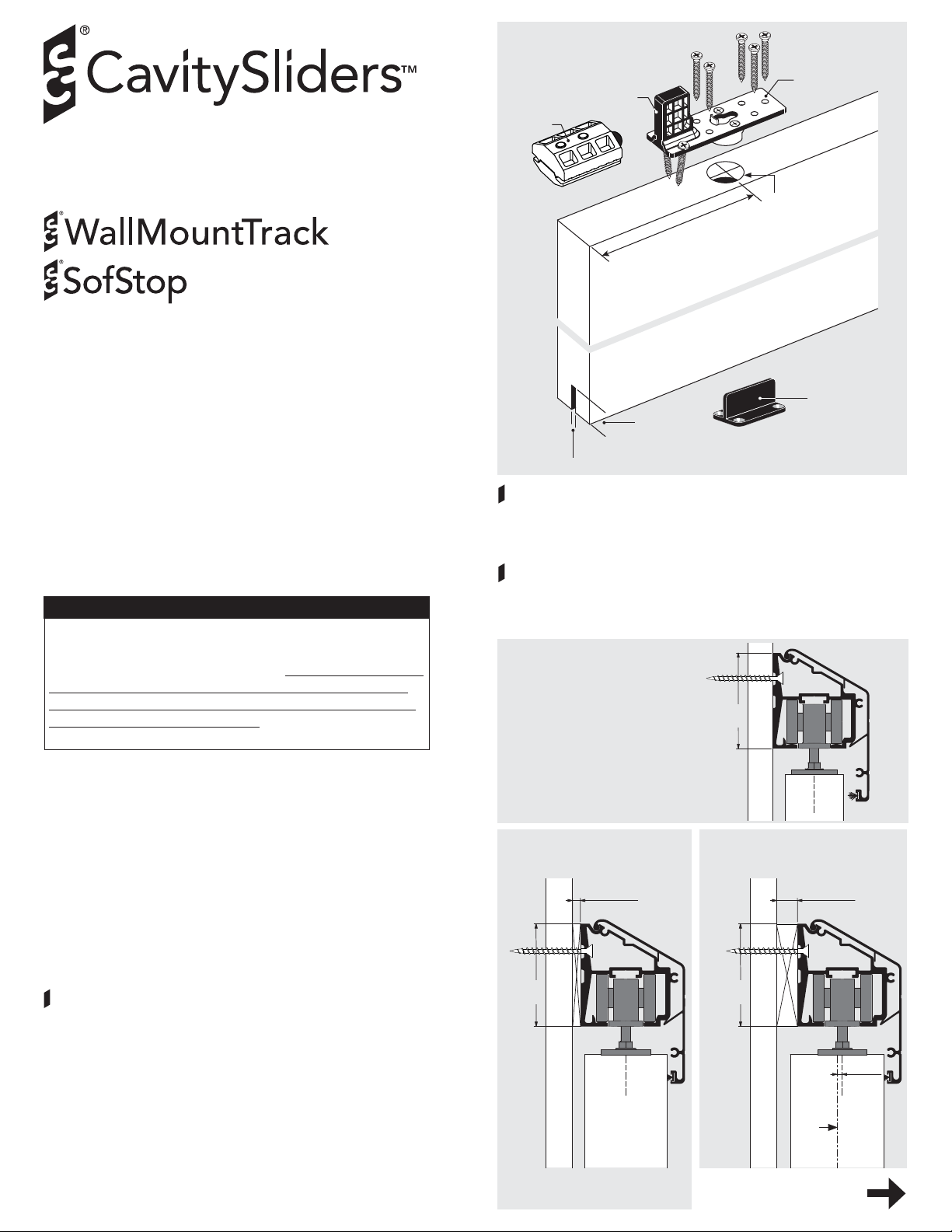
Fit screws
as shown
Track
stop
Black
plastic
stop
150mm (6”) to
center of boss
hole
20-21mm
(13/16”)
5-5.5mm (1/4”)
Mounting
plate
Drill ø25mm (1”)
13mm (1/2”)
deep
T-G uid e
1
Groove the door.
At the bottom of the door, cut a groove to the dimension and
tolerance shown. Make it central to the door thickness and
absolutely straight.
PAGE
IMPORTANT
CS carriages require a clean track running sur face free
of any contamination or damage.
After installation but before lining, clean the full length
of the inside running surface of the track with a soft
rag to ensure no dirt, grit or aluminum swarf get into
the track. TAPE UP THE TRACK to ensure no dust or
debris enter the track during building works.
Please Note: Most of the time the carriages, SofStop
mechanism and activators can be inser ted into one end
of the track after the track is mounted.
If there is no room, you will need to insert these
components before mounting the track.
1. Prepare the doors.
CS WallMount Track is designed to suit doors from
35-45mm thick (1-3/ 8” to 1-3/4”) as standard.
If your doors are 2” thick, you will need to add a spacer.
If your doors are 2-1/4” thick, you will need to add a
spacer and offset the mounting plate as shown.
Drill mounting plate holes.
a) 1-3/8” & 1-3/4” thick doors.
Drill front and rear holes 150mm (6”) in from the edge of
the top of your door leaf as shown (right).
Note: these mounting plates must be placed exactly in
the center of the door thickness.
b) 2” thick doors: Drill holes as above.
c) 2-1/4” thick doors: Drill holes as above, but offset
them 6.35mm (1/4”) from the center of the door leaf as
shown.
Fit mounting plates.
Screw the mounting plates to the front and rear top edge
of the door, making sure the black plastic stop is facing the
edge of the door.
1-3/8” & 1-3/4” thick doors
62mm
(2 -7/ 16 ”)
2” thick doors 2-1/4” thick doors ONLY
Offset mounting plate by 1/4”
6.35mm spacer
(1/4”)
62mm
(2-7/16”)
© Cavity Sliders USA Inc.
Drawings are not to scale.
62mm
(2-7/16”)
C
L
Go to page 2 (overleaf)
12.7mm spacer
(1/2”)
6.35mm
(1/4”)
Center
line of
door
C
L
2
PAGE
2. Fix the track.
CS WallMountTrack is screw fixed from the side through
the pre-machined slots in the extrusion.
Hole centers are pre-set at 406mm (16”) apart.
Screw fix the track to the stud wall using #8 screws,
ensuring it is level and solid enough to support the door
weight.
Pre-machined
slots
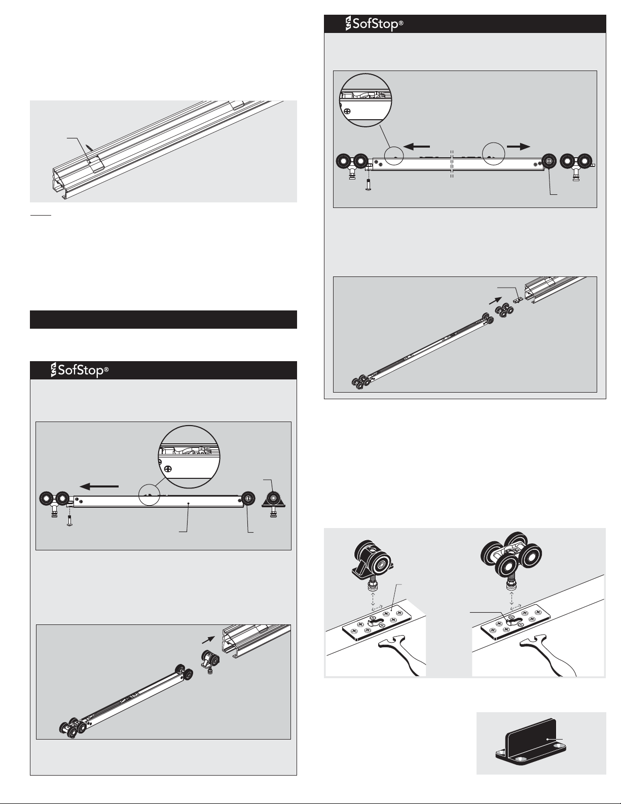
Twin (Soft Open & Soft Close)C
The twin SofStop mechanism fits together as shown below.
Push front and rear pickup mechanisms in the direction
shown to charge them.
Rear pickup
mechanism
(push this way to
charge)
Rear
carriage
Front
carriage
Front pickup
mechanism
(in charged
position)
Note: for 2” thick doors, a 6.35mm (1/4”) spacer is required.
For 2-1/4” thick doors, a 12.7mm (1/2”) spacer is required.
For fixing to concrete walls, the use of masonry anchors is
recommended. You may need to open the existing holes to
suit the type of masonry anchor you have selected.
Clean out all swarf and debris from the track before hanging
the door.
3. Fit the carriages (A, B or C).
A. Standard M6/M8 (non-SofStop)
Insert the carriages into the track, taking care not to damage
the wheels on the sharp edge of the track.
Single (Soft Close)B
a) The single SofStop mechanism fits together as shown
below. Push pickup mechanism in the direction shown to
charge it.
Pickup
mechanism
(push this way
Front
carriage
b) Most of the time you will have room to slide the
mechanism in from the end of the track fully assembled.
c) If there is not enough room, remove the front carriage
(attached to the SofStop cassette).
Insert as individual components and re-assemble in the
track.
to charge)
M5 pan head
machine screw
SofStop
cassette
Rear
carriage
Dolly
wheel
M5 pan head
machine screw
Most of the time you will have the room to slide the
mechanism in from the end of the track fully assembled.
If there is not enough room, remove the front carriage
(attached to the SofStop cassette).
Insert as individual components and re-assemble in the track.
Slide rear activator
into track first
Rear
carriage
Front
carriage
Dolly
wheel
4. Hang the door.
Position the carriages in the pocket opening approximately
where the mounting plates on the door will be located when the
door is in the closed position.
Position the door underneath the carriages. Raise the door up so
that the round head of the wheel hanger shaft lines up with the
keyhole shaped hole in the mounting plate.
Depress the plunger using the wheel hanger shaft head and slide
sideways using the adjusting wrench until it snaps into locked
position. Repeat for the other carriage.
M6 Carriage
Mounting
plate
Plunger
pin
M8 Carriage
Rear carriage
(M6 or M8)
Front
carriage
Make sure the front carriage with the tow bar
connected to the soft close mechanism faces the end of
the track that you want to soft close.
5. Fit the T-Guide.
Screw the 23mm (7/ 8”) high black plastic floor guide in the
correct location.
The T-Guide should be
concealed directly below the
front edge of the door.
Note: a 50mm (2”) high T-Guide
is available if required.
T-Guide
 Loading...