

Page 1
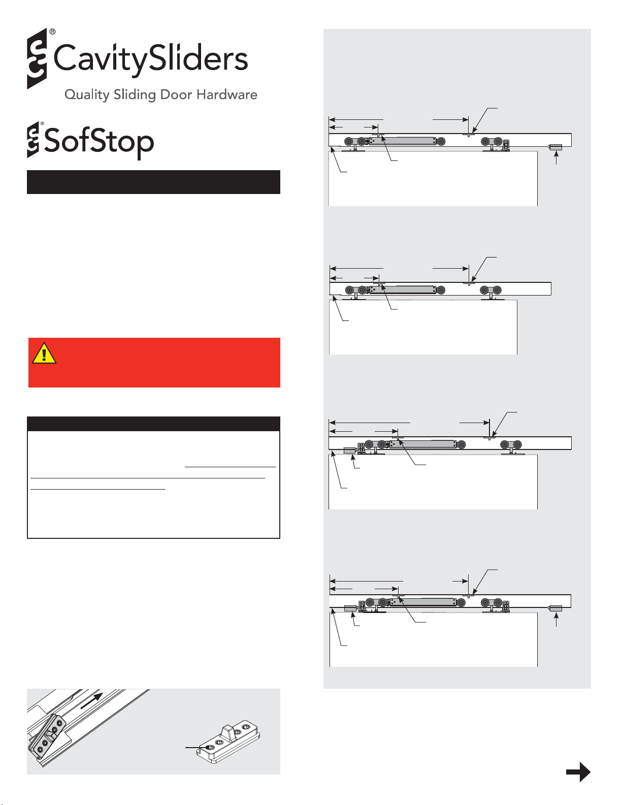
Open the door and loosen the grub screw to allow the Activator to slide freely in the track.
Open the door. Without moving the activator tighten
one
of the four grub screws.
Place the 'Activator Positioning Template' at the end closest to the cavity pocket and mark a line.
ACTIVATOR POSITIONING
1
Twin Action Soft Open & Close
Installation
Instructions
These instructions cover the preparation of doors to be
fitted into a pocket that has the CS SofStop Track fitted.
Read through the notes carefully before beginning as
different mounting plate positions and set-ups may be
required for different configurations.
Ensure rear activator is positioned correctly
in the track BEFORE lining the wall.
READ INSTRUCTIONS BEFORE INSTALL.
A - Rear track stop
11½”
Tra c k
notch
DW + 20¾”
Front
activator
B - No track stops
DW + 20¾”
11½”
Front
Tra c k
notch
activator
C - Front track stop
PAGE
Rear activator
Tra c k
stop
Door
Rear
activator
Door
IMPORTANT
The CS SofStop carriages require a clean track running
surface free of any contamination or damage.
After installation but before lining, clean the full length
of the inside running surface of the track with a soft
rag, then TAPE UP THE TRACK to ensure no dust or
debris enter the track during building works.
Make sure no dirt, grit or aluminum swarf gets into
the track. This could impair the smooth running of the
carriages.
1 Activator positioning
Before mounting the track in the opening you will
need to insert the front and rear activators into the
track. Use the formula (right) to measure from the
notched end of the track to the center of the activator.
Only tighten one screw on the activator as this
is an approximate position. Final position will be
determined later.
If your door protrudes out of the pocket in the open
position you will need to take this distance away
from the rear activator formula.
(e.g. DW + 20¾” - 4”).
Notched end
of track
Slide ac tivator
into track
Grub
screws
Activator
Rear
13½”
Tra c k s t o p
Tra c k
notch
DW + 22
Front
activator
Door
7
/
”
8
activator
D - Front & rear track stops
Rear
7
13½”
Tra c k s t o p
Tra c k
notch
Note: if the activator position falls over a track mounting
hole, re-drill the mounting hole in a new position. Make
sure you blow out the swarf so it does not impact the
performance of the system.
DW + 22
/
”
8
Front
activator
Door
Go to page 2 (overleaf)
activator
Tra c k
stop
Page 2

2
PAGE
2 Prepare the door(s).
Drill holes in the positions as shown (below).
Screw both mounting plates to the door with
the plunger pins facing towards the edges of the
door. Make sure they are placed exactly in the
center of the door thickness.
At the bottom of the door, cut a groove to the
dimension and tolerance shown. Make it central
of the door thickness and absolutely straight.
SUGGESTED
T-GUIDE
PLACEMENT
Pocket framing
T-Gu ide
Casings
Door
PREPARING DOORS
- Without Stops
Mounting
plate
85mm (3-3/ 8”)
to center of
boss hole
5-5.5mm
(1/4”)
20-21mm (13 /16”)
PREPARING DOORS - With Stops
Black
plastic
Tra c k
stop
stop
Fit screws
as shown
Plunger pin
Drill ø25mm (1”)
13mm (1/2”)
deep
4 Install the SofStop mechanism.
If the pocket frame has been supplied with head jambs
fitted, remove the jamb from one side to allow access to
carriages for mounting and vertical height adjustment.
Re-fix the head jamb once door has been mounted and
desired door clearance is achieved.
Lintel
approx. 3/8” clearance
Head
top
Timber
pelmet
block
Clearance 3/8”-13/16”
(adjustable)
Head jamb
Screw fix pocket
header into lintel/
stud when using
heavy doors
1 3/8”
Head
jamb
Fix after door
installation
The mechanism fits together as shown (top of page 3).
The activators should already be in the track. If they are
not, follow instruction 1 on Page 1.
mechanism into the track:
To load the SofStop mechanism into the track:
a) Insert the rear carriage in from the notched end of the
track. Note: Rear carriage does not have a tow bar.
To load the SofStop
Drill ø25mm (1”)
13mm (1/2”)
deep
150mm (6”) to
center of boss
hole
T-Gu i d e
20-21mm
(13/16”)
5-5.5mm (1/4”)
3 Fix the T-Guide.
Fix the T-Guide to the floor so that it is not visible when
the door is in the pocket. The front edge of the T-Guide
should sit flush with the final casings.
Notched
end of
track
Rear carriage
b) Insert the cassette into the notched end of the track,
dolly wheel first, ensuring that the pickup mechanism is
facing up.
2
1
SofStop
cassette
Page 3
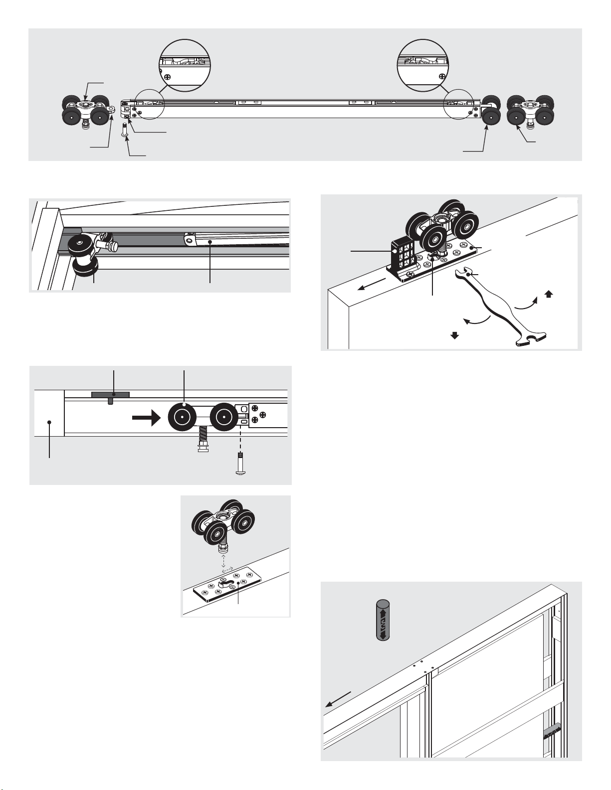
SOFSTOP TWIN
MECHANISM
Front
carriage
Tow b a r
Front pickup
mechanism
(in charged position)
Tow bar receiver
M5 pan head machine screw
Rear pickup
mechanism
(in charged position)
Dolly wheel
3
PAGE
Rear
carriage
4 c) Slide the front carriage into the track with the tow bar
facing into the pocket.
Front carriage SofStop cassette
d) Before fixing the carriage to the cassette, make sure it
has been pushed past the activator. Failure to do so will
damage the pickup mechanism.
Secure the carriage to the cassette with the M5 pan head
machine screw. Tighten with a # 2 Phillips drive.
Activator Carriage
Slide carriage
past activator
Notched end
of track
M5 pan head
machine screw
5 Hang the door(s).
Position the carriages in the
pocket opening approximately
where the mounting plates
on the door will be located
when the door is in the closed
position.
Slide the door over the T Guide
and into the pocket.
Align the mounting plates
with the hanger bolts of the
carriages.
Raise the door up so that the round head of the wheel
hanger shaft lines up with the keyhole shaped hole in the
mounting plate.
Depress the plunger using the wheel hanger shaft head
and slide sideways until it snaps into locked position.
Repeat for the other carriage.
Mounting
plate
6 Adjust the door height.
When adjusting door height, the wrench should be
horizontal to the nut.
Use the small end of the wrench supplied to rotate the
hexagonal nut at the bottom of the carriage hanger shaft.
6 To raise door: Rotate wrench from left to right.
To lower door: Rotate wrench from right to left.
Black plastic stop
(Bi-Parting
units)
Tap this way
to remove
Plunger
pin
Note: The top of the hanger shaft screws into a self-
locking nut. If the hexagonal nut is turned counter
clockwise too far, the shaft will become loose from the
self-locking nut. If the turning resistance suddenly feels
much easier, you have gone too far.
Mounting
plate
Adjusting
wrench
To lower
door
To raise
door
Club end
of wrench
If you raise the door to the maximum height position,
the threaded bolt may contact fixing screw heads. If
required, remove hanger bolt from wheel and remove
2-3mm (1/8”) of thread.
7 Set final activator positions.
a) Loosen the grub screw of the rear activator. Slide it
approximately 2” towards the track notch.
b) Hold the activator setting block inside the back stud and
gently open the door onto it. The activator will slide
along the track into the correct position.
c) Close the door and remove the activator setting block.
Without moving the activator, tighten all four grub
screws.
Activator
setting
block
Pocket
Tra c k
notch
Door
Page 4
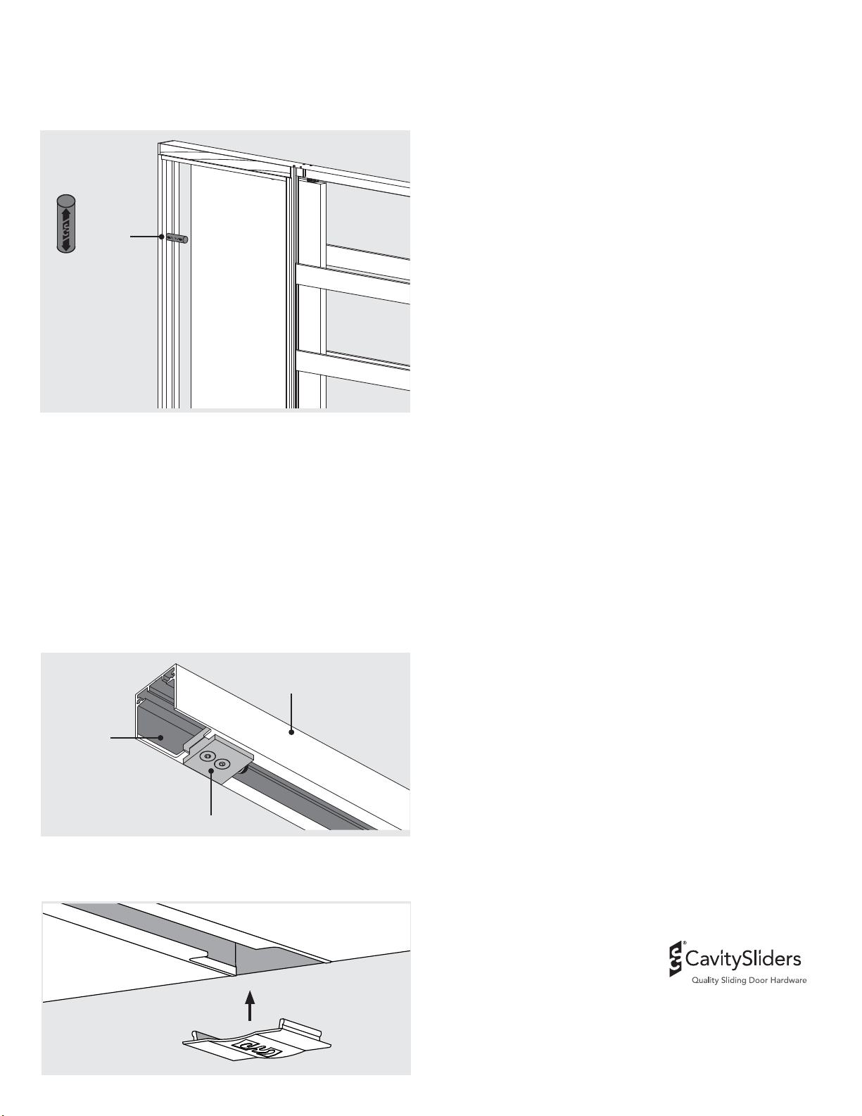
d) Loosen the grub screw of the front activator
(currently in the temporary position). Move it
4
PAGE
f) Open the door and remove the activator setting block.
Without moving the activator, tighten all four grub
screws. The activators are now positioned.
Note: Some doors may still bump on the closing jamb
when closing. If this is a concern, a 3M clear dome stop
(or similar) can be used.
approximately 2” towards the pocket.
e) Hold the activator setting block inside the closing
jamb and gently close the door onto it.
Activator
setting
block
Door
10
Removing the door(s) (for painting, repairs etc).
Fit the club end of the adjusting wrench over the
hexagonal nut at the bottom of the hanger pin.
Use the extended part of the wrench to press down the
plunger pin that protrudes up from the mounting plate.
Once this plunger is fully depressed slide the wrench
sideways towards the plunger pin.
The whole carriage (including the shaft) will now
disengage from the mounting plate.
It is not always easy to slide the wrench sideways.
You may need to relieve the door’s weight by put ting a
wedge between door and floor.
Mounting plates with stops: Remove the black plastic
stop that is tightly fitted into the mounting plate by
tapping it out in the direction shown using a hammer and
drift.
8 Track stops.
Slide the track stop into the track via the carriage
removal notch and loosely tighten so that the track stop
is still able to slide.
Use the door to push the track stop to where you
want the door to stop. Slide the door away and
tighten the track stops using a hex key.
Tra c k
Carriage
removal
notch
Tra c k s t o p
9 Insert the track notch cover
if required.
Cavity Sliders USA Inc.
548 Finney Ct, Gardena, CA 90248
Phone: (888) 466 0030
Fax: (310) 769 5824
Another quality product from:
[email protected]
www.cavitysliders.com
© All copyright and other property in this document is reserved by Cavity Sliders USA Inc.
Details and specifications are subject to change without notice. Whilst all care is taken to ensure
the accuracy of all information, no responsibility will be accepted for any errors or omissions.
CS SOFSTOP™ (O.D. 2012). 10.2018 - ZNI125 / 60721/US
© Cavity Sliders USA Inc. Drawings are not to scale.
 Loading...