

Page 1

ASSEMBLY INSTRUCTIONS
[ REV001]
Instructions by O.Kolly & S.Caviglioli 27.10.2016
SEQ-UFD V1 - www.cavisynth.com – 2016 S.Caviglioli 1
Page 2
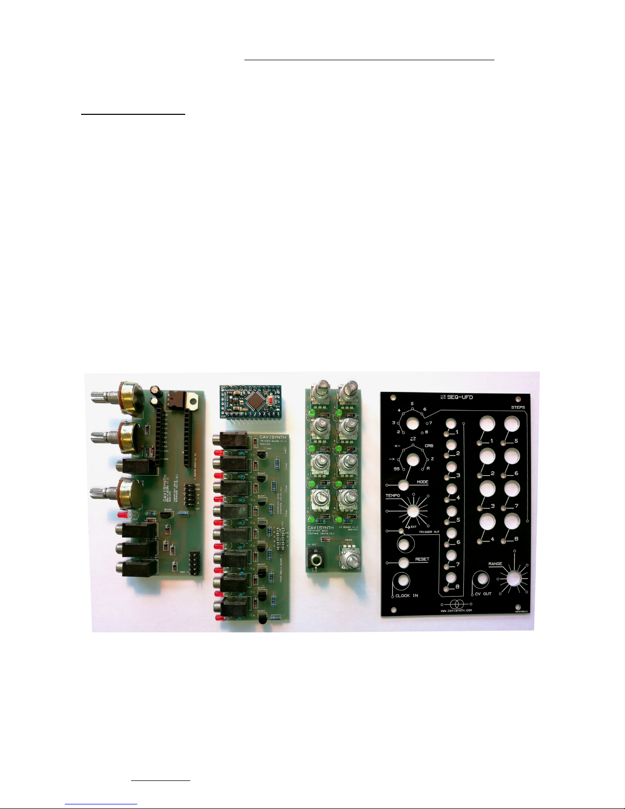
First, make sure you have in your possession all the necessary parts and components.
For this, refer to the boom file : http://cavisynth.com/product/seq-ufd/#downloads
You will also need:
• A soldering iron
• Welding wire
• A fine forceps
• The side cutter
• Stripper's son
• A dry and clear work plan
• Between 3 and 4 hours for construction
In the phicture below, you can see every part before final assembly.
It consists of 3 boards (brain, trigger, CV) ProMini a board and a front panel.
So... let's go !!!
SEQ-UFD V1 - www.cavisynth.com – 2016 S.Caviglioli 2
Page 3
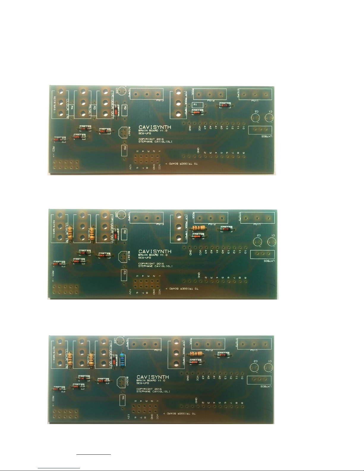
A. BRAIN BOARD
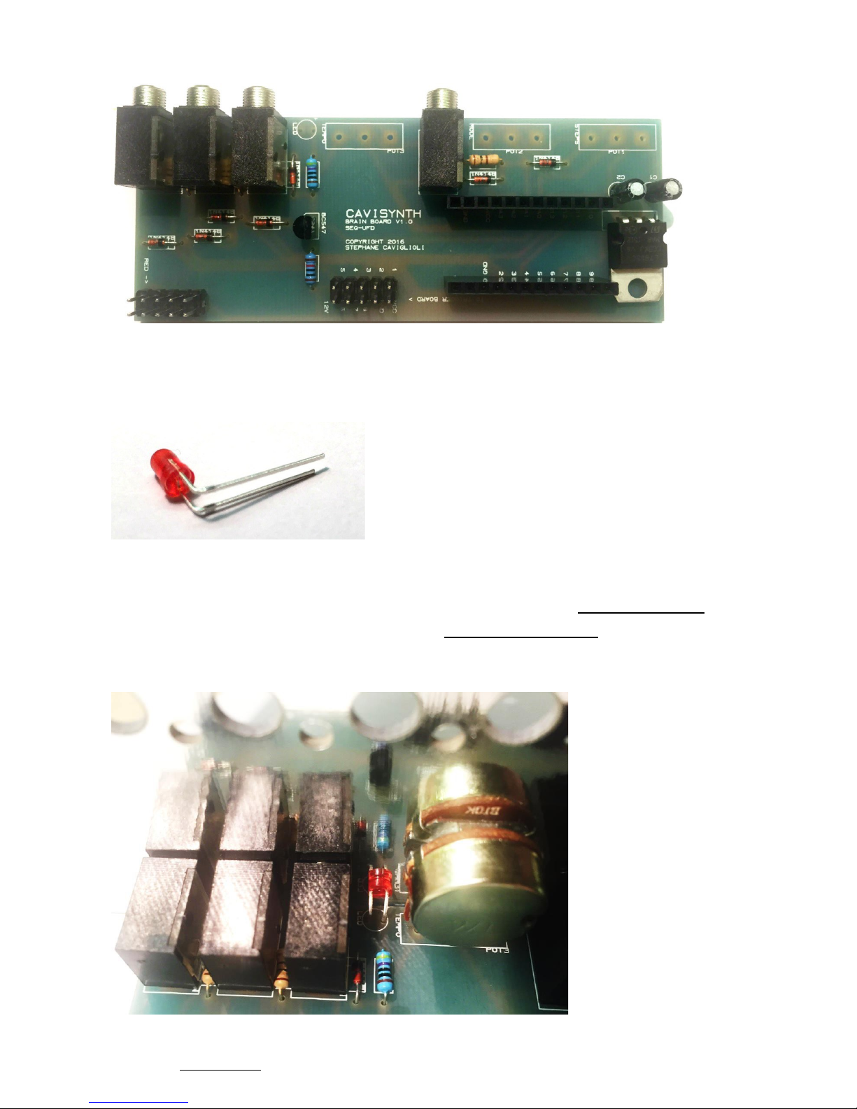
Solder 8 x 1N4148 diode.
These parts have a specific orientation and they need to go in the right direction.
White line on the board corresponds to the black line on the diode.
Solder 3 x 100[Ohm] resistor on R1, R3, R4.
Solder 1 x 470[Ohm] resistor on R2.
SEQ-UFD V1 - www.cavisynth.com – 2016 S.Caviglioli 3
Page 4
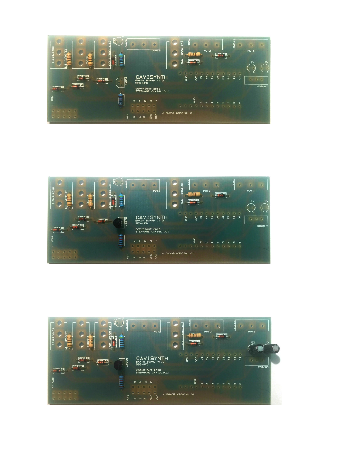
Solder 1 x 10[KOhm] resistor on R5.
Solder 1 x BC547 transistor.
The shape of the transistor have to be the same of silkscreen.
Solder 2 x 10[uF] capacitor on C1, C2.
These parts are polarised, negative (short leg) goes in the ( - )
SEQ-UFD V1 - www.cavisynth.com – 2016 S.Caviglioli 4
Page 5
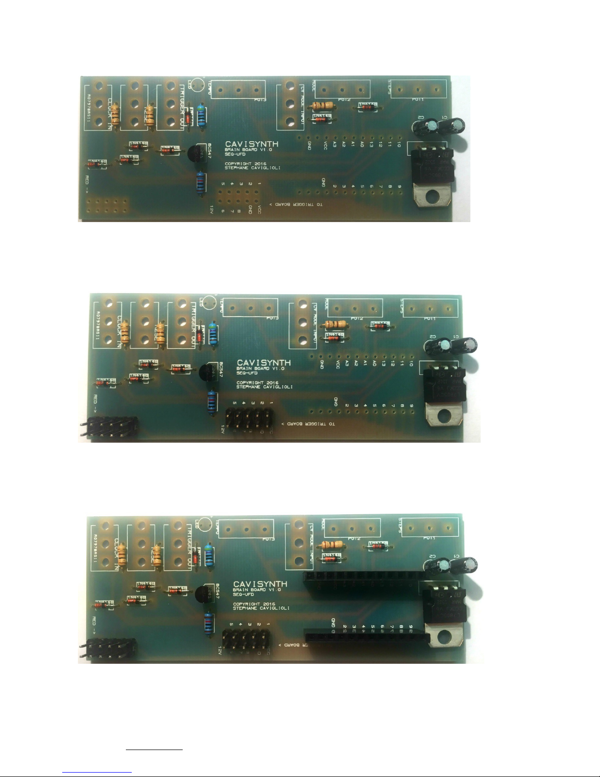
Solder 1 x LM7805 5[V] regulator.
You can fold it or leave it standing but bend the front legs of the weld.
Solder 2 x 10 pin double male header.
Solder 2 x 12 pin single female header.
SEQ-UFD V1 - www.cavisynth.com – 2016 S.Caviglioli 5
Page 6
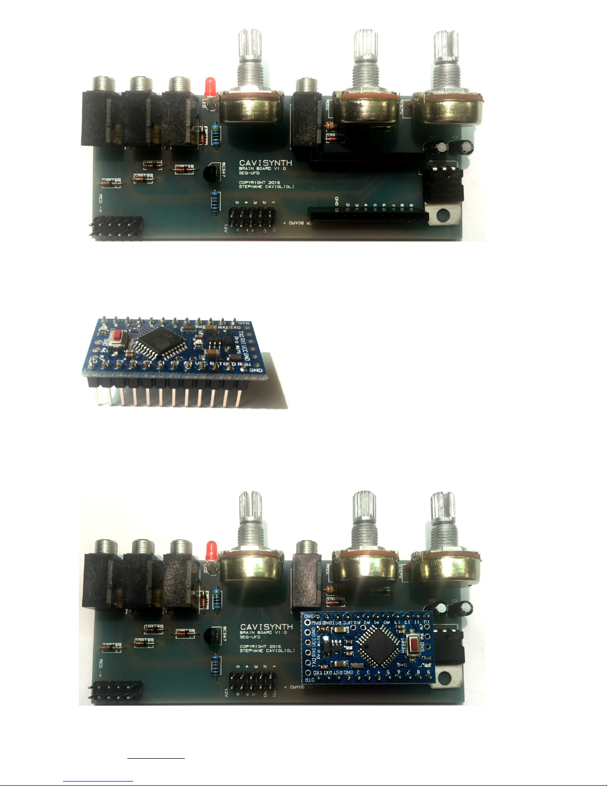
Solder 4 x Jack plug.
Take one red led and fold it as the picture below.
Place the led. Leds are polarized, positive (long leg) goes in the +. Don’t solder it yet.
Place 3 x pot PR10KB on POT1, POT2, POT3. Don’t solder them yet.
Mount the panel and push the led inside the hole at the maximum as the picture below.
Solder the pots and the led.
SEQ-UFD V1 - www.cavisynth.com – 2016 S.Caviglioli 6
Page 7
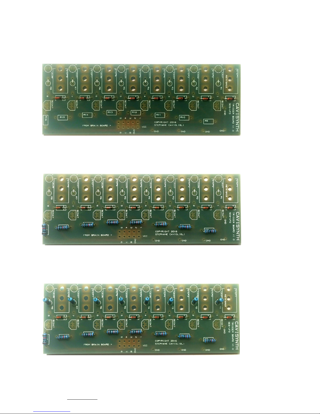
Solder 2 x 12 pin single mal header on the PROMINI board.
Place the PROMINI in the right direction.
SEQ-UFD V1 - www.cavisynth.com – 2016 S.Caviglioli 7
Page 8
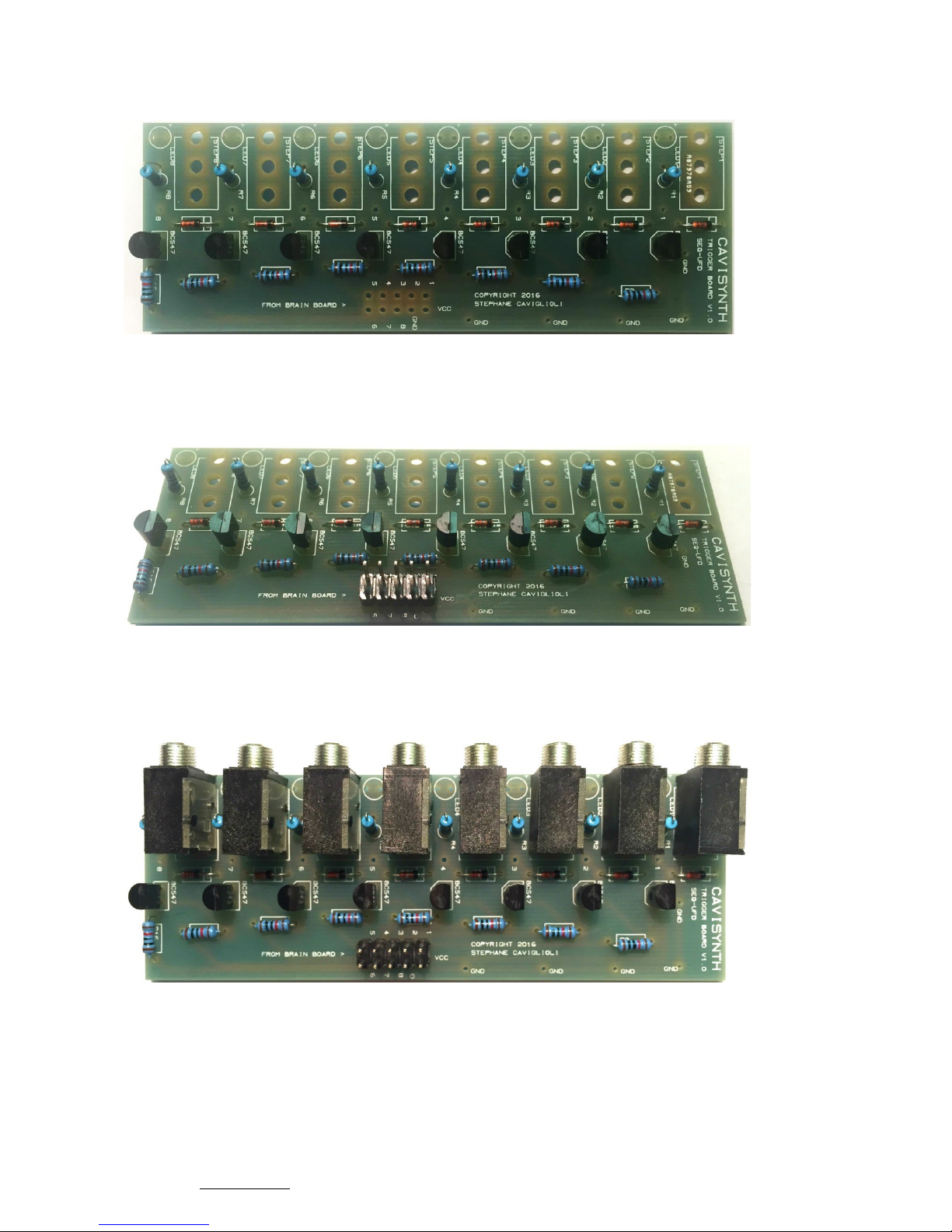
B. TRIGGER BOARD
Solder 8 x 1N4148 diode. Again, these parts have a specific orientation and they need to
go in the right direction.White line on the board corresponds to the black line on the diode.
Solder 8 x 10[KOhm] resistor on R9 to R16.
Solder 8 x 470[Ohm] resistor on R1 to R8.
SEQ-UFD V1 - www.cavisynth.com – 2016 S.Caviglioli 8
Page 9
Solder 8 x BC547 transistor.
The shape of the transistor have to be the same of silksscreen.
Solder 1 x 10 pin double male header.
Solder 8 x Jack plug.
SEQ-UFD V1 - www.cavisynth.com – 2016 S.Caviglioli 9
Page 10
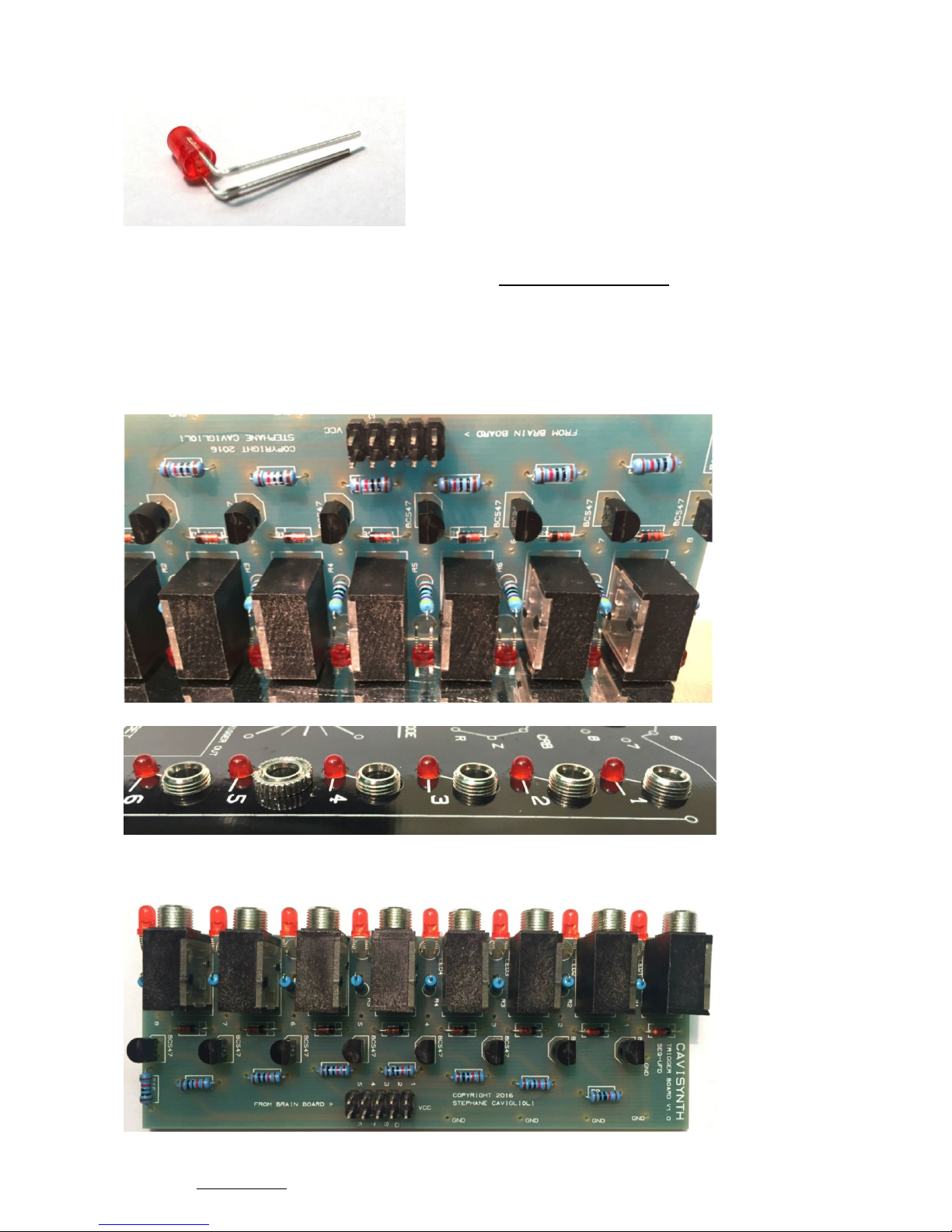
Take 8x red led and fold them as the picture below.
Place the leds. Positive (long leg) goes in the +. Don’t solder them yet.
Mount the panel and push the leds inside the holes at the maximum, as the picture below.
Solder the leds.
Now you can solder the red leds.
SEQ-UFD V1 - www.cavisynth.com – 2016 S.Caviglioli 10
Page 11
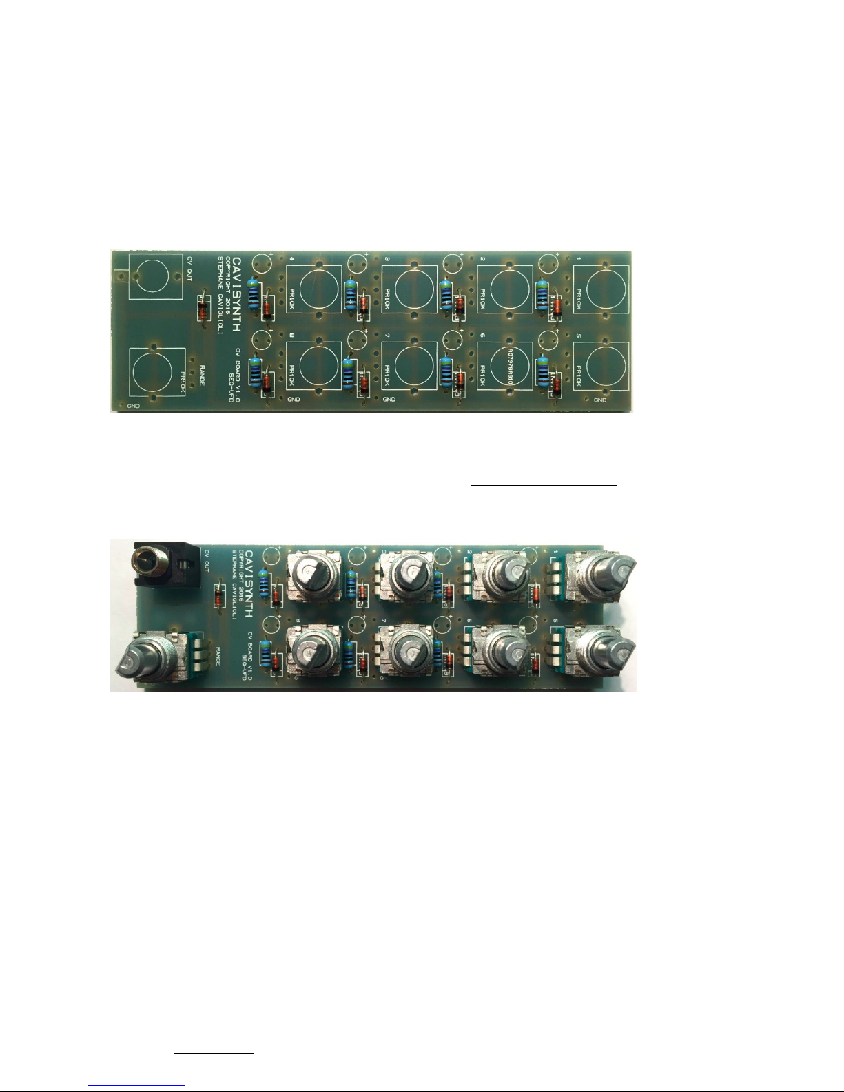
C. CV BOARD
Solder 8 x 1N4148 diode. Once again, these parts have a specific orientation and they
need to go in the right direction.White line on the board corresponds to the black line on
the diode.
Solder 8 x 470[Ohm] resistor on R1 to R8.
Place 9 x PR10KB9 pot and 1 x vertical jack plug. Don’t solder them yet.
Mount the panel, aim a few pots, then solder pots and jack.
SEQ-UFD V1 - www.cavisynth.com – 2016 S.Caviglioli 11
Page 12
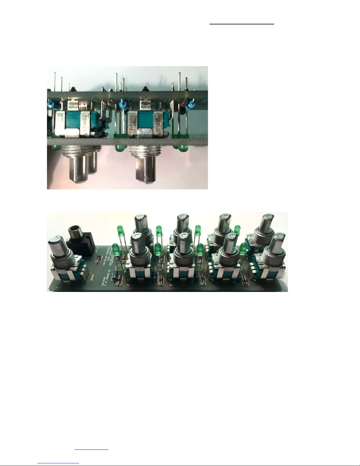
Place 8 x green leds. Positive (long leg) goes in the +. Don’t solder them yet.
Again, mount the panel, aim a few pots, then push all leds in holes at the maximum, as the
picture below.
Solder all green leds.
SEQ-UFD V1 - www.cavisynth.com – 2016 S.Caviglioli 12
Page 13
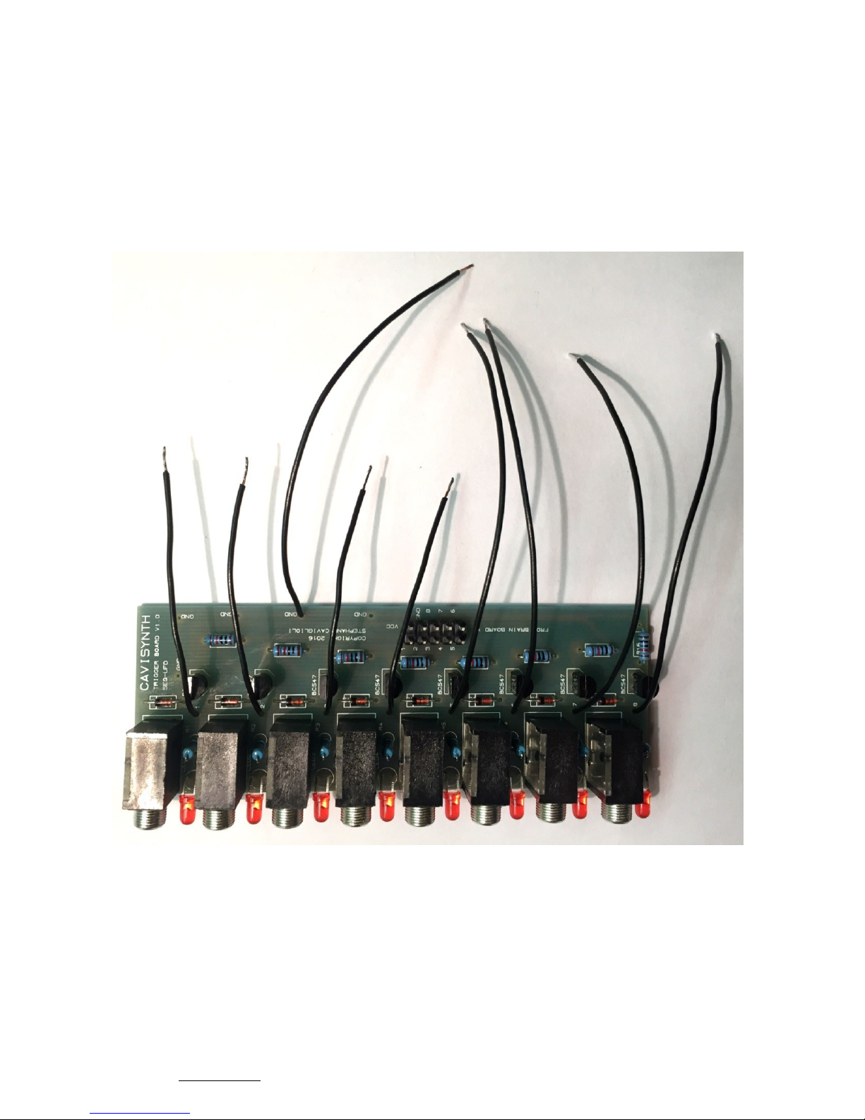
D. GENERAL
Prepare (stripping and tinning) 4 x 6[cm] wire and 5 x 10[cm] wire.
Solder 4 x 6[cm] wire on numbers 1 to 4.
Solder 4 x 10[cm] wire on numbers 5 to 8.
Solder 1 x 10[cm] wire on GND.
SEQ-UFD V1 - www.cavisynth.com – 2016 S.Caviglioli 13
Page 14
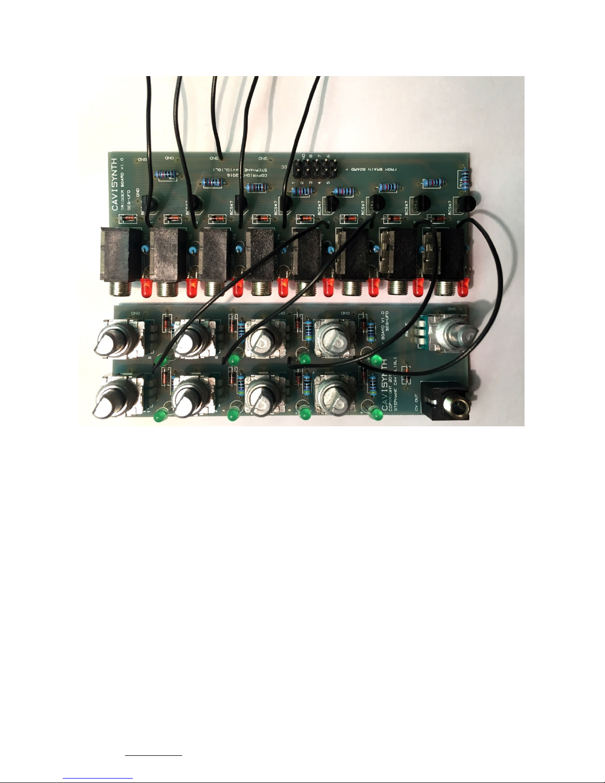
Solder 4 x 10[cm] wire on numbers 5 to 8 of CV BOARD.
TRIGGER BOARD to CV BOARD : numbers 5 to 5, 6 to 6, 7 to 7, 8 to 8.
SEQ-UFD V1 - www.cavisynth.com – 2016 S.Caviglioli 14
Page 15
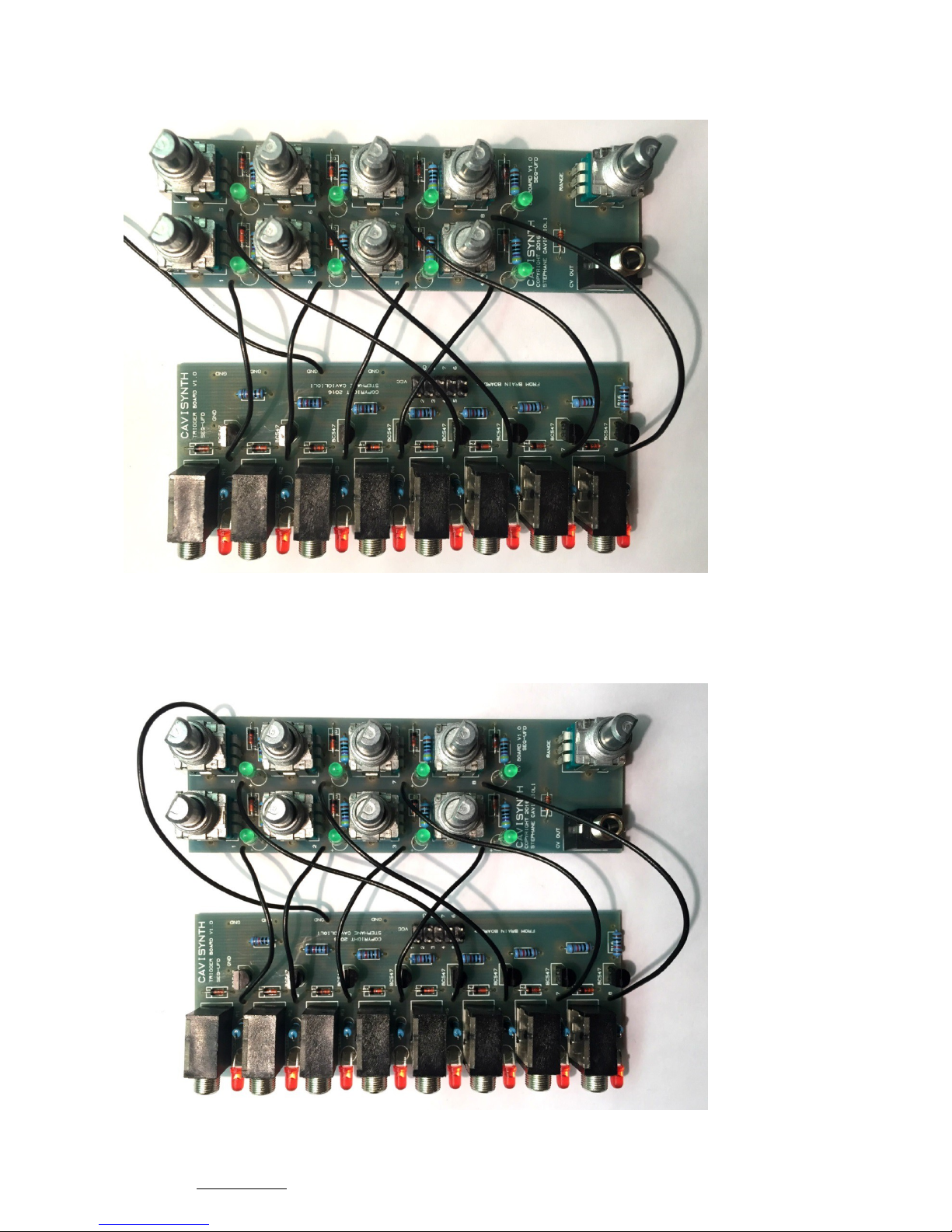
Solder 4 x 6[cm] wire on numbers 1 to 4 of CV BOARD.
TRIGGER BOARD to CV BOARD : numbers 1 to 1, 2 to 2, 3 to 3, 4 to 4.
Solder 1 x 10[cm] wire on GND of CV BOARD.
SEQ-UFD V1 - www.cavisynth.com – 2016 S.Caviglioli 15
Page 16
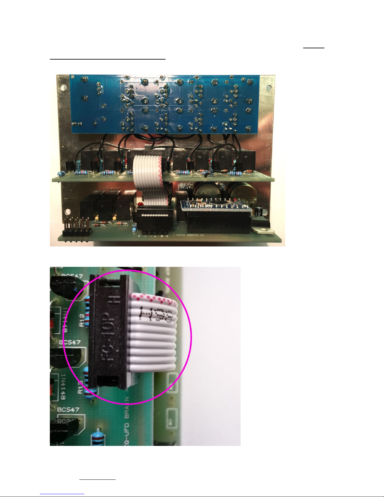
Mount the boards on the panel and connect BRAIN BOARD to TRIGGER BOARD with the
6[cm] ribbon.
Pay attention to the red strip and follow the direction as the picture below ( VERY
IMPORTANT : RED STRIP TOP !!! )
Close up view of 6[cm] ribbon between brain & trigger board
SEQ-UFD V1 - www.cavisynth.com – 2016 S.Caviglioli 16
Page 17
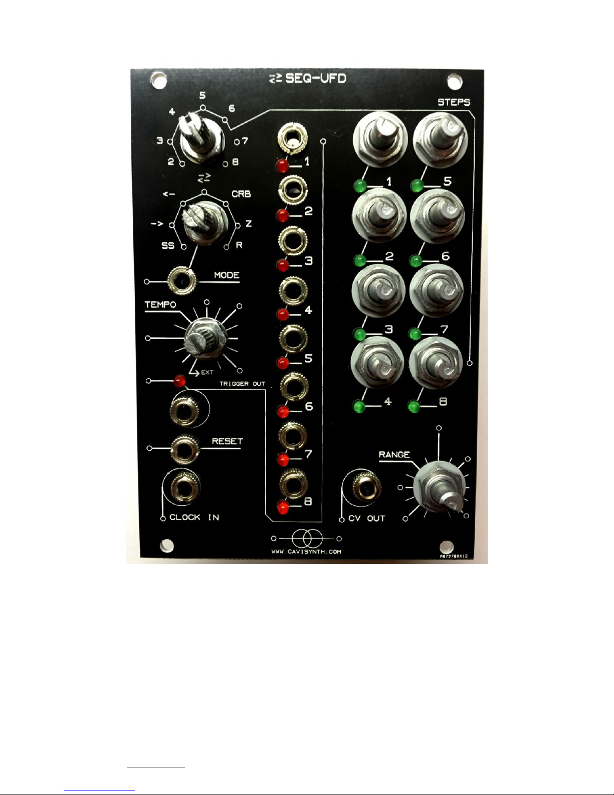
Place all the washers and the nuts
SEQ-UFD V1 - www.cavisynth.com – 2016 S.Caviglioli 17
Page 18
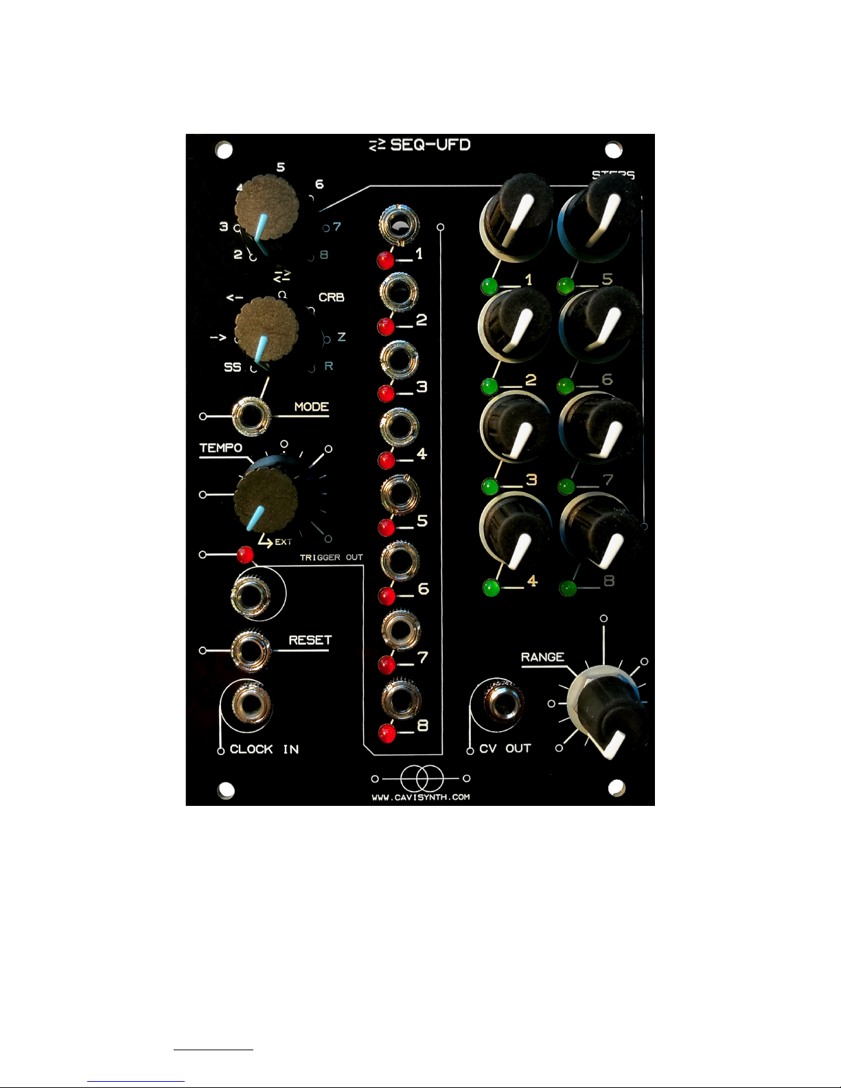
Place the knobs.
Notice : the range knob is inverted compared to CV knobs.
SEQ-UFD V1 - www.cavisynth.com – 2016 S.Caviglioli 18
Page 19
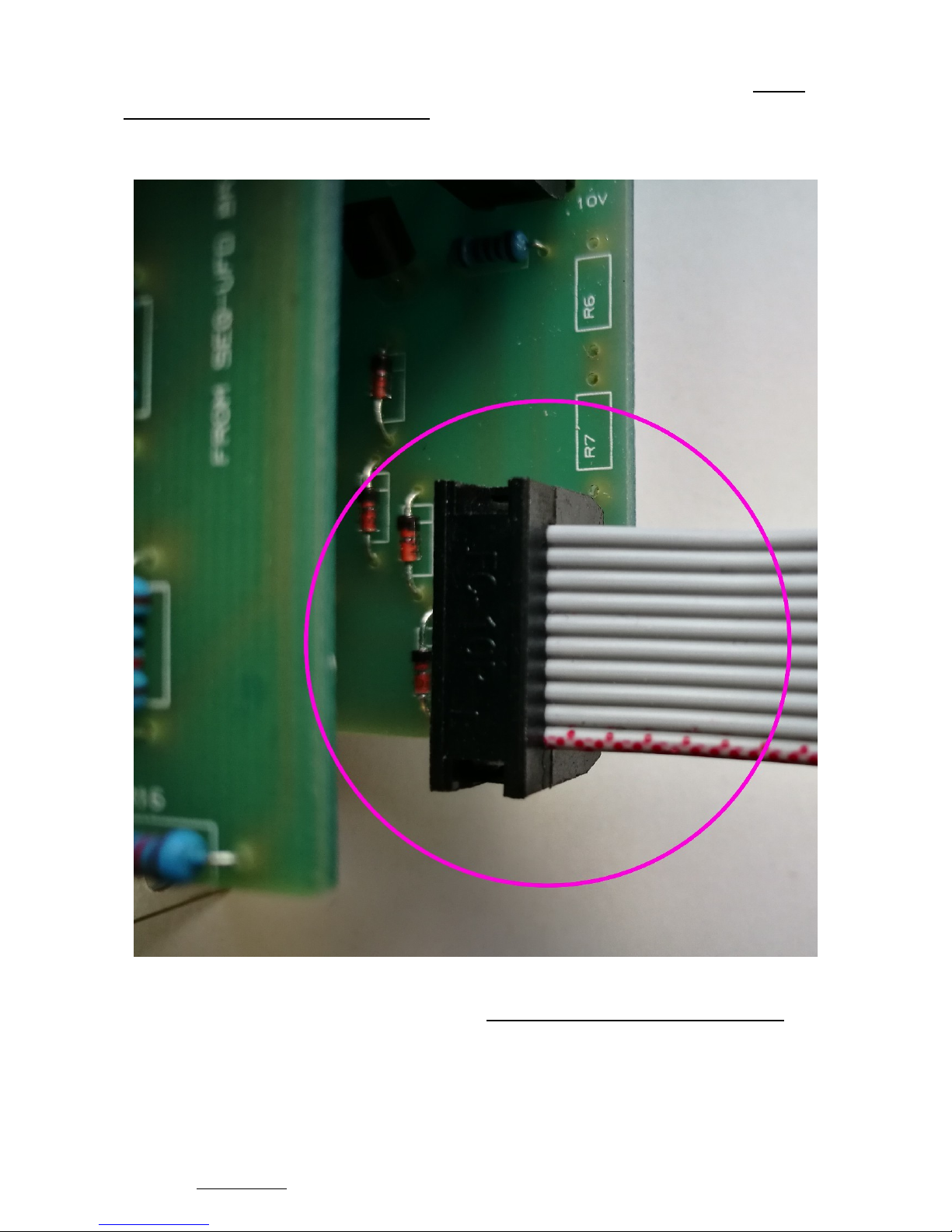
Place the 20[cm] power ribbon.
Pay attention to the red strip and follow the direction as the picture below ( VERY
IMPORTANT : RED STRIP DOWN !!! )
Close up view of 20[cm] power ribbon
ATTENTION : Make sure that the red strip orientation is the correct one, otherwise it
could cause severe damage to the module. Cavisynth decline all responsibility.
Should this happen, please contact us and we will try to find a solution.
Now you can test it. No settings, no callibration. It's ready !
SEQ-UFD V1 - www.cavisynth.com – 2016 S.Caviglioli 19
 Loading...