

Cavidyne, LLC CaviBlaster HG-1222 Operating Instructions Manual
OPERATING INSTRUCTIONS
WARNING: To ensure operator safety and efficient operation of the Cavi-
BlasterTM system, it is essential to follow these instructions.
Preparing the CaviBlasterTM system for operation:
1. Inspect the CaviBlasterTM power unit, hoses and lance for any signs of damage.
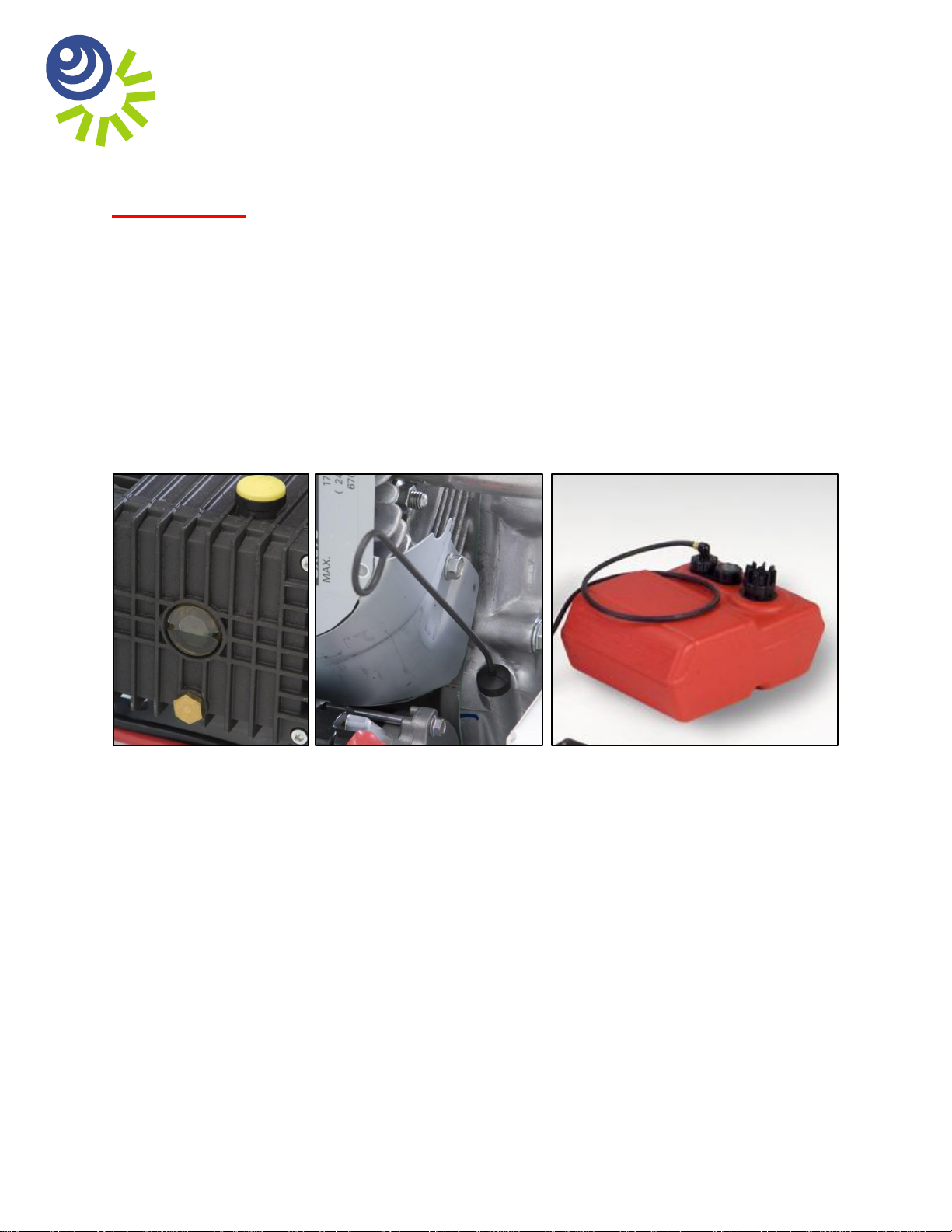
2. Check oil and fuel levels:
Proper oil level in pressure pump (Figure 1) and engine (Figure 2).
Gasoline level in detachable fuel tank (Figure 3).
Figure 1 Figure 2 Figure 3
3. Fill lubricating oil(s) to proper level(s) as necessary and per pressure pump and engine
manufacturers’ operating manuals.
4. When feeding water to the CaviBlasterTM power unit with the feed pump, connect the 1”
diameter clear PVC feed hose to the brass cam-lock plug on the pressure pump inlet (Figure
4). The feed hose has the feed pump on one end and a brass female cam-lock on the other
end. Insert the electrical plug powering the feed pump into the waterproof electrical outlet on
the end of the power unit cart under the handle (Figure 5). Ensure that the red knob on the
plug is facing up and mates with the notch in the outlet cover. If the plug is engaged upside
down, the pump will turn in reverse. Ensure that the feed hose is connected to the pressure
pump and that the feed pump is securely submerged in the water source prior to starting the
pump. Either fresh water or seawater can be used with this system.
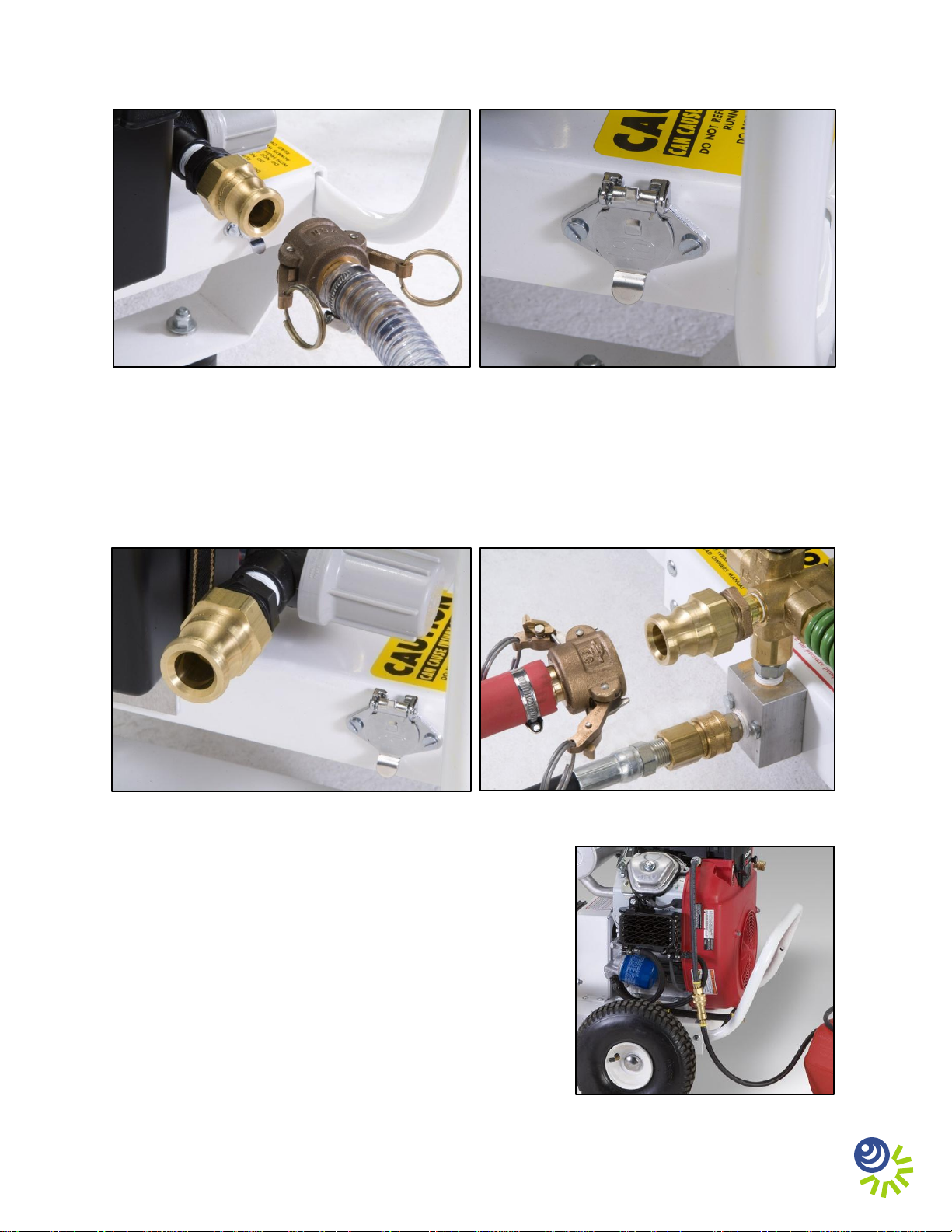
Figure 4 Figure 5
When feeding the CaviBlasterTM with an alternate water source, the source must supply water
at a volume of greater than 12 gallons per minute at a maximum pressure of 70-psi. Connect
the water source to the inlet of the pressure pump (Figure 6). Ensure that the feed hose is
connected to the pressure pump and the water is on prior to starting the pressure pump.
Figure 6 Figure 7
5. Connect the 1” red rubber bypass hose to the brass
cam-lock plug on the pressure-regulating unloader
(Figure 7). The hose has a brass female cam-lock
on one end. Direct the bypass hose away from the
working area and secure the hose.
Figure 7
6. Connect the ¼” black rubber fuel line from the
external fuel tank to the fuel line attached to the
fuel filter and engine. This connection is made
with a brass quick connect fitting (Figure 8).
Figure 8
2
 Loading...