


Service Manual for Cavecool
Single zone model#CC34SB&CC62SB&CC102SB
Dual one model#CC29DB&CC54DB&CC102DB
CC34SB
CC29DB
CC62SB
CC54DB
CC102SB
CC102DB

The following lists the bar in the course of various failures that may occur,aswellastofindandfix
these faults. Please corresponds fault item and then find the corresponding page number information.
Maintenance Preparing:
○Tools
1.Vise 2. Cross screwdriver 3.goggles 4.Clamp Meter 5. Multimeter
(5A)
5
Wrench 6.Electric iron 7.Strippers 8.Sealing jaws 10. The protective gloves
.
○ Equipment
1.Vac u um p u mp
2
Soldering equipment 3. Pressure gauge / refrigerant metering device
.

Content
1.Precautions………………………………………………………………4
2.Technical specification………………………………………………5
2.Schematic diagram……………………………………………………6
3. NTC value…………………………………………………………………8
4.Control panel……………………………………………………………10
5.The fault diagnosis……………………………………………………11
Disassembly instruction of main components………………17
6.

1. Repair work safety precautions (please follow below precautions before maintenance)
DANGER
• Do not use open flames indoor or smoke during reqairing.
• Do not perform welding in poorly ventilated and confined areas
• Do not have children nearby when reparing
WAR NI N G
•
Always unplug the power cord first before carrying out maintenance
Otherwise, it may result in electric shock and injuries.
•Please be careful not to get electric shock during reparing.
Unplug the power cord before maintenance. If needs to check the circuit while the
power is on,do not touch the live electrical parts! If electric wires are damaged, it
must be replaced by qualified technician in time.
• Use original parts which shown in the part list, do not use parts from other models
or other brands, never modify the parts
• Use appropriate maintenance tools, improper use of tools may cause insecure
assembly
• If wires are cut during maintenance. Remember to reconnect the wire and seal with
insulating tape
•When discharging the refrigerant, make sure the room is in good ventilation
condition.
•When cutting off the compressor pipes, pay attention to the remaining refrigerant
and internal pressure.
• After maintenance finished, use multimeter to check the insulation, makesurethe
insulation resistance is over 2 MΩ before connecting to power.
•After repair, it is necessary to check whether the grounding is in good condition
4

Be careful to the high temperature of compressor and refrigeration pipes when
product is on or just after the production was power off.
Be careful to the high temperature after soldering
Be careful not to let liquid refrigerant directly touches the skin,it may cause
frostbit
Metal parts and plastic parts burr may scratch the hand.
1.
Technicalspecification
Single zone model
Model no. CC34SB CC62SB CC102SB
NOTICE
Single zone compressor
Product type
Installation Type Free standing only Free standing only Free standing only
Gross / Net Volume 91L / 89L 152L / 148L 247L / 242L
Bottle Loading Capacity 34 bordeaux bottles 62 bordeaux bottles 121 bordeaux bottles
Voltage
&Frequency
Power 90W 90W 100W
Set temperature
Gas refrigerant R600a R600a R600a
Weight of gas 25g 30g 38g
Defrosting type Auto defrost Auto defrost Auto defrost
Climate class SN/N/ST SN/N/ST/T SN/N/ST/T
Product dimension
(W*D*H )
wine cooler
220‐240V / 50Hz 220‐240V / 50Hz 220‐240V / 50Hz
℃~20℃
5
480×430×508 480×565×850
Single zone compressor
wine cooler
℃~20℃
5
Single zone compressor
wine cooler
℃~20℃
5
550×565×1277
5

Dual zone model:
Model no. CC29DB CC54DB CC102DB
Dual zone compressor
Product name
Installation Type Free standing only Free standing only Free standing only
Gross / Net Volume 85L / 80L 142L / 138L 240L / 232L
Bottle Loading Capacity 34 bordeaux bottles 62 bordeaux bottles 102 bordeaux bottles
Voltage
&Frequency
Power 90W 90W 100W
Tem p era t ure
Setting
Gas refrigerant R600a R600a R600a
Weight of gas 22g 22g 22g
Defrosting type
Climate class N/ST SN/N/ST SN/N/ST
Product dimension
(W*D*H )
wine cooler
220‐240V / 50Hz 220‐240V / 50Hz 220‐240V / 50Hz
Upper: 5
Lower:12
℃~12℃
℃~18℃
Auto defrost
480×430×508 480×565×850
Dual zone compressor
wine cooler
Upper: 5
Lower:12
℃~12℃
℃~18℃
Auto defrost Auto defrost
Dual zone compressor
Upper: 5
Lower:12
550×565×1277
wine cooler
℃~12℃
℃~18℃
2.
Schematic diagram
2.1.Single zone model
6

2.2 Dual zone model
、
3. Cooling system schematic diagram:
3.Cooling system schematic diagram:
2.3 Cooling system schematic diagram:
7

3.NTC value
8
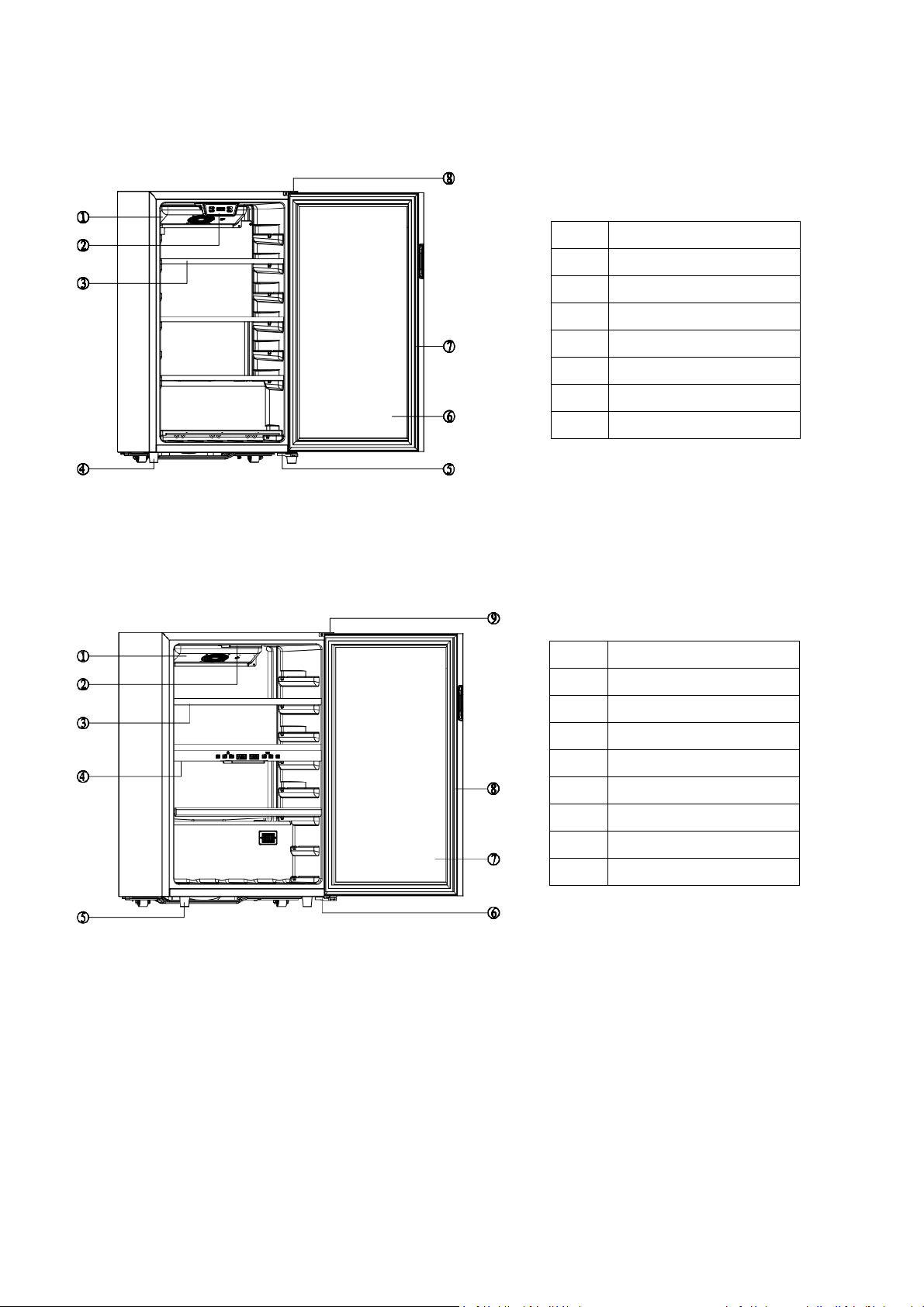
4.Structure diagram
4.1 Single zone model
1
Fan
2 Control panel and LED light
3
Shelf
4
Feet
5 Lower hinge
6
Door
7
Gasket
8 Upper hinge
4.2 Dual zone model
1
Fan
2
LED light
3 Shelf
4
Control panel
5
Feet
6 Lower hinge
7
Door
8
Gasket
9 Upper hinge
9

5.Control Panel
5.1 Single zone model
13
24
Temperature range is 5‐20°C.
‐ 1. Press ON/OFF button to turn on the appliance, and press ON/OFF for 3 seconds to turn off the appliance.
‐ 2. Press LIGHT button to turn on or turn off the light
‐3.Press UP button to increase the setting temepreture
‐4.Press down button to decrease the setting temepreture
Press temperature control button “UP” and “DOWN” together for 3 seconds to change the LED display from
Celsius to Fahrenheit
Important note: After selecting the desired temperature, the display will continue to show the real
temperature inside the equipment, which will vary gradually until it reaches the selected temperature.
5.2 Dual zone model
Temperature range for upper zone is 5‐12°Candforlowerzoneis12‐18°C.
Press power switch button for 3 seconds to turn on or turn off the appliance
-
Press light button to turn on or turn off the light in both zones
-
10

Press lower zone temperature contol button and together for 3 seconds to change the LED
r
r
-
display from Celsius to Fahrenheit.
You can set the desired temperature by pressing or of each zone
-
The temperature selected will increase/decrease by 1°C with each press of the buttons.
Notice: Important note: after selecting the desired temperature, the display will continue to show the real
temperature inside the equipment, which will vary gradually until it reaches the selected temperature.
6.The fault diagnosis
6.1 List of self-diagnostic code (Single Zone)
Code Content Description
E1
L1
HOO
LOO
Temperature sensor
short-circuit fault
Temperature sensor
open-circuit fault
High temperature
alrm
Low temperature
alrm
Check the wire connection of the temperature
sensor socket and connection to the main PCB
Check the wire connection of the temperature
senso
socket and connection to the main PCB
When inside temperature is higher than 25°C
and over 6 hours,it will display “HOO” and
compressor stop working
When inside temperature is lower than 2° C
and over 6 hours,it will display “LOO” and
compressor stop working
6.2 List of self-diagnostic code(Dual Zone)
Code Content Description
E1
L1
F1
F2
HOO
LOO
Temperature sensor
short-circuit fault
Temperature sensor
open-circuit fault
Upper zone
faninopencircuit
Lower zone
faninopencircuit
High temperature
alrm
Low temperature
alrm
Check the wire connection of the temperature
sensor socket and connection to the main PCB
Check the wire connection of the temperature
senso
socket and connection to the main PCB
Check the connection of the upper fan socket
and connection to the PCB
Check the connection of the lower fan socket
and connection to the PCB
When inside temperature is higher than 25°C
and over 6 hours,it will display “HOO” and
compressor stop working
When inside temperature is lower than 2° C
and over 6 hours,it will display “LOO” and
compressor stop working
Processing opinion
For short-circuit,to replace a new
part.
For open circuit,check the
connection and re-connect that
part
Check below 5.3 Handling of
common problems and 5.4
Diagnosis of problems
Processing opinion
For short-circuit,to replace a new
part.
For open circuit,check the
connection and re-connect that
part
Check below 5.3 Handling of
common problems and 5.4
Diagnosis of problems
11

6.3 Handling of common problems
l
PROBLEM POSSIBLE CAUSES
Appliance is not cooling Appliance is not plugged in
Applianceis not turned on
Check if voltage of the installation
Check the circuit breaker or if fuse has blown
Appliance is not cold
enough
Check the temperature control setting
Check if ambient temperature is beyond appliance operating temperature
The door is opened too frequently
The door is not closed properly
The door is not sealing properly
Check if wine cooler is exposed to sunlight or therehas a heat source nearby
Insufficient free space around the appliance
Check if too many wine bottles have block the air ventilation hole
The compressor starts
and s tops frequently
The external temperature is high.
A large quantity of bottles has been put into the cellar.
The appliance is opened frequently.
The door is not properly closed.
The cellar has not been correctly set.
LED lights do not operate The appliance is not plugged in
The fuse has blown
LED lights are not broken
The light switch is off
Vibration Check and ensure that the applianceis leve
The appliance makes a
lot of noise
A noise resembling circulating water is produced by the coolant gas and this
is normal.
At the end of a cooling cycle, you can hear the noise of water circulating.
Expansion and contraction of the internal walls may cause a cracking sound.
The appliance is not level
Check if fan is in good condition
The door does not close
properly
The appliance is not level.
The door seal is dirty or damaged.
The shelves are not positioned correctly.
A part of the contents is preventing the door from closing.
LED display is not
working properly
Controlpanelfailed
Power PCB has broken
The appliance is not plugged in
The probe is not working
Condensed water on the
door glass
It’s normal when ambient temperature is too high or ambient humidity is too
high.
13

6.4 Diagnosis of problems
rRep
r
●Screen not display
Is there a display window of the
product?
The simple way (check the power
supply)
Y
Check the display board to see if
there is input voltage?
Y
Display board Broken
N
Test the power (power cord, plugs,
sockets)
N
Check the control board and display
board
●Compressor doesn’t work
Is setting temperature lower
than ambient temperature?
N
Re‐set the
temperature
Does compressor work after
replace the compressor
protector?
Y
N
Check the main power is on and display
works or not?
Y
Defrost or not
N
Check the connectors in the power
PCB box if it is well‐connected
Y
Cut the power,measure the
N
impedance of the compressor
protector if is <1Ω
(at room temperature)
Y
Y
Connect the power, measure whether
the compressor output terminals P1,
P2 on the main PCB have 220V output
to the compressor
N
Measure the impedance of
N
compressor to check if
it can meet the corresponding
Replace the main PCB
impedance standard
Y
N
Replace PTC starte
14
Replace the compres
lace compresso

●Not cooling or not cooling enough:
Compressor work or not?
Y
Setting temperature is
higher than ambient temp.?
N
Refrigerant gas leak
or not?
N
Y
Refer to above situation A
Lower down the setting
temperature
Checking the cooling parts if is
N
blocked?(pipe of evaporator
and condenser)
Y
re‐welding and refill the
Refrigerant gas
15

●Over cooling
Setting temperature is
NTC probe was blocked
by something?
Replace the NTC probe
●.LED light-failure
check the control
panel keys are workable or
not?
N
too low?
Y
N
Y
N
Y
Check whether there is
DC12V power supply
Turn up the setting
temperature
Do not put objects too
close to NTC probe
Check the light wire is
well connected?
Y
Y
N
Replace the light components
Positive and negative
power supply is reversed?
Ambient temperature
is too low
N
Replace the
control PCB
N
The connector is loose?
otherwise replace the main
circuit board
16
Y
Reconnect positive
and negative wire

7.Disassembly instruction of main components
Turn off and unplug the appliance before replacing the parts to ensure safety operation
7.1.Control PCB & LED light for single zone
1)Unscrew the two bolts,then take off the control panel box and LED light cover.
2) Pull off the wire connectors and then can replace the control PCB and LED light board
12
7.2.Control PCB & LED light for dual zone model
7.2.1 Control PCB
1)Unscrew the 4 bolts on the control panel box.
17

Unscrew the 4 bolts on the
control panel box.
2)Take off the control panel box and the wire connector,then can replace thenewcontrolPCB
7.2.2 LED light
1) Remove the screws and and take off the light cover,then replace the new LED light board.
Fan&NTC probe
18

7.3.Fan&NTC probe
7.3.1 Single zone
Fan
NTC probe
19
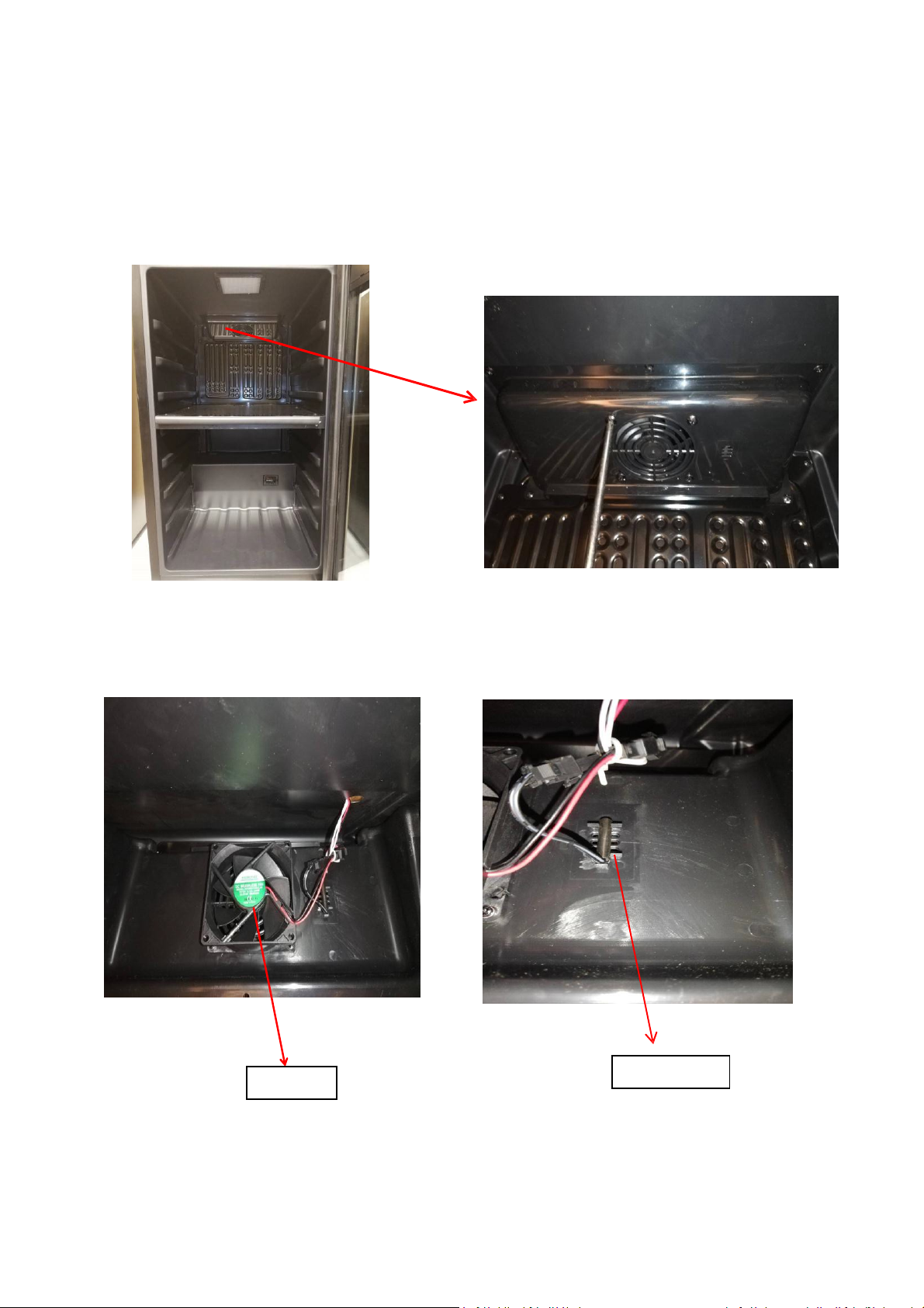
7.3.2 Dual zone
Upper zone fan&NTC probe
Remove the fan mask,and then can replace the fan and NTC probe.
FAN
20
NTC probe
NTC probe

7.4Lower zone NTC probe
7.5Lower zone fan & LED light
Unscrews and remove upper &front cover of the separation zone
Remove the foam in the separation zone,then can replace the fan and LED light.
LOWER ZONE FAN
LOWER ZONE LED LIGHT
Lower zone LED light
21

7.6POWER PCB
1) Removethescrews,andtakeouttheelectricboxcover
22
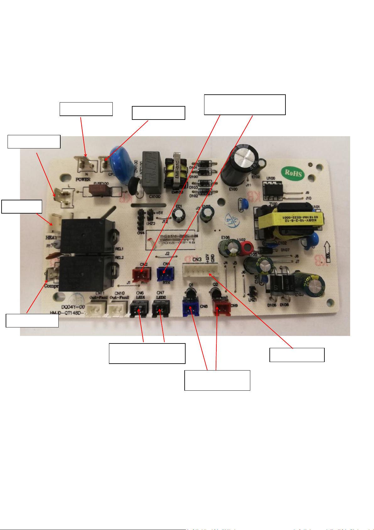
POWER PCB
L:L wire of plug
CN5:Heater
N:N wire of plug
CP3:Compressor
RT1:Upper zone NTC probe
RT2:Lower zone NTC probe
CP4:Compressor
CN6:Upper zone LED light
CN7:Lower zone LED light
23
CN3: Control PCB
CN8:Upper zone fan
CN9:Lower zone fan
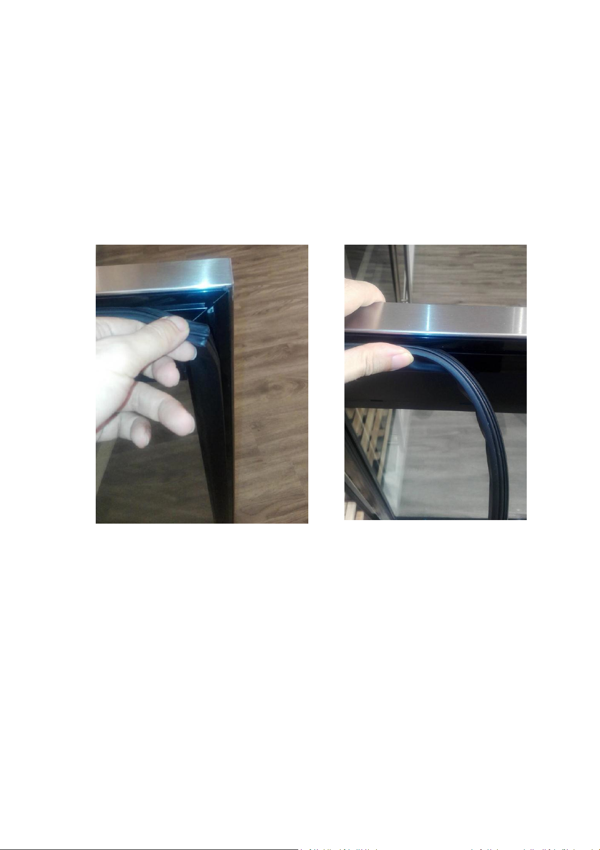
7.7Door gasket
The door seal is an accessory used for sealing between the glass door and the cabinet,follow
below instruction to replace the gasket:
1) Open the door.
2) Pull out the gasket begin from the corner,be careful not to damage the doorsealwithtoo
much force.
3) When installing, also start from the corner and press the gasket against the door lining.
24
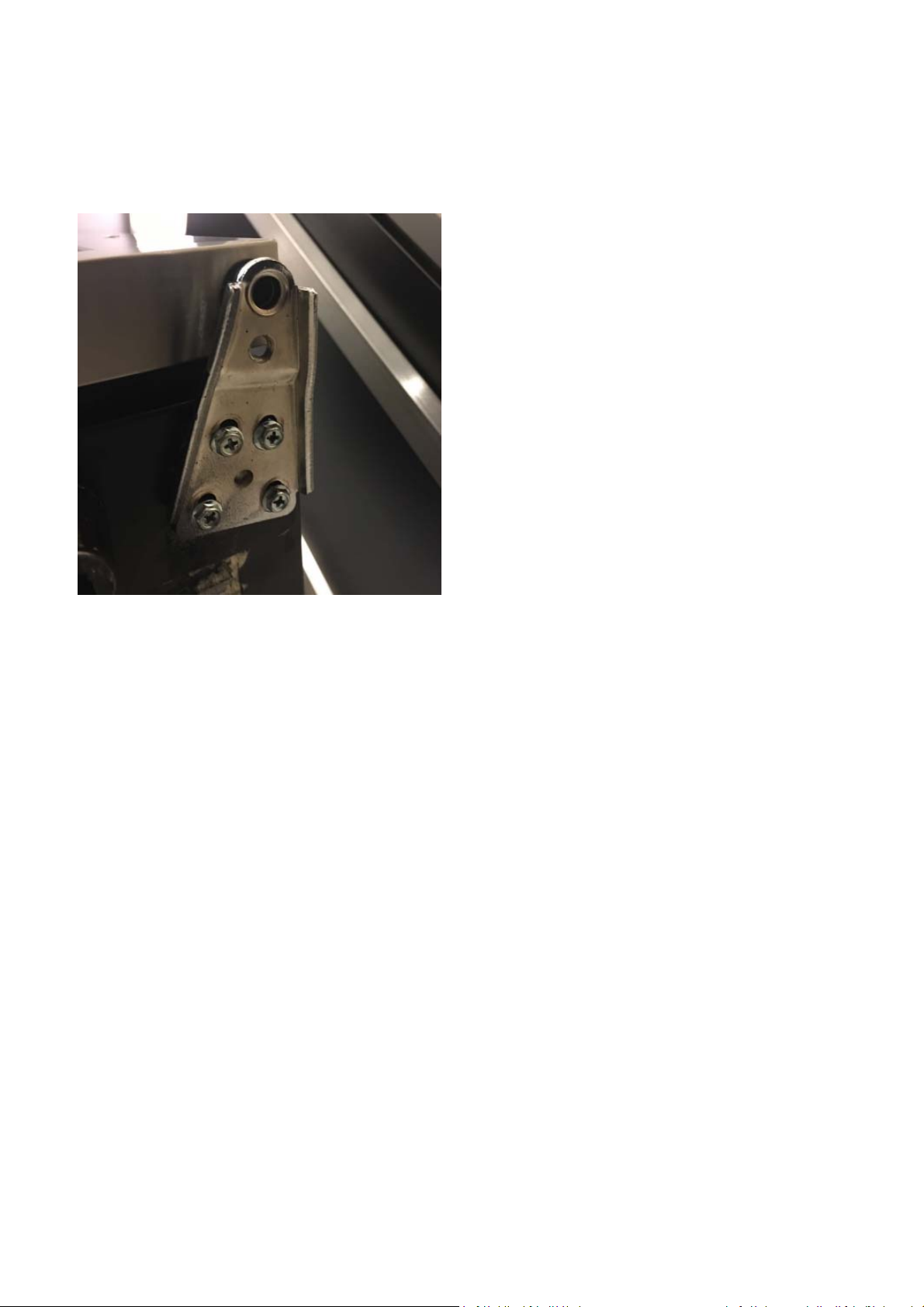
7.8.Door
Lay down the cabinet (glass door facing up)
Unscrew the lower door hinge screws and take off lower door hinge. Then you can take off the door
to replace the new one.
25
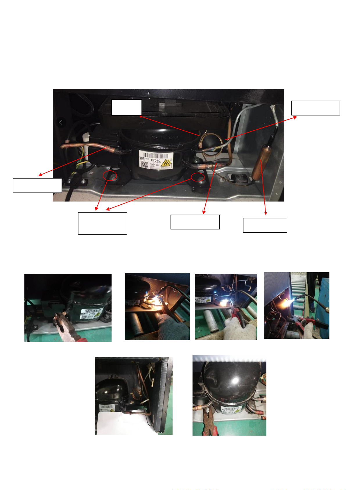
7.9.Compressor
A. Dismantling the compressor:
1) Cut the gas filling pipe and slowly leak out the refrigerant gas.(1)
2) Cut the dehydrator, condenser pipe and evaporator pipe by using a weldinggun(2)
3) Unscrew the bolts on compressor base and remove the compressor (3)
Gas filling pipe
Compressor
base screws
Capillary
Evaporator pipe
Condenser pipe
Dehydrator
12
3
25

7.10.Install a new compressor:
1)R e pl a ce the new compressor and connect the pipe of dehydrator,
condenser pipe and evaporator pipe (4)
2) Use a welding gun to weld the dehydrator, condenser pipe and evaporator pipe(5)
3)Afterwelding,evacuatedthecompressorandrefilltherefrigerantgas(6)
(Evacuate time≥15min,KPA≤15pa)
4) Sealing the gas filling pipe after refilling the gas(7)
5)Tidy up all pipe to avoid contacting with each other or touch the cabinet,in case there will have
noise during compressor working (8)
45
5
25

6
7
 Loading...