

Page 1
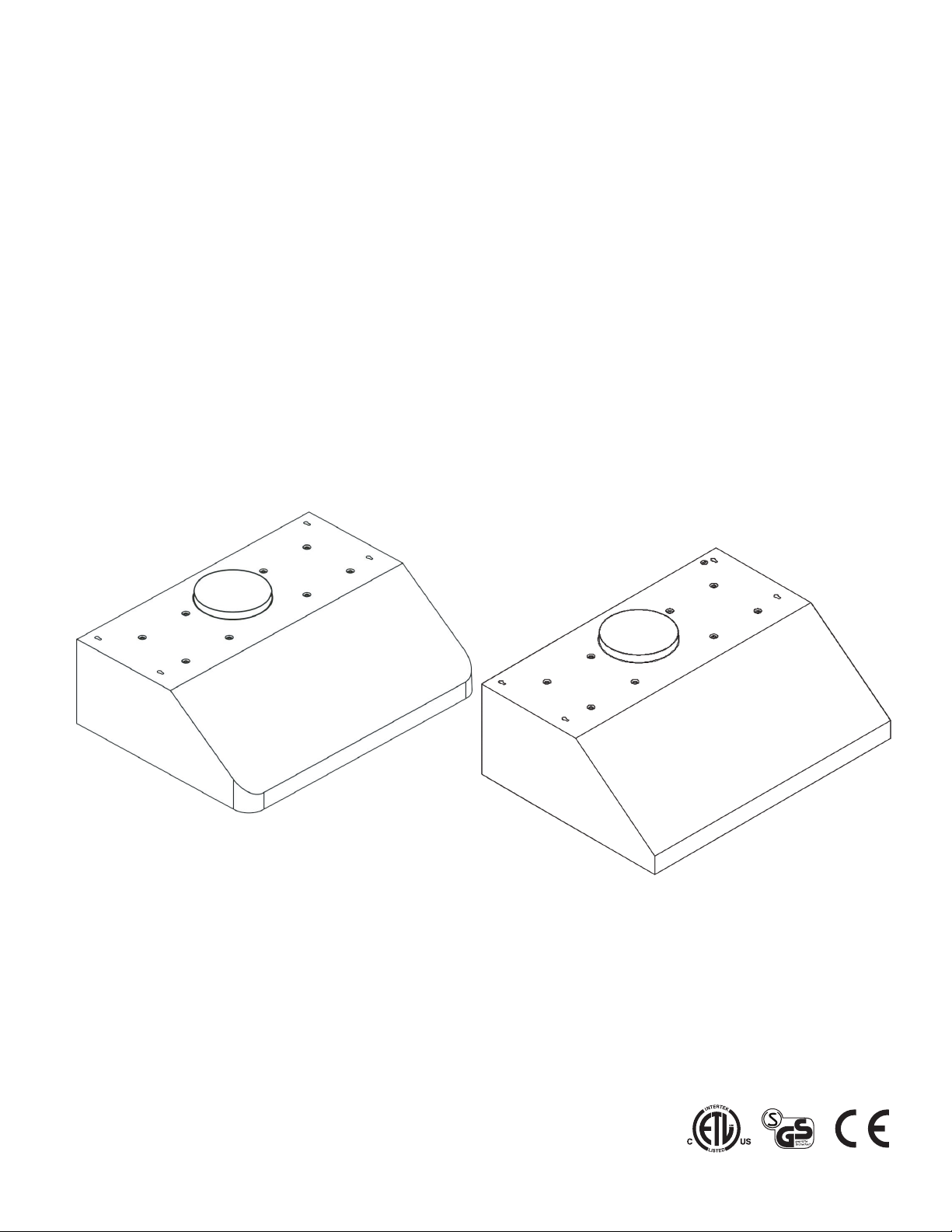
UNDERCABINET RANGE HOOD 30
Installation & User Manual
IMPORTANT NOTICE:
e these ins
Read and sa
Installer: Leave this guide with the homeowner
Homeowner: Keep this guide for future reference.
v
tructions.
.
23801-23805-2019d
Page 2
Important Safety Notice
READ ALL INSTRUCTIONS BEFORE INSTALLING AND OPERATING THIS APPLIANCE
Your safety and the safety of others is very important. We have provided many important safety
messages in this manual and on your appliance. Always read and obey all safety messages. All
safety messages will tell you what the potential hazard is, tell you how to reduce the chance of
injury, and tell you what can happen if the instructions are not followed.
This is the safety alert symbol. This symbol alerts you to potential hazards that can hurt you and
others. All safety messages will follow the safety alert symbol “ ” and the word “WARNING”.
Excessive Weight
Require three or more persons to
move and install this range hood.
Spinal or other bodily injuries
could occur if it is not followed.
Severe Injury
Rotating fan can cause severe
injury. Stay clear of fan when
power is present.
Hazard of electrical shock!
Do not perform service on an electrically live
system. Disconnect the main electrical supply
before servicing this device. Touching
electrical connectors or other exposed
electrical circuitry inside this range hood when
they are energized could result in death,
serious bodily injury, or property damage.
Hazard of Burns!
Light bulb become extremely hot when turned on. DO NOT touch bulb until
switched off and cooled. Touching hot bulbs could cause serious burns.
The manufacturer and/or distributor/reseller declines all responsibility in the event of failure to observe the
instructions given here for installation, maintenance and suitable use of the product. The manufacturer
and/or distributor/reseller further declines all responsibility for injury due to negligence and the warranty
of the unit automatically expires due to improper maintenance. The manufacturer and/or
distributor/reseller will not be held responsible for any damages to personal property or real estate or any
bodily injuries whether caused directly or indirectly by the range hood.
The installation in this manual is intended for qualified installers, service technicians or persons
•
with similar qualified background. Installation and electrical wiring must be done by qualified
professionals and in accordance with all applicable codes and standards, including fire-rated
construction.
DO NOT attempt to install this appliance yourself. Damage or Injury could result from installing
•
the unit due to lack of appropriate electrical and technical background.
Due to the size and weight of this range hood, at least two people are recommended for
•
installation to reduce the risk of fire, electric shock, or injury to persons.
Range hood may have very sharp edges; wear protective gloves if it is necessary to remove any
•
parts for installing, cleaning or servicing.
Ensure any nearby electrical service are OFF and stay OFF until the completion of installation to
•
reduce the risk of electrical shock, short-circuit, electrical spark which may cause injury or damage.
For general ventilating use only. DO NOT use to exhaust hazardous or explosive materials and
•
vapors.
In order to ensure the safe operation of fuel-burning heating equipment, it's air flow needs to be to
•
be considered for proper combustion. Follow the heating equipment manufacturer’s guideline
and safety standards such as those published by the National Fire Protection Association (NFPA),
and the American Society of Heating, Refrigeration and Air Conditioning Engineers (ASHRAE), and
the local code authorities.
To reduce the risk of fire and to disperse air properly, make sure to vent air outside. Sufficient
•
household air flow is required for the proper combustion of fuel-burning heating equipment, and
the exhaustion of their gases.
Pg 1
Page 3

Important Safety Notice
Ducted fans MUST always be vented to the outdoors.
•
DO NOT vent exhaust into spaces between walls, crawl spaces, ceiling, attics or garages.
•
•
•
•
•
•
•
•
•
•
TO REDUCE THE RISK OF A STOVE TOP GREASE FIRE:
•
•
•
•
•
•
•
•
old duct work should be cleaned or replaced if necessary to avoid the possibility of a grease
Any
Check all joints on duct work to insure proper connection and all joints should be properly taped.
Use only metal ductwork and this unit MUST be grounded.
Before servicing or cleaning unit, switch power OFF at service panel and lock service panel to
prevent power from being switched ON accidentally.
When cutting or drilling into wall or ceiling, be careful not to damage electrical wiring or other
hidden utilities.
All electrical wiring must be properly installed, insulated and grounded.
Use this unit only in the manner intended by the manufacturer. If you have questions, contact
the vendor.
DO NOT touch the bottom side of the range hood directly after usage because it may be hot.
Wait until it has cooled.
Make sure to inspect shipment and it's contents as soon shipment is received.
Plug in and test range hood and all its functions, (refer to Range Hood Operations, Page 13),
directly after receiving shipment, and before scheduling an installer.
Clean grease laden surfaces frequently.
Clean ventilating fan frequently.
Keep all surfaces clean from grease or oil build up.
Grease should not be allowed to accumulate on fan, baffle, spaces, filter, grease tunnel and oil
container.
Always turn range hood ON when cooking at high heat or when cooking flaming foods. Use high
settings on cooking range only when necessary.
Never leave burners or cooktop at high settings unattended. Boil overs cause smoking and
greasy spillovers that may ignite. Heat oils slowly on low or medium settings.
Always use appropriate cookware and utensils size.
Always use cookware appropriate for the size of the surface element.
fire.
TO REDUCE THE RISK OF INJURY TO PERSONS IN THE EVENT OF A STOVE TOP GREASE FIRE:
SMOTHER FLAMES with a close-fitting lid, cookie sheet, or metal tray, then turn OFF the burner.
•
BE CAREFUL TO PREVENT BURNS. NEVER PICK UP A FLAMING PAN—you may be burned.
KEEP FLAMMABLE OR COMBUSTIBLE MATERIAL AWAY FROM FLAMES. If the flames DO NOT
go out immediately, EVACUATE AND CALL THE FIRE DEPARTMENT or dial your local
emergency service immediately.
DO NOT USE WATER, including wet dishcloths or towels — a violent steam explosion may result.
•
Use an extinguisher ONLY if:
•
• You know you have a Class A, B, C extinguisher, and you already know how to operate it.
• The fire is small and contained in the area where it is started.
• The fire department is being called.
• You can fight the fire while maintaining a safe exit path.
TO REDUCE THE RISK OF INJURY TO PERSONS IN THE EVENT OF A GAS LEAKS:
Extinguish any open flame.
•
DO NOT turn on the range hood fan or any type of ventilator.
•
DO NOT turn on the lights or any type of appliance.
•
Open all doors and windows to disperse the gas. If you still smell gas, call the gas company and
•
fire department, or dial your local emergency service immediately.
Pg 2
Page 4

Table of Contents
INSTALLATION
Tools Needed
Parts Supplied
Venting Requirements
Height & Clearance
Duct Size Upgrade Calculator
Venting Methods
Electrical Requirements
Preparation
Installation
USE AND CARE
Range Hood Operations
...............................................................3
.............................................................4
..............................................5
...................................................6
........................................................7
..........................................8
..................................................................9
............................................................10-12
..................................13-14
Tools Needed
Marker
or Pencil
..............................6
Utility Knife
Troubleshooting
Use and Care Information
Specifications
Measurements and Diagrams
Electric Schematic
MAINTENANCE
Cleaning, Replacing Filter & Light Bulb
WARRANTY
Coverage & Exceptions
Disclaimer
Contact Information
....................................................................22
........................................................15
.....................................16
............................................................16
..............................17
...................................................18
.........................................21
................................................22
Measuring
Tape
...19-20
Level
Powered
Drill
Flat & Phillips
Screwdrivers
Pg 3
Page 5
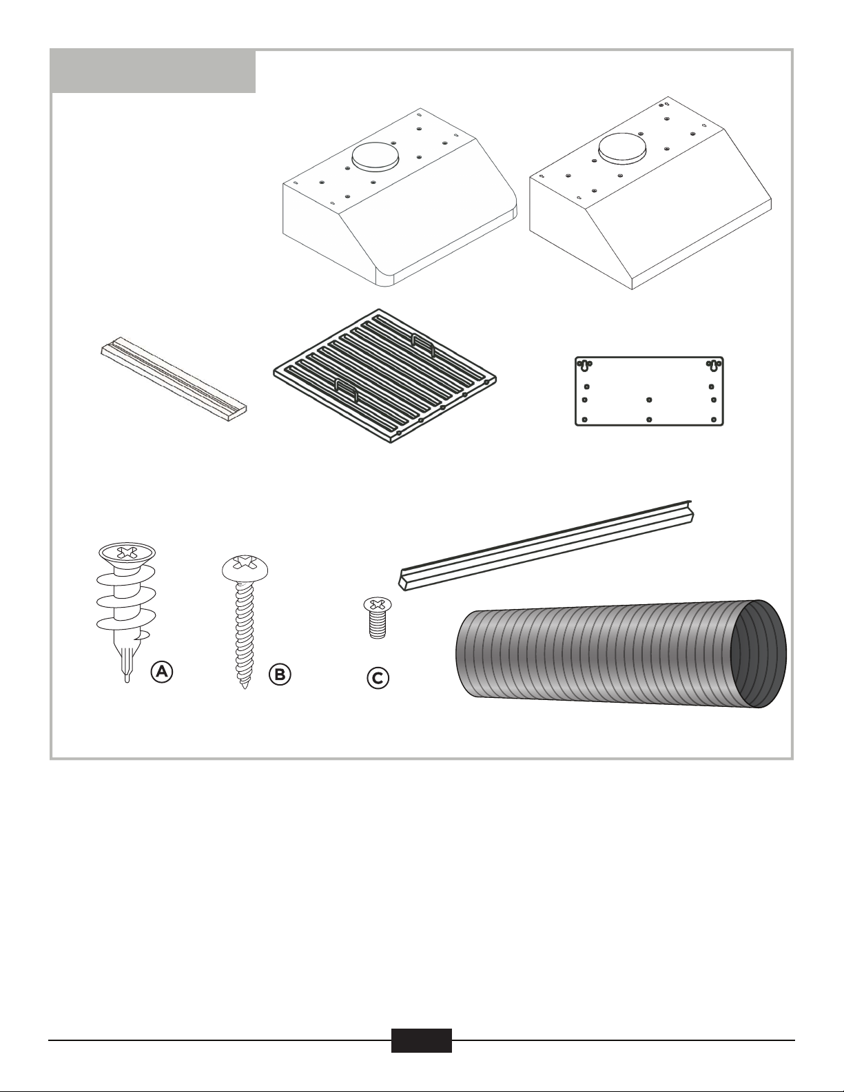
Parts Supplied
Range Hood
(Design will vary with model)
or
Baffle Filter Spacer
Qty: 6 PCS
(For dry wall or
sheet rock only)
Qty: 6 PCS
Stainless Steel Baffle Filter
Qty: 6 PCS
Range Hood Mounting Bracket
Grease Catch
Flexible Duct Tube
Pg 4
Page 6
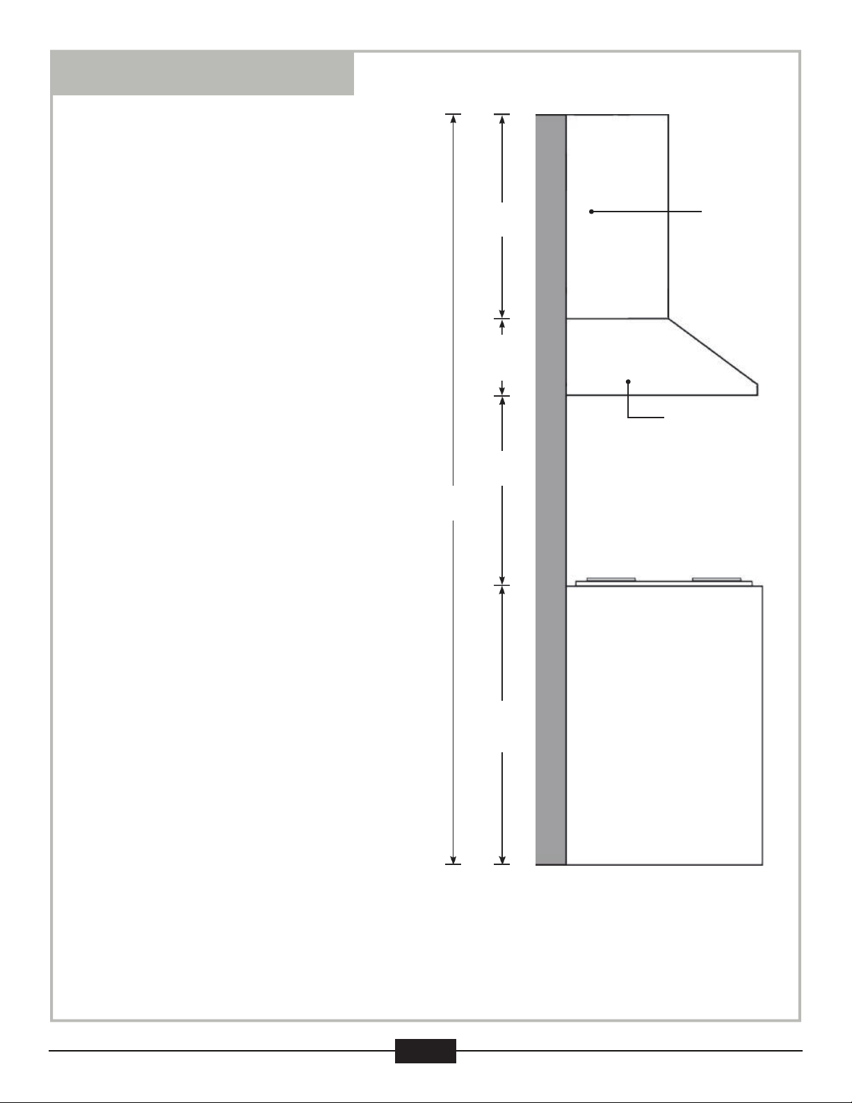
Venting Requirements
Vent system must terminate to the outside
•
(roof or side wall).
DO NOT terminate the vent system in an
•
attic or other enclosed area.
DO NOT use 4” (10.2 cm) laundry-type
•
wall caps.
Use metal/aluminum ducting only. Rigid
•
metal/aluminum ducting is recommended.
Always keep the duct clean to ensure
•
proper airflow.
Calculate the following figures before
•
installation.
Distance between the countertop/stove to
•
the range hood. (Recommended 27" to
~30").
Height
Range
Hood
Height
Cabinet
For the most efficient & quiet operation:
•
A distance of 27” to 30” is recommended
between stove top and the bottom of
range hood.
•
"27" is the lowest recommended for safe
operation; 30" is only recommended for
efficient operation, but can be mounted
higher."
•
It is recommended that the range hood be
vented vertically through the roof through
8” (20.3 cm) or larger round
metal/aluminum vent work.
•
The size of the vent should be uniform.
•
Use no more than three 90° elbows.
•
For best results, attempt to make a
minimum of 24" (61 cm) of straight vent
between the elbows if more than one
elbow is used.
•
DO NOT install two elbows together.
•
The length of vent system and number of
elbows should be kept to a minimum to
provide efficient performance.
•
The vent system must have a damper.
If roof or wall cap already has a damper,
DO NOT use the supplied damper
(if applicable).
Under Cabinet
Range Hood
Min:27’’
Max:30’’
Ceiling
Height
Countertop/Stove
36’’
Counter
To p
Use duct tape or equivalent to seal all joints in the vent system.
•
Use caulking to seal exterior wall or roof opening around the cap.
•
* Due to different ceiling height configurations, recommended height may not be applicable.
Pg 5
Page 7

Height & Clearance
IMPORTANT:
A minimum of an 8" round duct must be used to maintain maximum airflow efficiency.
•
A flexible 8" round duct is provided for convenience and for use in difficult installations,
•
however always attempt to use a smooth metal rigid type of ducting to maximize airflow
efficiency.
ALWAYS, when possible, reduce the number or transitions and turns. If long duct run is
•
required, increase duct size to. If a reducer is used, install a long reducer instead of a
pancake reducer. Any reductions of duct size will restrict and decrease airflow; to maximize
airflow flow efficiency place any reducers furthest away from any bends or transitions.
If turns or transitions are required, install them as evenly distanced as possible, and as far
•
away from the range hood as possible.
Please use the Duct Size Upgrade Calculator below to compute the total available duct run
•
when using elbows, transitions and caps.
It is important to install the hood at the proper mounting height. Hoods mounted too low is
•
considered unsafe and could result in heat damage and fire hazard; while hoods mounted too
high are harder to reach and will loose general effectiveness.
Minimum mount height between stove top to hood bottom should be no less than 28“.
•
Any less is considered unsafe and not recommended.
Maximum mount height between stove top to hood bottom can be higher than 31 inch*, but
•
is recommended to be the best efficiency.
If available, also refer to stove top manufacturer’s height clearance requirements and
•
recommended hood mounting height above range.
* Due to different ceiling height configurations, recommended height may not be applicable.
Minimum Duct Size:
Round - 8” minimum
•
Duct Size Upgrade Calculator
Minimum duct size recommended is 8” round. Maximum duct length recommend is 50 ft.
Any duct length over 50 ft is recommended to use a larger diameter duct size.
Survey the installation application and record the estimated length of ducting required or
used for that application. Record the number of bends, angle of bends, and/or any
transitional pieces used. Each bend or transition will reduce air flow and reduce the
recommended duct length.
Duct Deductions:
Each 90° bend 9 ft
Each 45° bend 5 ft
Each 8”
Side wall cap with damper 1 ft
Roof Cap (with factory Damper) 1 ft
7 ft
Duct Deduction Calculation Example:
(1) 90° bend, (1) 3¼” x 10” transition, (2) 45°
bends, (1) sidewall cap with damper (with
factory damper not installed)
-9ft + -7ft + -5ft + -5ft + -1ft = -27ft
Deduct 27 ft from 50 ft, giving you 23 ft of
available straight ducting before it is
recommended to upgrade your ducting size.
Pg 6
Page 8
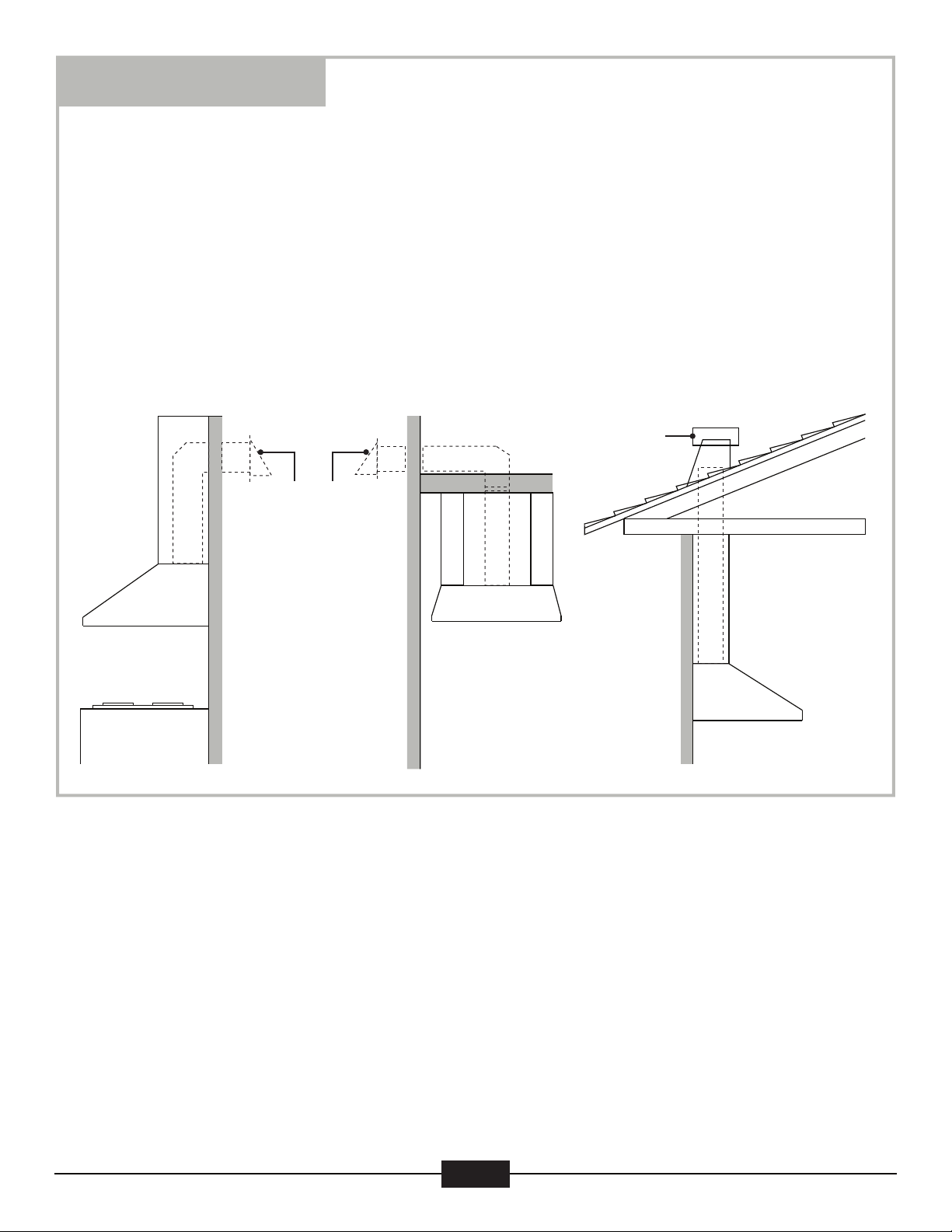
Venting Methods
This range hood is factory set for venting through the roof or wall.
•
Vent work can terminate either through the roof or wall. To vent through a wall, a 90° elbow
•
is needed.
IMPORTANT:
NEVER exhaust air or terminate duct work into spaces between walls, crawl spaces, ceiling,
•
attics or garages. All exhaust must be ducted to the outside.
Use metal/aluminum duct work only.
•
Fasten all connections with sheet metal screws and tape all joints with certified duct tape or
•
equivalent.
Use caulking to seal exterior wall or roof opening around the cap.
•
Vertical Roof VentingHorizontal Wall Venting
Option 1:
Side Wall Cap
Option 2:
Roof Cap
Pg 7
Page 9

Electrical Requirements
IMPORTANT: Observe all governing ordinances and local codes.
(Please consult with a qualified electrician for any electrical wiring)
It is the customer’s responsibility:
•
To contact a qualified electrical installer.
•
To assure that the electrical installation is adequate and in conformance with National
Electrical Code, ANSI/NFPA 70 — latest edition*, or CSA Standards C22. 1-94, Canadian
Electrical Code, Part 1 and C22. 2 No. 0-M91 - latest edition** and all local codes and
ordinances.
•
Provide a circuit protected power service; preferably a Ground Fault Circuit Interrupter
("G.F.C.I."): 120-volt, 60 Hz, AC, with at least 5-amps of available service.
•
Enlist a qualified electrician to ensure the range hood and electrical lines are adequately
grounded and properly protected. NEVER electrically ground to a gas pipe.
IMPORTANT: Save this Installation Guide for future reference and/or electrical inspector use.
The range hood should be connected with a circuit breaker protected power service.
Wire sizes (copper wire only) and connections must conform with the rating of the appliance
as specified on the model/serial rating label. Wire sizes must conform to the requirements of
the National Electrical Code ANSI/NFPA 70 — latest edition*, or CSA Standards C22. 1-94,
Canadian Electrical Code Part 1 and C22. 2 No. 0-M91 - latest edition** and all local codes and
ordinances. A U.L. - or C.S.A. - listed conduit connector must be provided at each end of the
power supply cable (at the range hood and at the junction box).
Copies of the standards listed may be obtained from:
* National Fire Protection Association
Batterymarch Park
Quincy, Massachusetts 02269
**
CSA International
8501 East Pleasant Valley Road
Cleveland, Ohio 44131-5575
Pg 8
Page 10

Preparation
Advanced Preparations:
1.
Familiarize yourself with the controls of the range hood by
reading through Range Hood Operations, Page 13.
2.
Place the range hood on a flat, stable surface. Connect the
range hood to a designated standard outlet (please refer the
product label for the suitable voltage of this unit) and turn
on the range hood. Verify all operations of the range hood
by referring to Range Hood Operations, Page 13.
3.
Place all supplied parts and required hardware on a flat, stable surface and verify the
presence of all supplied parts listed on Page 4.
4.
Carefully remove the white plastic protective coat from the chimney covers and range hood.
Preparations:
NOTE: To avoid damage to your hood, prevent debris from entering the vent opening.
Determine and mark the center line on the ceiling where the range hood will be installed.
1.
Make sure there is proper clearance within the ceiling or wall for exhaust vent.
A straight, short vent run will allow the hood to perform more efficiently.
2.
Try to avoid as many transitions, elbows, and long run as possible. This may reduce the
3.
performance of the hood.
IMPORTANT: Before fastening any surfaces together, remove any protective cover from that
4.
surface; remove the remainder of the protective coating after installation completion.
Use silver tape or duct tape to seal joints between pipe sections.
5.
For installing under the cabinet with recessed bottom, attach 4-inch wide wood filler strips
6.
(not provided) on each side. Refer to Figure 1.
7.
Using references in Measurements and Diagrams on Page 17, create access opening for
electrical wires and hood exhaust under the cabinet.
CAUTION: If moving the cooking range is necessary to install the hood, turn OFF the
power on an electric range at the main electrical box. SHUT OFF THE GAS BEFORE
MOVING A GAS RANGE.
8.
Puncture the knockout holes (for mounting under the cabinet) on the hood as shown in
Figure 2.
9.
If necessary, attach two rubber stands with 3M adhesive tapes to the back corners of the
hood.
Severe Injury
Rotating fan can cause severe
injury. Stay clear of fan when
power is present.
Figure 1
Figure 2
Pg 9
Page 11

Installation
Installations (refer to Page 4 for Parts Supplied):
1.
Measure the distance between the stove top and the bottom of range hood. A *distance of
27” to 30” is recommended. *Due to different ceiling height configurations, recommended
height may not be applicable.
2.
Mount the Range Hood:
There are two ways recommended to mount this range hood;
(A)
Mounting this range hood onto the underside of an existing cabinet or structure (without
the Range Hood Mounting Bracket):
1) Using references from the 'Height & Clearance' Page 6 and 'Measurements & Diagrams'
Page 17 sections, center the range hood body beneath your installation space; align the topfront edge of the range hood with your cabinet face or installation structure (or however
you would prefer to have the range hood aligned); mark the location of the air duct
passage.
2) Manually double check the measurements of the range hood dimensions and your
installation marks to ensure the range hood is installed exactly where you prefer. Cut a hole
allowing for clearance of the air duct structure.
3) Reposition the range hood at its installation space as flat as possible against the
mounting surface; check measurements again and ensure it is aligned to your installation
preference; mark the location of the power cord (this can be repositioned). Drill a hole to
allow clearance for the power cord through your installation structure.
4) Reposition the range hood at its installation space flat against the mounting surface;
ensure the power cord is fed through its installation hole; check measurements again and
ensure it is aligned to your installation preference; mark the screw hole mounting positions
at the top surface of the range hood body; mark the entire shape of the mounting holes or
keyholes. For the most accurate installation center punch and pilot drill the holes for the
mounting screws.
5) Using the keyhole mounting holes, screw 2 mounting screws at those locations, allowing
1/4-inch of headspace to allow the range hood to temporarily hang from those screw heads,
using the keyhole mounting features.
6) Add additional screws to at least 2 more mounting locations, as widespread as possible,
and then fasten all mounting screws while ensuring the range hood stays aligned with your
installation preference.
CAUTION: Make certain the range hood is secure before releasing! Finish tightening all screws
until secure. Be cautious when using an electrical screwdriver as damage to the range hood
may occur. Adding additional mounting screws through the bare sheet metal of the range
hood is not necessary for this installation option, but is possible; avoid drilling into wires,
components and critical fixtures.
Figure 3 Figure 4 Figure 5
Pg 10
Page 12

Installation (Continued)
Mounting this range hood onto a vertical wall using the Range Hood Mounting Bracket:
(B)
1) Attach the Range Hood Mounting Bracket onto the range hood body. (Recommended to
use an anti-vibration thread glue) Fasten screws securely. Figure 3.
2) Using references from the 'Height & Clearance' Page 6 and the 'Measurements &
Diagrams' Page 17 sections, temporarily mark the installation surface (wall) estimating the
position of the range hood along the bottom surface of the range hood to ensure its proper
clearance from the stove top, and also proper leveling.
3) Position the range hood body (with Range Hood Mounting Bracket) at its designated
mounting location using the marks made in the previous step, and then mark the entire
shape of each mounting hole.
4) Partially screw 2 mounting screws into the wall, in the position of the keyhole mounting
holes; allowing approximately 3/16-inch headspace to hang the Range Hood Mounting
Bracket onto the mounting screws. Hang the Range Hood Mounting Bracket onto the headspaced screws using the keyhole mounting holes. Check position and leveling of the range
hood, and then tighten the mounting screws completely. Figure 5.
5) Check the leveling of the range hood, and then fasten additional mounting screws
through the various mounting holes along the lower (inside) rear panel of the range hood,
through the bare sheet metal. Use structural studs or solid braces to screw into where
possible. Avoid drilling into any wires, cables, components and critical fixtures.
CAUTION: Make certain the range hood is secure before releasing! Finish tightening all screws
until secure. Be cautious when using an electrical screwdriver as damage to the range hood
may occur. Adding additional mounting screws through the bare sheet metal of the range
hood is suggested for this installation option; avoid drilling into wires, components and critical
fixtures. The power cord can be repositioned reusing the existing hardware. Figure 4.
Additional Points:
• For the stabilization of the range hood and safety of the users, it is recommended to use
pre-drilled mounting holes provided along the lower rear surface of the range hood. Use at
least 2 of these lower mounting holes, as widespread as possible, into a structural stud or
supportive brace within the wall.
• Use 8-inch round metal duct (adhere to your local building codes) to connect the exhaust
duct of the range hood to the ductwork of your household. Use certified duct tape
equivalent or hardware to secure all duct joints and make air tight. Figure 6.
• SAFETY WARNING: Due to risk of electrical shock, this range hood must be properly
grounded. Ensure the electrical service supplied to this unit is installed or inspected by a
qualified electrician and in accordance with local and national electrical codes and
regulations. Before attempting to install this unit, connecting any power connections, or do
any servicing on this unit, turn off the main electrical switch (circuit breaker) at the service
panel, and consider locking the service panel so that it cannot be accidentally switched on.
• Confirm there is no live power service; plug the range hood into your power socket. If you
are using a hardwired power cable configuration, hardwire the power cord inside an
electrical junction box, certified for use within your local codes.
• Ensure excess wiring is managed with a wire tie and will not be damaged during normal
usage.
• Install the Grease Catch by placing it into the inner, lower, rear ledge of the range hood
assembly. Ensure the orientation is as shown in the diagram: Figure 7. With opening of the
grease trap facing upward, and the extended lip towards the rear.
Pg 11
Page 13

3.
Installation (Continued)
3.
Install the baffle filters into the range hood. Figure 8.
a)
Angle the baffle filter so that the rear edge of the baffle filter enters the range hood
cavity, and touches the back wall of the range hood.
Then lift the front edge of the baffle filter so that it aligns with a groove in the lower
b)
front panel of the range hood assembly.
c)
Then slide the baffle filter towards the front of the range hood body, into the groove of
the lower front panel of the range hood assembly.
Keeping pressure on the baffle filter to hold it towards the front of the range hood
d)
body, while in the groove of the lower front panel of the range hood assembly, lower the
rear edge of the baffle filter onto the grease catch, previously installed in Step 6.
e)
Ensure the baffle filter partially rest inside the opening of the grease catch, against the
extended lip of the grease catch.
Slide the baffle filter to one side and repeat for remaining baffle filter(s).
f)
4.
If your model size has baffle filter spacers: they are easier to install before the baffle filters;
and are more easily installed at the sides of the range hood; use the same steps as instructed
in Step 7.
Double Check all power connections, ducting connections, fastened screws, remove any
5.
loose debris or tools, and then apply power from your main switch board. Test Ground Fault
Circuit Interrupter (G.F.C.I. or G.F.I.)
6.
Test operations (see Range Hood Operations Page 13). Leave this manual for the range
hood owner.
Figure 6
Figure 7
Figure 8
Pg 12
Page 14

Range Hood Operations
Control Panel, Display and Functions:
In addition to the remote control feature, this range hood is also equipped with a heat
sensor that will self-calibrate in 5 seconds when the range hood is first electrically
activated and beeps when self-calibration is done. To con- serve energy, the LCD panel
will turn off automatically after 5 seconds of inactivity. For the best results, start the
range hood before cooking and allow it to operate several minutes after the cooking is
completed to clear all smoke and odors from the kitchen.
Activating Ventilation Function:
While the range hood is off, use the Increase or Decrease buttons to start the blower.
•
Press Increase button to increase blower speed (“F1” to “F4”) as indicated in LCD panel.
The Increase button cycles blower settings from “off” (00), “quiet” speed (F1), “low”
speed (F2), “medium” speed (F3) to “high” speed (F4).
While the range hood is on and the blower is running, press Decrease button to decrease
•
blower speed (“F4” to “F1”) as indicated in LCD panel. The Decrease button cycle blower
settings from “high” speed (F4), to “medium” speed (F3), “low” speed (F2), “quiet” speed
(F1) to “off” (00).
Adjusting Heat Sensitive Auto Speed (HSAS) Function:
Press the Auto Function button to turn On/Off the Auto Mode. The Auto Function Icon
•
will illuminate in the LCD Panel when Auto Mode is On.
While the range hood is off, press and hold Auto Function button to enter the
•
temperature setting mode. Use the Increase or Decrease button to adjust the comparison
temperature value between the internal and external heat sensors from “8°” to
“20°” (these values are not exact measurements but are level settings). The temperature
setting mode will exit automatically after 5 seconds of inactivity.
While the range hood is off and Auto Function is activated, the blower will turn on to its
•
highest speed automatically when the internal temperature is 4 times above the external
temperature. It will then adjust the speed level (between F4 to F1) automatically
according to the detected temperature between the sensors (4 times to 1 time). The
automatic speed level can be manually overwritten by pressing the Increase or Decrease
button and then Auto Function will reactivate after 2 minutes. The blower can ONLY be
turned off MANUALLY or by activating the Power-Off Delay Timer Function.
Pg 13
Page 15

Range Hood Operations
Control Panel, Display and Functions:
Activating Light Function:
Press Light button once to turn on the lights, and once again to turn off the lights.
•
CAUTION:
DO NOT touch the lights or surrounding surface until turned OFF and allowed to cool.
Activating Power-Off Delay Function:
While the range hood is on and the blower is running, press Power-Off Delay button to
•
activate delay off timer and “Timer Shutoff” icon will appear in LCD panel. Adjust to
desired period of delay off timer by pressing Increase or Decrease button (minimum 1
minute to maximum 15 minutes). Timer begins to countdown immediately, when it
reaches 0, the blower will shut off.
Adjusting Clock Function:
While the range hood is off, press Power-off Delay button once to enter the clock setting
•
mode; use the Increase or Decrease button to set the Hours column; press the Power-off
Delay button again to set the Minutes column; press the Power-off Delay button again to
exit the clock setting mode.
Remote Control Sensor:
Remote control sensor receives infrared (“IR”) signal from the remote control. The
•
maximum distance for IR data transmission is about 3 meter (10 ft.) and requires direct
line of sight. The transmission distance may vary depending on temperature and remote
control battery condition.
Note: Light settings are independent from other settings (including power-off delay)
and are required to be manually turned on or off.
Pg 14
Page 16

Troubleshooting
If the range hood or light
does not operate after
installation:
The range hood vibrates
when the suction is on:
The suction or fan seems
weak:
Check if the range hood has been plugged in, make
•
sure that all power has been turned back ON, and all
electrical wiring are properly connected.
Swap out light bulb to working ones to determine
whether it is caused by defective bulbs. See
•
Replacing the light bulbs on Page 20.
•
The range hood might not have been secured
properly on to the ceiling or wall. Check with your
installer
•
Check that the duct sized used is at least 8” round.
Range hood WILL NOT function efficiently with
insufficient duct size.
•
Check if duct is clogged or if damper unit
(half-circular flapper) is not installed correctly or
opening properly. A tight mesh on a side wall cap
unit might also cause restriction to the air flow.
The lights work but the
suction is not spinning, is
stuck or is rattling.
The hood is not venting out
properly:
The blower might be jammed or scraping the
•
bottom due to shipping damage. Please contact us
immediately.
Make sure the distance between the stove top and
•
the bottom of the hood is within 28” and 31” in
distance. *Due to different ceiling height
configurations, recommended height may not be
applicable.
Reduce the number of elbows and length of duct
•
work. Check if all joints are properly connected,
sealed, and taped.
Make sure the power is on high speed for heavy
•
cooking.
Note: For all other inquiries, please contact us. Our contact information can be found on the back cover page.
Pg 15
Page 17

Use and Care Information
Operations:
Read and understand all instructions and warnings in this manual before operating the
•
appliance. Save these instructions for future reference.
Always leave safety grills and filters in place. Without these components, operating blowers
•
could catch on to hair, fingers and loose clothing.
NEVER dispose cigarette ashes, ignitable substances, or any foreign objects into blowers
•
NEVER leave cooking unattended. When frying, oil in the pan can easily overheat and catch
•
fire. The risk of self combustion is higher when the oil has been used several times.
NEVER cook using “open” flames under the range hood. Check deep-fryers during use:
•
Superheated oil may be flammable.
Cleaning:
The saturation of greasy residue in the blower and filters may cause increased inflammability.
•
Keep unit clean and free of grease and residue build-up at all times to prevent possible fires.
Filters must be cleaned periodically and free from accumulation of cooking residue (see
•
cleaning instructions on Page 19). Old and worn filters must be replaced immediately.
DO NOT operate blowers when filters are removed. Never disassemble parts to clean
•
without proper instructions. Disassembly is recommended to be performed by qualified
personnel only. Read and understand all instructions and warnings in this manual before
proceeding.
Specifications
Body Material Stainless Steel; Seamless Welds; Brushed Satin Finish
Overall Voltage
Maximum Power Usage
Lighting Wattage
Lamp Type
Motor Power
Motor Speed
Motor Type
Fan Type
Ducting / Venting
Control Type
Protections
Filtration Type
, 60Hz
115V
246W
3W
(x2)
SV12-LED
120W (x2)
4 Levels
Dual, Ultra Quiet
Centrifugal
8 inches, Round, Top Venting
Touch-Sensitive, Electronic Control Panel w/ Heat Sensor & Remote Controller
Electrical Short Fuse, Radio Frequency Interference
Stainless Steel Baffle with Grease Catch
1. In House Test Static Pressure "0".
2. One sone is roughly equivalent to the sound of a refrigerator (1kHz) at 40 decibels.
3. Subject to change without notice, please contact your local reseller for details.
Pg 16
Page 18

Measurements and Diagrams
1. All measurements in parenthesis are in millimeters.
2.All inch measurements are converted from millimeters, therefore inch
measurements are estimated.
Overall (PS13): Overall (PS37):
29-1/2’’ (750)
Rear Knocknut Holes: Hood-mounting Bracket:
29-1/2’’ (750)
Pg 17
Page 19

Electric Schematic
Lamp (-)
AC_L
AC_N
MO_N
MO_1
MO_2
MO_3
MO_4
Lamp (+)
Black
White
White
White
Blue
Pink
Red
Orange
Black
Live
Neutral
Fan (-)
Fan 1
Fan 2
Fan 3
Fan 4
MOTOR
Green
12uf/250v (110v)
Yellow
Yellow
4uf/500v (220v)
* Subject to change without notice, please contact your local reseller for details.
Pg 18
Page 20

Maintenance
SAFETY WARNING: Never put your hand into area housing the fan while the fan is operating!
For optimal operation, clean range hood and all baffle/spacer/filter/grease tunnel/oil container
regularly. Regular care will help preserve the appearance of the range hood.
Cleaning Exterior Surfaces:
Clean periodically with hot soapy water and clean cotton cloth. DO NOT use corrosive or
•
abrasive detergent (e.g. Comet Power Scruv®, EZ-Off® oven cleaner), or steel wool/scoring
pads, which will scratch and damage the stainless steel surface. For heavier soil use liquid
degrease such as “Forumla 409®” or “Fantastic®” brand cleaner.
If the finish looks splotchy (stainless steel hood), use a stainless steel cleaner to clean the
•
surface of the hood. Use a dry soft towel to dry the hood. CAUTION: Do not leave the
cleaning solution on the surface too long as this may damage the finish. Avoid getting
cleaning solutions into or onto the control panel, computer components, wires or wired plugs.
Always wipe/clean/polish in the same direction as the brushed stainless steel finish. Never
•
wipe against the grain.
After cleaning, you may use non abrasive stainless steel polish such as 3M® or ZEP®, to
•
polish and buff out the stainless luster and grain. Always scrub lightly, with clean cotton
cloth, and with the grain.
DO NOT allow deposits to accumulate or remain on the hood, as they will become harder to
•
clean, and may cause scratching of the finish.
DO NOT use ordinary steel wool or steel brushes. Small bits of steel may adhere to the
•
surface and cause rusting.
DO NOT allow salt solutions, disinfectants, bleaches, or cleaning compounds to remain in
•
contact with stainless steel for extended periods. Many compounds contain chemicals, which
may be damaging. Rinse with water after exposure and wipe dry with a clean cloth.
Cleaning Aluminum Grease Filter / Stainless Steel Filterless Grill:
IMPORTANT: Drain oil from oil containers before potential residue overflow!
The metal filters are intended to help filter grease, residue and moisture from cooking.
•
They are required to be kept clean for performance and safety concerns, and may require
replacement if neglected.
Filters should be cleaned after every 30 hours of use or sooner depending on usage
•
conditions.
Remove and clean by hand or dishwasher. NOTE: Some newer dish detergents may cause
•
marking or blackening of aluminum metals, such as the mesh aluminum filters. Spray
“Formula 409®” or equivalent degreasing detergent and allow to soak if heavily soiled. Rinse
with warm water, allow the filters to dry and then and re-install before using hood.
Replacing Filters:
Should filters wear out due to age and prolonged use, please contact your local reseller for
•
replacement filters. Consider preemptively purchasing an extra set of filters to store on hand,
or upgrading to stainless steel baffle filters.
Note: Also replace damaged filter that has punctured or broken mesh, bent or broken frame.
•
Pg 19
Page 21

Maintenance (Continued)
Hazard of Burns!
Light bulb become extremely hot when turned on. DO NOT touch bulb until
switched off and cooled. Touching hot bulbs could cause serious burns.
Replacing The Light Bulb:
Check the range hood tag for lamp specifications. Halogen bulbs will not work on "LED"
•
models (they will lightly pulse or flash).
Before performing any task outside of basic operation, turn off the power supply and/or
•
unplug the unit.
Before attempting to handle the light bulbs, ensure the bulbs are cool to the touch,
•
including any adjacent working surfaces
Replacing LED Light Fixture:
•This range hood uses LED light fixture: 3W Max 12V LED
•Make sure the range hood is unplugged or turn OFF breaker and the lights are cool to
touch.
•Place a flat-head screwdriver between light housing and hood body, gently pry up the light
housing and search for the metal clip. (Recommended: use multiple layers of tape over the
screwdriver head to prevent any scratching of the finish)
•Apply force to the metal clip and pull out the light fixture. Disconnect the power cable and
discard the old light fixture.
•Reverse the steps to install a new halogen light fixture. Turn ON breaker and range hood
to test for operation.
Pg 20
Page 22

Warranty
One Year Parts Warranty:
For one year from the date of original purchase, your local reseller will provide free of
charge, non-consumable replacement parts or components that failed due to manufacturing
defects. Subject to the conditions and limitations set forth below, your local reseller will, at
its option, either repair or replace any part of its products that prove defective by reason of
improper workmanship or materials. Repaired parts or replacement products will be
provided by your local reseller on an exchange basis, and will be either new or refurbished to
be functionally equivalent to new. The consumer is responsible for all shipping costs.
Consumable parts not covered by this warranty include but not limited to: Light bulbs, metal,
aluminum and charcoal filters.
Who is Covered:
This warranty is extended to the original purchaser for products purchased for ordinary
home use.
This Warranty Will Be Voided When:
Product damaged through negligence, improper installation, accident, abuse, misuse, natural
disaster, insufficient or excessive electrical supply, abnormal mechanical or environmental
conditions, or any unauthorized disassembly, repair, modification, or failure to follow
installation instructions. When product is used commercially or other than its intended
purpose. Damaged because of improper connection with equipment of other manufacturers.
Repaired or modified by anyone other than your local reseller’s authorized agents. This
limited warranty also does not apply to any product on which the original identification
information has been altered, obliterated or removed, has not been handled or packaged
correctly or has been sold as second-hand.
What is Not Covered:
Consumable parts such as light bulbs, metal and charcoal filters. The natural wear of finish,
and wear due to improper maintenance, use of corrosive and abrasive cleaning products,
pads, and oven cleaner products. Chips, dents or cracks due to abuse, misuse, freight
damage, or improper installation. Damage of product caused by accident, fire, floods or act
of God. The manufacturer and/or distributor/reseller is not liable for, and does not cover
under warranty, any loss of properties or any costs associated with removing, servicing,
installing, or determining the source of problems with this product.
This warranty is valid in the country of the original purchase at retail. It is non-transferable and
applies only to the original purchaser and does not extend to subsequent owners of this
product. Any applicable implied warranties, including the warranty of merchantability, are
limited in duration to a period of express warranty as provided herein beginning with the date
of original purchase at retail and, no warranties, whether express or implied, shall apply to this
product thereafter.
To obtain warranty service, you may contact your local reseller from which you purchased this
product. Please confirm the terms of your local reseller’s policies prior to contacting.
Typically, you must include product identification information, including model number and
serial number with a detailed description of the problem you are experiencing. You must also
include proof of the date of original retail purchase as evidence that the product is within the
applicable warranty period.
The information in this document is subject to change without notice, please contact your local reseller for updated details.
Pg 21
Page 23

Disclaimer
Carefully inspect all items for damages before accepting delivery. Note and picture any
damages to the external box, contents or item to the carrier and written on the freight bill or
delivery receipt. Request name and signature of the carrier’s agent and keep copy to support
your claim. Upon acceptance of items, owner assumes responsibility for its safe arrival. Report
damages to the carrier and file a claim immediately. Failure to do so may result in the denial of
your claim. The carrier will furnish you with necessary forms for filing
a claim.
Damages caused during transit are not covered under our warranty. Please contact us for
additional help in filing your insurance claim.
Please inspect contents of package(s) carefully upon receiving! We must be notified of any
damages and/or missing parts within five (5) days upon your receipt of package(s). Claims will
not be accepted after five (5) days. NOTE: Items were thoroughly tested and carefully packed
in our factory before shipping.
Products must be returned in good working condition with ALL original parts and
documentation packed in ALL original cartons, fillers and shipping cartons. A restocking fee of
15% will be charged for all approved return(s). Exchanges or returns may not be accepted if
any packaging is missing.
Be sure to inspect the hood for damage and defects, and also function test the hood before
installation. Appearance flaws of the hood found after installation and not affecting hood
performance is not covered under our warranty for returns or exchanges. Service visits not
covered under warranty.
Before Installation: Return for exchange or refund (please see above for acceptable returns).
After Installation: NO exchange or refund.
Contact Us
If you need any assistance, please contact your local reseller. Please have your order number
and model of the range hood ready. This information will help process your request or inquiry
more effectively.
If you need replacement parts, we recommend that you only use genuine parts. Our
accessories and parts are engineered and designed specifically for this series of range hood,
each is rigorously tested assuring the utmost in durability and reliability, providing a factory
match, factory-installed appearance and functionality tailored to each individual range hood
model.
The information in this document is subject to change without notice, please contact your local reseller for updated details.
Pg 22
Page 24

21700 Barton Road, Colton, California 92324 USA
Phone Number: (800) 827-5950
CavaliereHoods.com
 Loading...