

Page 1

User Manual
Radio Remote Control
LR
C
-L1 Transmi
tter Unit
Page 2

User Manual LRC-L1
2 Subject to change without notice. Version 1.0.0 - 11/2010
Cattron-Theimeg Europe GmbH & Co. KG
41066 Mönchengladbach
Krefelder Straße 423 - 425
Germany
Phone: +49 (0) 2161 / 6363 - 0
Fax: +49 (0) 2161 / 6363 - 100
Internet: www.cattron-theimeg.de
E-Mail: info@theimeg.de
Copyright:
This technical document or parts thereof may not be reprinted or copied – except for own use for the
operation of the radio transmitter system – without the written permission of Cattron-Theimeg Europe GmbH
& Co. KG. It may not be made accessible to a third party. The copying of the described radio remote control
system is not permitted.
Page 3

User Manual LRC-L1
Version 1.0.0 - 11/2010 Subject to change without notice. 3
Table of Contents Page
1 Introduction .................................................................................................................................. 4
2 Safety Instructions ....................................................................................................................... 5
2.1 Used Symbols and Definitions for Warnings................................................................................................5
2.2 General Information on Safety .....................................................................................................................5
2.3 Use for Intended Purpose ............................................................................................................................6
2.4 Improper Use................................................................................................................................................6
2.5 Safety Instructions for Assembly/Disassembly ............................................................................................6
2.6 Operation of Radio Transmitter System Components with Identical System Address ................................ 6
3 General .......................................................................................................................................... 7
3.1 Radio Transmission......................................................................................................................................7
3.1.1 Continuous Transmission..........................................................................................................................7
3.1.2 Area of operation.......................................................................................................................................7
3.1.3 Radio Interference .....................................................................................................................................7
3.2 System Address ...........................................................................................................................................7
3.3 System Parameters ......................................................................................................................................7
4 Transmitter Unit............................................................................................................................ 8
4.1 General.........................................................................................................................................................8
4.2 Display Option ..............................................................................................................................................8
4.3 Before turning on ..........................................................................................................................................9
4.4 Turning the transmitter on (Standard) ..........................................................................................................9
4.5 Turning the transmitter on with STOP switch check (only when requested by customer)...........................9
4.6 Turning the transmitter off ............................................................................................................................9
4.7 STOP Command ..........................................................................................................................................9
4.8 Automatic Turn-off ......................................................................................................................................10
4.9 Status LED .................................................................................................................................................10
5 Battery & Battery Charger ......................................................................................................... 11
5.1 Connecting the Battery Charger.................................................................................................................11
5.2 Charger Status Indication...........................................................................................................................11
5.3 Charging the Battery...................................................................................................................................12
5.4 Defective Battery ........................................................................................................................................12
5.5 Battery Discharging ....................................................................................................................................12
6 RF Channel Change ................................................................................................................... 13
6.1 Working Principle........................................................................................................................................13
6.2 Activating the Programming Mode .............................................................................................................13
6.3 Changing the RF Channel..........................................................................................................................13
6.4 Receiver Synchronisation to new RF Channel...........................................................................................14
6.5 Re-Activating the TransKey RF Channel ................................................................................................... 14
6.6 Indication of the Interference Field Strength .............................................................................................. 14
6.7 Automatic RF Channel Selection Feature ..................................................................................................15
6.8 RF Channel Tables.....................................................................................................................................16
6.8.1 RF Channel Table 418/419 MHz Band ...................................................................................................16
6.8.2 RF Channel Table 447 MHz Band ..........................................................................................................16
6.8.3 RF Channel Table 869 MHz Band ..........................................................................................................16
6.8.4 RF Channel Table 433/434 MHz Band ...................................................................................................17
6.8.5 RF Channel Table 915 MHz Band (U.S.A.) ............................................................................................18
7 Technical Data ............................................................................................................................ 19
7.1 Technical Data Transmitter ........................................................................................................................19
7.2 Technical Data Battery Charger .................................................................................................................19
8 Troubleshooting ......................................................................................................................... 20
8.1 Transmitter Error Indication........................................................................................................................20
9 Appendices ................................................................................................................................. 21
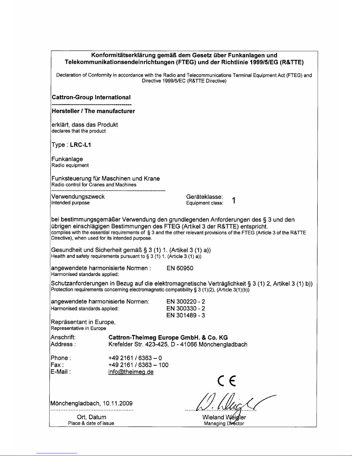
Declaration of Conformity .................................................................................................................................21
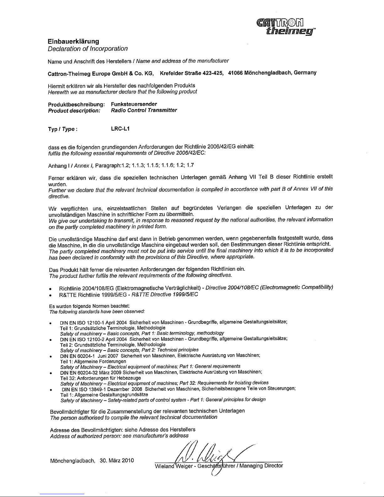
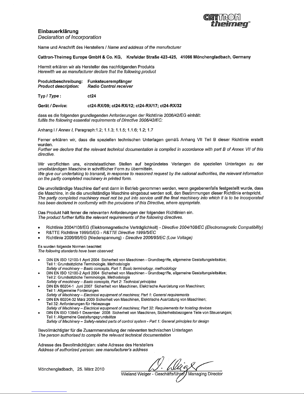
Declaration of Manufacturer .............................................................................................................................21
Manufacturer ISO-Certificate............................................................................................................................ 21
Page 4

User Manual LRC-L1
4 Subject to change without notice. Version 1.0.0 - 11/2010
1 Introduction
This manual includes general information concerning the operation of the radio remote control transmitter
series CattronControl LRC-L1. The information is of general nature and does not include system-specific
data. System-specific data is provided in the technical documentation accompanying the delivery of the
system.
For Information pertaining to the matching receiver unit, please refer to the separate user manual.
Page 5
User Manual LRC-L1
Version 1.0.0 - 11/2010 Subject to change without notice. 5
2 Safety Instructions
2.1 Used Symbols and Definitions for Warnings
!
Warning against hazardous situation
Warning against electrical voltage
!
Useful information
DANGER
Calls attention to a dangerous situation with high risk, severe injuries or death
possible.
WARNING Calls attention to a situation with medium risk, severe injuries possible.
CAUTION Calls attention to a situation with low risk, injuries or damage to the device possible.
NOTE Calls attention to important information.
2.2 General Information on Safety
• Persons under the influence of drugs and/or alcohol and/or other medicine that impairs their reaction may
not assemble, disassemble, install, put into operation, repair or operate the product.
• All conversions and modifications of an installation/system must conform to the relevant safety
requirements. Work on the electrical equipment must be performed only by qualified, authorized
personnel and in accordance with the relevant safety requirements.
• In the event of malfunctioning and visible defects or irregularities, the product must be stopped, switched off
and the relevant master switches must be switched off.
WARNING
!
Observe the statutory regulations and directives applicable for the intended purpose, e.g.:
• Accident prevention regulations
• Safety rules and directives
• Standards
• Generally applicable statutory and other binding regulations for accident prevention and
environmental protection and general safety and health requirements.
• The user must instruct his personnel accordingly.
• The Operating Manual must be kept permanently accessible at the place of use of the product.
• The personnel assigned to work on/with the product must have read and understood this Operating Manual
and the safety instructions.
• The safety instructions must, if necessary, be supplemented by the user with instructions concerning the
work organisation, work sequences, used personnel, etc.
• Only trained personnel may perform the work (maintenance and repair) with/on the product.
• It is the user’s responsibility to ensure that the product is always operated in a perfect condition and that all
applicable safety requirements and regulations are being observed.
• Product modifications may not be carried out without the consent of the manufacturer.
• In any event, only original spare parts from the manufacturer must be used.
• Periodical inspections and/or maintenance either required by law or prescribed in the user manual must be
carried out within the required intervals
Page 6
User Manual LRC-L1
6 Subject to change without notice. Version 1.0.0 - 11/2010
2.3 Use for Intended Purpose
The product must only be used in a technically perfect condition, by instructed personnel and subject to the
compliance with the applicable safety and accident prevention regulations. The product is electrical
equipment for use at the rated voltage shown on the type plate. A use for the intended purpose also requires
a compliance with the contents of this User Manual, particularly the therein described requirements and
instructions.
2.4 Improper Use
Certain work on / with, and use of the product is not permitted, in particular:
• Tampering with electrical equipment
• Mains supply connection deviating from the voltage / frequency data on the type plate
• Work on live components
• Incorrect operating
• Not permitted removal of covers
• Insufficient maintenance
• Failure to observe the operating temperature range
CAUTION
!
Damage of the device!
Do not immerse the transmitter unit in water!
Neglecting the above can result in danger for life and limb and / or may cause physical damage to the
product or the environment.
2.5 Safety Instructions for Assembly/Disassembly
Assembly / disassembly work may only be performed by qualified persons.
NOTE
!
Please assure suitable interference protection element of triggered electrical relays or valves.
Regard in particular the wiring of the crane’s main contactor and the manual radio switchover.
• The system must be isolated from the electrical power in accordance with the applicable regulations.
• User-specific regulations must be observed.
• Only suitable tools should be used.
• The installation area must be secured.
2.6 Operation of Radio Transmitter System Components with Identical System Address
For a safe operation, the radio control transmitter and the radio control receiver are uniquely paired by way
of a unique system address. This system address will only be assigned once by the manufacturer.
CAUTION
!
Conflict of Addresses
The operator must ensure that the system address is used for a single pair of transmitter and
receiver.
If more than one receiver or transmitter are used to control a machine or system, the operator
must take precautions that only a single transmitter is operated at each time.
In the event of a breach of this undertaking, the customer or the operator, respectively, is liable for
the resulting damage/ loss and he shall indemnify the manufacturer against all third-party liability
claims.
Page 7

User Manual LRC-L1
Version 1.0.0 - 11/2010 Subject to change without notice. 7
3 General
With a transmitter and a matching receiver unit a device such as a crane, a machine or a vehicle can be
radio controlled, thus avoiding the need for a wired connection between the human interface and the device
to be controlled. Over a number of different control elements in the transmitter housing commands to the
device are initiated by processing the signals and generating a RF signal that is cyclically transmitted to the
corresponding receiver unit.
3.1 Radio Transmission
The transmission between the transmitter and receiver is done by means of radio communication. With
regard to the actual radio frequency that is being used, there are several radio frequency bands available.
Within the respective frequency band a specific RF channel must be selected. Depending on the frequency
band a certain number of RF channels are available. For details regarding the available RF channels please
refer to the RF-Channel-Tables in this document. Transmitter and receiver must operate on the same RF
channel in order to be able to communicate
3.1.1 Continuous Transmission
One of the features of an industrial radio remote control system for safety-relevant applications such as
machine controls is that it is ensured, that a permanent connection between the transmitting and receiving
station exists. For this, the receiver unit constantly monitors the RF channel to verify that a communication
link exists. Should the receiver not receive a valid telegram for a certain period of time (PNH-Time), it will
automatically turn off, i.e. safety relays and command relays open. Depending on the application, the PNHTime varies from 0.5 s to 2.0 s.
3.1.2 Area of operation
In order to ensure optimum communication between the transmitter and the receiver unit, the transmitter
should be operated ideally with line of sight to the receiver or its antenna at all times. Any shielding by
metallic constructions should be avoided.
3.1.3 Radio Interference
Signals from other RF emitting sources might interfere with the radio communication between the transmitter
and receiver unit. If the radio link is affected by these sources, changing the RF channel or even the RF
band might be necessary.
3.2 System Address
In an industrial radio remote control system, each transmitter/receiver pair shares a common, unique system
address. This system address is contained in every telegram sent by the transmitter and is checked by the
receiver every time a RF signal is received. Only when the address in the telegram and the address stored in
the receiver match, the receiver processes a command. This is a safety measure to ensure that the receiver
will act only upon its assigned transmitter. The system address is stored in the TransKeys, please see below.
3.3 System Parameters
The system parameters including the system address and the selected RF channel are set by programming
the TransKey. It is a removable RFID (radio frequency identification device) located inside the transmitter
and receiver unit. It is programmed by the manufacturer.
NOTE
!
Please refer to the separate 'Configuration Data' documents for the specific system parameter
settings of your system.
Figure 1: Transmitter TransKey (black)
Page 8
User Manual LRC-L1
8 Subject to change without notice. Version 1.0.0 - 11/2010
4 Transmitter Unit
4.1 General
The LRC-L1 transmitter is a versatile transmitter unit that can be highly customized to meet the operational
requirements of many different applications. For this, a variety of control elements (joysticks, paddles, push
buttons, switches etc.) is available to tailor a transmitter layout for the individual application.
NOTE
!
For the system-specific transmitter layout for your application, please refer to the separate
engineering drawings you received with the delivery of the system.
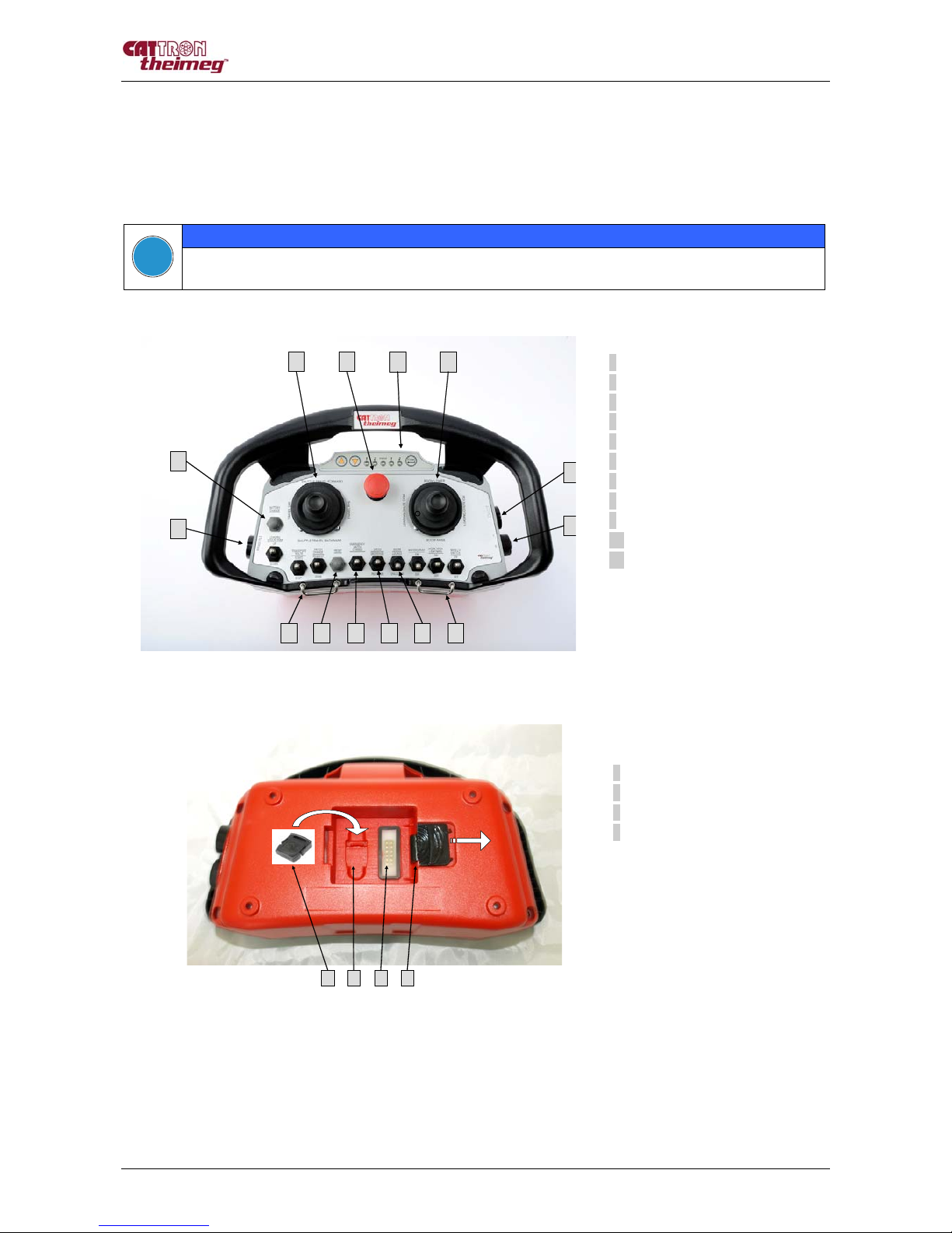
Figure 2: LRC-L1 Layout Example
Figure 3: LRC-L1 Battery Compartment
4.2 Display Option
The transmitter can optionally be equipped with a graphic display. This can be used to indicate certain
transmitter parameters such as the operating frequency, internal error messages, battery status and/or to
display feedback data that is being transmitted back from the corresponding radio receiver, which in this
case functions as a transceiver, receiving and transmitting data. For further information regarding the
feedback option, please refer to the system specific information provided with your system.
9
3
32
1
10
11
5
4
8 7 66
10
3 41
2
1 Stop Switch
2 LED/Push-button Panel
3 Joystick
4 Push Button Horn
5 Key switch: ON/OFF
6 Carrying Hook
7 Toggle Switch (maintained)
8 Toggle Switch (momentary)
9 Toggle Switch (maintained)
10 Push-button
11 Push-button
1 TransKey
2 TransKey Hollow
3 Battery and Programming Contacts
4 Battery Latch
Page 9

User Manual LRC-L1
Version 1.0.0 - 11/2010 Subject to change without notice. 9
4.3 Before turning on
⇒ Verify that the TransKey (black) is placed in the TransKey hollow inside the battery compartment
⇒ Insert a fully charged battery
NOTE
!
Batteries are shipped uncharged!
4.4 Turning the transmitter on (Standard)
⇒ STOP switch must be released and joysticks in Zero-position
⇒ Turn key switch to ON position 'I'
⇒ Status LED lights briefly red, then flashes green
⇒ The transmitter is turned on
NOTE
!
After the transmitter has been turned on, the safety relays in the receiver unit should be energized
and the receiver should be able to respond to commands initiated by the transmitter.
4.5 Turning the transmitter on with STOP switch check (only when requested by customer)
The transmitter can be configured so that for turning on the unit, the STOP switch must be activated once
before the transmitter goes into operation.
⇒ STOP switch must be released and joysticks in Zero-position
⇒ Turn key switch to ON position 'I'
⇒ Status LED lights red
⇒ Activate the Stop switch (Status LED light orange) and release within 10 seconds
⇒ Status LED flashes green
⇒ The transmitter is turned on
NOTE
!
After the transmitter has been turned on, the safety relays in the receiver unit should be energized
and the receiver should be able to respond to commands initiated by the transmitter.
4.6 Turning the transmitter off
⇒ Turn the transmitter off by bringing the key switch into the '0' position
NOTE
!
After the transmitter has been turned off, the safety relays and all other relays (in case of a relay
interface) in the receiver unit will be de-energized and the receiver will not be able to respond to any
commands initiated by the transmitter.
4.7 STOP Command
In the event of a dangerous situation, a STOP command can be initiated by pressing the STOP switch.
⇒ Press the STOP switch
⇒ Receiver unit is turned off
⇒ Transmitter unit is turned off
NOTE
!
After pressing the STOP switch, the safety relays and all other relays (in case of a relay interface) in
the receiver unit will be de-energized and the receiver will not be able to respond to any commands
initiated by the transmitter. The transmitter unit is turned off.
Page 10

User Manual LRC-L1
10 Subject to change without notice. Version 1.0.0 - 11/2010
4.8 Automatic Turn-off
The transmitter turns off automatically when the following events occur:
• Battery discharge protection (battery low)
• Internal failure (hardware or software)
4.9 Status LED
The status LED indicates the operation mode and error messages.
Status LED Condition Corrective Action
Flashes green 2.0-sec. interval Normal mode
⇒ No action required.
Flashes red 2.0-sec. interval Error indication
⇒ Refer to section Troubleshooting
Flashes red 0.5-sec. interval Pre-warning low voltage
⇒ Change the battery within
10 minutes.
Page 11

User Manual LRC-L1
Version 1.0.0 - 11/2010 Subject to change without notice. 11
5 Battery & Battery Charger
5.1 Connecting the Battery Charger
The processor-controlled battery charger can be configured with exchangeable plugs for the main power
supply. Before using the charger, ensure that the appropriate plug for your country has been inserted into the
unit. Should this not be the case and the plug needs changing, follow these steps:
⇒ In order to change the plug, shift the spring-loaded locking mechanism on the back of the charger unit in
the indicated direction.
⇒ Insert the desired exchangeable plug into the charger unit until it audibly clicks and is locked into place.
The ‘Power’ LED will light up and indicate the ready condition as soon as the charger unit is connected to
the mains supply.
⇒ Connect the charger with the charger cradle by inserting the plug on the secondary side of the charger
into the matching socket in the charger cradle.
Figure 4: Charger unit with exchangeable plugs Figure 5: Charger unit with cradle
DANGER
!
Electric shock
Do not open the charger. The charger must be protected against moisture and rain in order to
exclude the fire hazard or an electric shock. The charger must only be operated in dry indoor
spaces. Do not use the charger if the housing or mains plug is damaged! Contact the customer
service department of Cattron-Theimeg Europe GmbH & Co. KG.
5.2 Charger Status Indication
Indication Description
“Power” (1)
red LED
Permanent light indicates that the charger is ready for operation. Lights up as soon
as the charger is connected to the mains supply.
”Charge” (2)
red LED
Permanent light indicates the charging after contacting the battery.
”Ready” (3)
green LED
Permanent light indicates that the battery is charged. The green LED switches to
blinking mode after approximately 2 minutes = pulse trickle charging.
During testing mode, the LED blinks in conjunction with the "Charge" LED.
“Discharge” (4)
yellow LED
After pressing the discharge button for approx. 2 s, permanent light indicates the
discharging. Simultaneously, the ‘Ready’ LED blinks for approximately 1 minute to
indicate the testing phase.
Discharge button (5) Pressing the discharge button for approx. 2 s starts discharging of the battery.
Page 12

User Manual LRC-L1
12 Subject to change without notice. Version 1.0.0 - 11/2010
5.3 Charging the Battery
WARNING
!
Explosion hazard
Only use original batteries of the manufacturer (Nickel / Metal Hydride [NiMH] batteries). Other
batteries may explode when charged with this device.
⇒ Put the battery into the cradle. The red LED “Charge” lights up to indicate that the unit is charging mode.
During testing mode, the green LED “Ready” flashes for approximately 1 minute. Should after this time
the red LED “Charge” be off and the LED "Ready" be flashing, the battery is not contacted correctly.
Remove the battery and insert it again.
⇒ When the battery is charged, the red “Charge” LED turns off and the “Ready” LED lights up.
⇒ The device switches automatically to pulse trickle charge.
⇒ After about two minutes, the LED indication changes to green flashing. The battery may be used either
immediately or may be left in the cradle until it is needed.
During the charging process, the status of the battery is constantly monitored and automatically terminated
when the charging process is completed. Overcharging is therefore prevented.
NOTE
!
The battery charging time can take up to 3 hours.
NOTE
!
Batteries may only be charged at a maximum ambient temperature of 40°C.
5.4 Defective Battery
Before the charging process begins, the battery is tested for defects. If the green “Ready” LED lights up
immediately after inserting the battery into the cradle and if the red “Charge” LED blinks from time to time
after 20 s, the battery is defective and can no longer be used. Replace the battery in this case.
NOTE
!
Used batteries shall be disposed according to local regulations.
5.5 Battery Discharging
NOTE
!
If batteries are discharged only partly and over a long period, it is recommend to discharge the
batteries completely from time to time to preserve its capacity.
Press the yellow Reset key to discharge the battery.
By pressing the discharge button, the battery can be discharged prior to charging. Afterwards the battery
charger switches to charge-mode automatically. If the battery is fully charged, the device switches over to
pulse trickle charging.
Page 13

User Manual LRC-L1
Version 1.0.0 - 11/2010 Subject to change without notice. 13
6 RF Channel Change
In order to ensure an interference-free operation of a radio control system it may be necessary to change the
RF channel preset by the manufacturer. Changing the RF channel can become necessary due to
interference or in the event that a RF channel is already in use by another system. The RF channel can be
changed either by reprogramming the TransKey (external programming) or by using the RF channel
selection feature of the transmitter unit as described below.
NOTE
!
The features described in this section are available with standard transmitter units, furnished with
a key switch and horn push-button. Should these control elements not be available, these features
may not function either in part or entirely.
6.1 Working Principle
The operating RF channel of the transmitter can be changed, using the push buttons in the LED/Push button
panel. For this, the transmitter must first be brought into Programming Mode. The respective RF channels
are displayed by the 4 LEDs located to the left and right of the STATUS LED. Each RF channel has been
assigned a specific colour code, shown in the 'RF Channel Tables'.
Figure 6: LED/Push-button panel
6.2 Activating the Programming Mode
Before the RF channel can be changed, the transmitter unit must be brought into 'Programming Mode'
⇒ With the transmitter unit turned off, hold the horn push-button down and turn the unit on by turning the key
switch
⇒ Hold the horn push-button for approximately 5 seconds until the Status LED changes from permanent red
to fast blinking red
⇒ Release the horn push-button within 3 seconds
⇒ The transmitter is now in 'Programming Mode', the currently selected RF channel is indicated via the 4
LEDs on the panel.
6.3 Changing the RF Channel
⇒ Bring the transmitter unit into Programming Mode (see above). If already in programming mode continue
with the next step.
⇒ Actual RF Channel is displayed by LEDs, see RF Channel Tables
⇒ Select the desired RF Channel by pressing
, for fast hold depressed for > 2 seconds
⇒ Select and save the RF Channel with
EnterEnter
⇒ Status LED changes from blinking red to continuous red
⇒ Turn transmitter unit off with key switch
STATUS
1 2 1
RF Channel
up (+)
RF Channel
down (-)
RF-Channel
Indication
STATUS
1 2 1
RF Channel
up (+)
RF Channel
down (-)
RF-Channel
Indication
Page 14

User Manual LRC-L1
14 Subject to change without notice. Version 1.0.0 - 11/2010
6.4 Receiver Synchronisation to new RF Channel
The transmitter features an automatic RF channel synchronisation. It will automatically find its corresponding
transmitter and adjust its RF channel to the new channel.
NOTE
!
After the first activation of the transmitter, following a RF channel change, it can take up to 1
minute before the receiver will have adjusted itself to the new RF channel and is ready for
operation.
6.5 Re-Activating the TransKey RF Channel
The RF channel programmed by the factory remains stored in the TransKey and can be re-activated if
required.
⇒ Bring the transmitter unit into programming mode (see above). If already in programming mode continue
with the next step.
⇒ Holding both and pressing
EnterEnter
re-activates the RF Channel stored in the TransKey stored.
⇒ The STATUS LED changes from blinking red to permanent red, all other LEDs are off.
⇒ In order to take the transmitter into operation it must be turned off and on again.
⇒ It now transmits on the RF channel stored in the TransKey.
6.6 Indication of the Interference Field Strength
This is a helpful feature to determine whether other systems are transmitting on the currently selected RF
channel. The level of interference, i.e. the field strengths of such systems can be indicated. The interference
field strength is displayed via the Status LED in combination with the internal acoustic buzzer signal.
In the event that there is interference on the selected RF channel, it is recommended that a different, free RF
channel is selected.
NOTE
!
This feature is not available for the 869 MHz frequency band.
⇒ Bring the transmitter unit into programming mode (see above). If already in programming mode continue
with the next step.
⇒ Press the HORN push-button briefly.
⇒ If there is any interference, its severity will be indicated by a combination of the STATUS LED and the
internal buzzer for 3 seconds. There are 3 levels. See the below table.
⇒ Should there be no interference, exit the programming mode by turning the unit off.
Status LED
Buzzer
Interference
Corrective action
green no sound low None required
Status LED
Buzzer Interference Corrective action
orange no sound medium If possible change the RF channel
Status LED
Buzzer Interference Corrective action
red sounding high The RF channel must be changed
NOTE
!
The field strength received from other transmitters should be as low as possible in order to avoid
possible interference of the radio path between the transmitter and the receiver.
Page 15

User Manual LRC-L1
Version 1.0.0 - 11/2010 Subject to change without notice. 15
6.7 Automatic RF Channel Selection Feature
The transmitter unit has a feature, which allows to automatically scanning all RF channels in the respective
frequency range for interference. During the scan process, the transmitter performs field strength
measurements of each individual channel and creates an internal, virtual channel proposal list. Upon
completion of the scan process, the RF channel with the lowest interference field-strength is displayed (4
LEDs) as the recommended channel. Either this recommended RF channel can be accepted or the next
channel on the list of proposed channels can be selected.
NOTE
!
This function is not available for the 869 MHz frequency band.
⇒ Bring the transmitter unit into programming mode (see above). If already in programming mode continue
with the next step.
⇒ Press HORN push-button for 5 Seconds until a sound is audible and release it.
⇒ RF Band scanning starts, indicated by the STATUS LED changing from red to blinking orange.
⇒ RF channel LEDs are changing according to the RF channel Tables.
⇒ Once the scanning process is completed a sound is audible, the STATUS LED changes to blinking green.
⇒ The RF channel with the lowest interference is displayed. It can either be accepted and saved by
EnterEnter
, or
alternatively see below.
⇒ STATUS LED changes from blinking green to continuous red.
⇒ Turn off Transmitter.
Alternatively:
⇒ With the list of recommended RF Channels can be viewed.
⇒ Select an appropriate RF channel, confirm and save with
EnterEnter
.
⇒ STATUS LED changes from blinking green to continuous red.
⇒ Turn off Transmitter.
Page 16

User Manual LRC-L1
16 Subject to change without notice. Version 1.0.0 - 11/2010
6.8 RF Channel Tables
Depending on the country or region of the world, the system must operate in a for the application approved
RF frequency band. Following are the available frequency bands with the available RF channels in each
frequency band. The RF channels have been colour coded to display them via the 4 LEDs located on the
push-button panel of the transmitter unit.
NOTE
!
When changing the RF channel it must be ensured that country-specific regulations regarding
frequency range and channel are being observed
6.8.1 RF Channel Table 418/419 MHz Band
STATUS
1 2
1 2
STATUS
1 2
1 2
Channel Frequency/MHz 1 2 3 4
1 418.9500 - - green green
2 418.9750 - - green orange
3 419.0000 - - orange 4 419.0250 - - orange red
5 419.0500 - - orange green
6 419.0750 - - orange orange
7 419.1000 - red - 8 419.1250 - red - red
9 419.1500 - red - green
10 419.1750 - red - orange
11 419.2000 - red red 12 419.2250 - red red red
13 419.2500 - red red green
419.2750 - red red orange
6.8.2 RF Channel Table 447 MHz Band
STATUS
1 2
1 2
STATUS
1 2
1 2
Channel Frequency/MHz 1 2 3 4
1 447.8625 - orange - red
2 447.8750 - orange - green
3 447.8875 - orange - orange
4 447.9000 - orange red 5 447.9125 - orange red red
6 447.9250 - orange red green
7 447.9375 - orange red orange
8 447.9500 - orange green -
9 447.9625 - orange green red
10 447.9750 - orange green green
11 447.9875 - orange green orange
6.8.3 RF Channel Table 869 MHz Band
STATUS
1 2
1 2
STATUS
1 2
1 2
Channel Frequency/MHz 1 2 3 4
0 * 869.850 - - - -
1 869.800 - - - red
2 869.900 - - - green
3 869.535 - - - orange
(*)This channel should not be used if existing systems are already operating
on channels 1 and/or 2 and are in close proximity.
Page 17

User Manual LRC-L1
Version 1.0.0 - 11/2010 Subject to change without notice. 17
6.8.4 RF Channel Table 433/434 MHz Band
STATUS
1 2
1 2
STATUS
1 2
1 2
Channel Frequency/MHz 1 2 3 4
1 433.0775 - - - red
2 433.1025 - - - green
3 433.1275 - - - orange
4 433.1525 - - red 5 433.1775 - - red red
6 433.2025 - - red green
7 433.2275 - - red orange
8 433.2525 - - green -
9 433.2775 - - green red
10 433.3025 - - green green
11 433.3275 - - green orange
12 433.3525 - - orange 13 433.3775 - - orange red
14 433.4025 - - orange green
15 433.4275 - - orange orange
16 433.4525 - red - 17 433.4775 - red - red
18 433.5025 - red - green
19 433.5275 - red - orange
20 433.5525 - red red 21 433.5775 - red red red
22 433.6025 - red red green
23 433.6275 - red red orange
24 433.6525 - red green 25 433.6775 - red green red
26 433.7025 - red green green
27 433.7275 - red green orange
28 433.7525 - red orange 29 433.7775 - red orange red
30 433.8025 - red orange green
31 433.8275 - red orange orange
32 433.8525 - green - 33 433.8775 - green - red
34 433.9025 - green - green
35 433.9275 - green - orange
36 433.9525 - green red 37 433.9775 - green red red
38 434.0025 - green red green
39 434.0275 - green red orange
40 434.0525 - green green 41 434.0775 - green green red
42 434.1025 - green green green
43 434.1275 - green green orange
44 434.1525 - green orange 45 434.1775 - green orange red
46 434.2025 - green orange green
47 434.2275 - green orange orange
48 434.2525 - orange - 49 434.2775 - orange - red
50 434.3025 - orange - green
51 434.3275 - orange - orange
52 434.3525 - orange red 53 434.3775 - orange red red
54 434.4025 - orange red green
55 434.4275 - orange red orange
56 434.4525 - orange green 57 434.4775 - orange green red
58 434.5025 - orange green green
59 434.5275 - orange green orange
60 434.5525 - orange orange 61 434.5775 - orange orange red
62 434.6025 - orange orange green
63 434.6275 - orange orange orange
64 434.6525 red - - 65 434.6775 red - - red
66 434.7025 red - - green
67 434.7275 red - - orange
68 434.7525 red - red 69 434.7775 red - red red
Page 18

User Manual LRC-L1
18 Subject to change without notice. Version 1.0.0 - 11/2010
6.8.5 RF Channel Table 915 MHz Band (U.S.A.)
STATUS
1 2
1 2
STATUS
1 2
1 2
Channel Frequency/MHz 1 2 3 4
1 903.0 - - - red
2 904.2 - - - green
3 905.4 - - - orange
4 906.6 - - red 5 907.8 - - red red
6 909.0 - - red green
7 918.6 - - red orange
8 919.8 - - green -
9 921.0 - - green red
10 922.2 - - green green
11 923.4 - - green orange
12 903.2 - - orange 13 904.4 - - orange red
14 905.6 - - orange green
15 906.8 - - orange orange
16 908.0 - red - 17 909.2 - red - red
18 918.8 - red - green
19 920.0 - red - orange
20 921.2 - red red 21 922.4 - red red red
22 923.6 - red red green
23 903.4 - red red orange
24 904.6 - red green 25 905.8 - red green red
26 907.0 - red green green
27 908.2 - red green orange
28 909.4 - red orange 29 919.0 - red orange red
30 920.2 - red orange green
31 921.4 - red orange orange
32 922.6 - green - 33 923.8 - green - red
34 903.6 - green - green
35 904.8 - green - orange
36 906.0 - green red 37 907.2 - green red red
38 908.4 - green red green
39 909.6 - green red orange
40 919.2 - green green 41 920.4 - green green red
42 921.6 - green green green
43 922.8 - green green orange
44 924.0 - green orange 45 903.8 - green orange red
46 905.0 - green orange green
47 906.2 - green orange orange
48 907.4 - orange - 49 908.6 - orange - red
50 919.4 - orange - green
51 920.6 - orange - orange
52 921.8 - orange red 53 923.0 - orange red red
54 924.2 - orange red green
55 904.0 - orange red orange
56 905.2 - orange green 57 906.4 - orange green red
58 907.6 - orange green green
59 908.8 - orange green orange
60 918.4 - orange orange 61 919.6 - orange orange red
62 920.8 - orange orange green
63 922.0 - orange orange orange
64 923.2 red - - 65 924.4 red - - red
Page 19

User Manual LRC-L1
Version 1.0.0 - 11/2010 Subject to change without notice. 19
7 Technical Data
7.1 Technical Data Transmitter
7.2 Technical Data Battery Charger
Transmitter series
LRC-L1
Frequency bands
335 MHz
418 MHz
433 MHz
447 MHz
869 MHz
915 MHz
Transmission speed
4.8 - 20 kbps
Transmitter output power
< 5 mW / < 10 mW
depending on frequency band
Antenna
internal
System addresses
24 bit
Power-saving mode
automatic switch-off
(configurable 0 – 30 minutes)
Power supply
Autonomy
NiMH, 4.8 V / 1600 mAh,
Quick-swap rechargeable battery
>12 h @ 100% duty cycle
Control elements
variable
Indication
1 Status LED for status and error indication
4 Multi-LEDs for RF channel selection
1 Buzzer
LCD Display (optional)
Weight
approximately 1.6 kg
Dimensions (W x H x D)
320 x 255 x 185 mm
Housing
Plastic, standard colours: red/grey
Operating temperature
-20 ºC ... +60 ºC
Protection class
IP 65
STOP command
EN 954-1 Category 3 for all safety relevant functions
EN 13849-1 Performance Level d
Type
Processor-controlled charger
Part number
BT 097-00303
Dimensions (W x D x H) /
60 x 90 x 120 mm
Power supply
Primary: 100-240 VAC, 50/60 Hz, 17 VA, 300 mA
Secondary: 1.45 - 14.5 VDC. 800 mA, 9.6 VA
Page 20

User Manual LRC-L1
20 Subject to change without notice. Version 1.0.0 - 11/2010
8 Troubleshooting
8.1 Transmitter Error Indication
Should an error occur, the Status-LED in the LED/Push-button panel of the transmitter unit will indicate the
cause of the error. This is done via a number of different blink sequences. The sequences and the relevant
corrective actions are listed below.
LED
Number of
flashes
Description Corrective Action
2
TransKey cannot be read
Plug in TransKey
3
Error detected in TransKey
configuration
Have the TransKey-configuration checked by
Cattron-Theimeg.
4
Low-voltage condition of the mains
supply detected
Change main board.
5
Switch-on sequence not carried out
correctly
Switch the transmitter off and on again, following
the correct switch-on sequence.
6
Fault during reading control elements
Replace control element or main board.
7
Internal communication error between
RF-module and main board
Replace RF-module or main board.
8
General system fault
Replace main board.
9
Low-voltage detection shortly after
switch-on
Change or charge battery.
10
Hardware fault
Replace main board.
Page 21

User Manual LRC-L1
Version 1.0.0 - 11/2010 Subject to change without notice. 21
9 Appendices
Declaration of Conformity
Declaration of Manufacturer
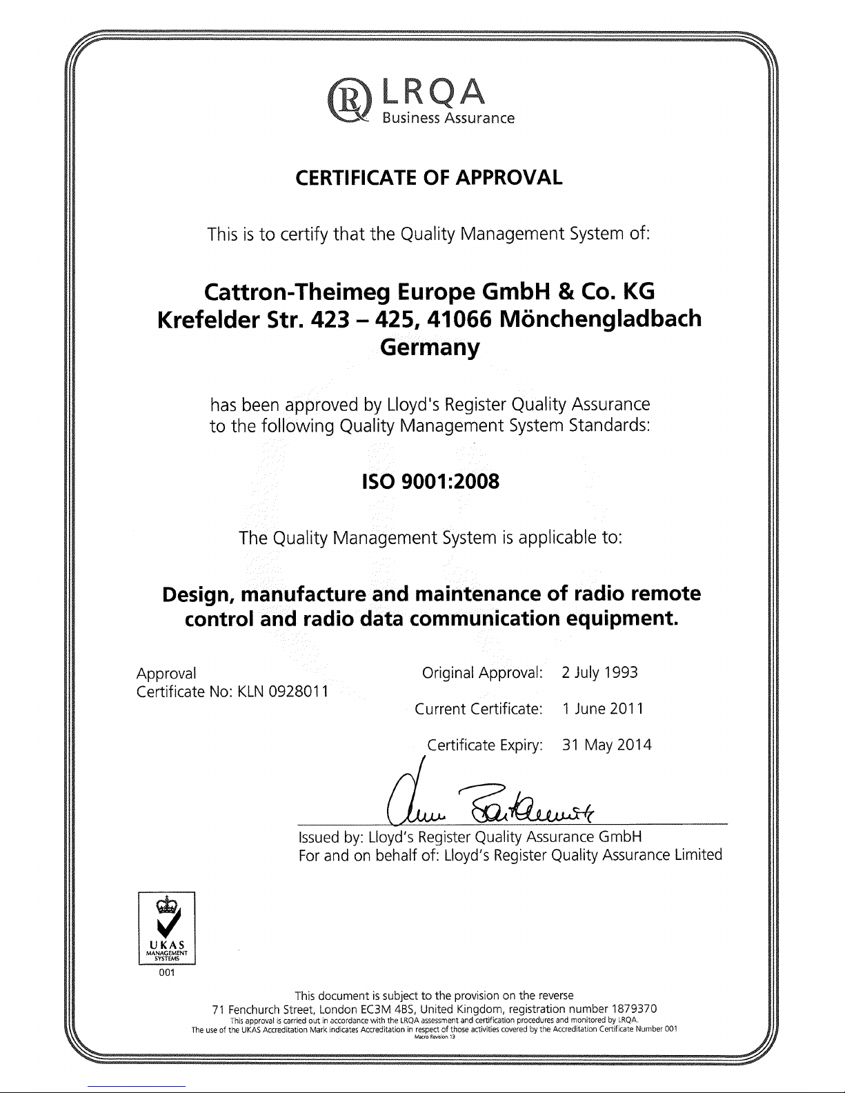
Manufacturer ISO-Certificate
Page 22
Page 23
Page 24
Page 25
Page 26

User Manual LRC-L1
22 Subject to change without notice. Version 1.0.0 - 11/2010
 Loading...