

Page 1

Operating Manual
Radio Remote Control System
Edition 04/2007 US, Version A001, Excalibur, Subject to Technical Changes Page: 1
Page 2

Cattron-Group International .
58 West Shenango Street
Sharpsville, PA 16150 USA
Tel: (724) 962 -3571
Fax: (724) 962 -4310
mail@cattron-theimeg.com
www.cattron-theimeg.com
Copyright:
This technical document or parts thereof may not be reprinted or copied – except for own use
for the operation of the radio remote control system – without the written permission of
Cattron -Theimeg Europe GmbH & Co. KG. It may not be made accessible to a third party.
The copying of the described radio remote control system is not permitted.
Edition 04/2007 US, Version A001, Excalibur, Subject to Technical Changes 2
Page 3

Table of Contents
1. Safety Instructions....................................................................................................................................................3
1.1 General Information on Safety...................................................................................................................................3
1.2 Operation of Radio Remote Control System Components with Identical System Address..................4
1.3 Use for Intended Purpose............................................................................................................................................4
1.4 Improper Use...................................................................................................................................................................4
1.5 Safety Instructions for Assembly/Disassembly....................................................................................................4
2. Installation and Preparation................................................................................................................................. 5
2.1 Battery Charger...............................................................................................................................................................5
2.2 Receiver.............................................................................................................................................................................6
2.2.1 Selection of the Place of In stallation..................................................................................................................6
2.2.2 Inserting the TransKey in the Receiver............................................................................................................6
2.2.3 Installing the Receiver ............................................................................................................................................7
2.2.4 Electrical Connection of the Receiver...............................................................................................................7
2.3 Transmitter........................................................................................................................................................................7
2.3.1 Inserting the Rechargeable Battery into the Transmitter:...........................................................................7
2.3.2. Transmitter Labelling..............................................................................................................................................7
3. Putting into Operation.............................................................................................................................................8
3.1 Transmitter........................................................................................................................................................................8
3.1.1 Transmitter Variants ................................................................................................................................................8
3.1.2 Switching On the Transmitter:.............................................................................................................................8
3.1.3 Transmitter Blink Sequences [Status Indications] of the Status-LED....................................................9
3.1.4 Switching Off the Transmitter:.............................................................................................................................9
3.1.5 TransKey ..................................................................................................................................................................... 9
3.2 Receiver...........................................................................................................................................................................10
3.2.1 Receiver with 9 Command Relays ...................................................................................................................10
3.2.2 Receiver with 12/17 Command Relays ..........................................................................................................10
3.2.3 Relay Status Indication.........................................................................................................................................11
3.2.4 Power und Status Indication...............................................................................................................................11
4. Charging the Transmitter Batteries with the Battery Charger ...........................................................12
4.1 Functional Overview ....................................................................................................................................................12
4.2 Indication on the Charger..........................................................................................................................................12
4.3 Charging ..........................................................................................................................................................................13
4.4 Trickle Charging............................................................................................................................................................13
4.5 Discharging.....................................................................................................................................................................13
4.6 Defective Battery..........................................................................................................................................................13
5. Maintenance...............................................................................................................................................................14
5.1 Cleaning the Transmitter ............................................................................................................................................14
6. Appendix.....................................................................................................................................................................15
A-1 Technical Data of the Transmitter...........................................................................................................................15
A-2 Technical Data of the Receiver................................................................................................................................16
A-3 Technical Data of the Charger.................................................................................................................................16
B-1 Fault Messages of the Transmitter.........................................................................................................................17
B-2 Fault Messages of the Receiver..............................................................................................................................17
C-1 Mounting Drawings ......................................................................................................................................................18
C-2 Connection Plan for Receiver with 9 Command Relays .................................................................................19
C-3 Connection Plan for Receiver with 12/17 Command Relays ........................................................................20
D-1 Spare Part List
Edition 04/2007 US, Version A001, Excalibur, Subject to Technical Changes Page: 1
Page 4

Information to the User regarding FCC Compliance:
1 - Changes or modifications not expressly approved by the manufacturer could void the
user's authority to operate the equipment.
2 - This class A digital apparatus complies with Industry -Canada ICES-003 standards.
3 - This device complies with part 15 of the FCC Rules. Operation is subject to the
following two conditions:
(1) This device may not cause harmful interference, and
(2) This device must accept any interference received, including interference that
may cause undesired operation.
NOTE: This equipment has been tested and found to comply with the limits for a Class A
digital device, pursuant to part 15 of the FCC Rules. These limits are designed to
provide reasonable protection against harmful interference. This equipment
generates, uses, and can radiate radio frequency energy and, if not installed and
used in accordance with the instruction manual, may cause harmful interference to
radio communications. Operation of this equipment in a residential area is likely to
cause harmful interference in which case the user will be required to correct the
interference at his/her own expense.
Edition 04/2007 US, Version A001, Excalibur, Subject to Technical Changes Page: 2
Page 5

1. Safety Instructions
1.1 General Information on Safety
Persons under the influence of drugs and/or alcohol and/or other medicine that impairs the reaction may
not assemble, disassemble, install, put into operation, repair or operate the product.
All conversions and modifications of an installation/system must conform to the relevant safety
requirements. Work on the electrical equipment may only be performed by qualified, authorized personnel
and in accordance with the relevant safety requirements.
In the event of malfunctioning, the product must be stopped, switched off and the relevant master switches
must be switched off.
Warning!
Do not fail to observe:
the statutory regulations and directives applicable for the intended purpose, e.g.:
• Accident prev ention regulations
• Safety rules and directives
• Generally applicable statutory and other binding regulations for accident prevention
and environmental protection and general safety and health requirements.
The user must instruct his personnel accordingly.
The Operating Manual must be kept permanently accessible at the place of use of the product.
The personnel assigned to work on/with the product must have read and understood this Operating
Manual and the safety instructions.
The safety instructions must, if necessary, be supplemented by the User with instructions concerning the
work organisation, work sequences, used personnel, etc.
Only trained personnel may perform the work with/on the product.
The User must ensure that the product is always operated in a perfect condition and that all applicable
safety requirements and regulations are observed.
The product must be put out of operation immediately when faults or functional irregularities are identified.
Product modifications, conversions or add-ons can impair the safety and may not be made without the
consent of the manufacturer.
Use only original spare parts from the manufacturer.
Observe the intervals for periodic inspection/maintenance mentioned in this Operation Manual or
otherwise mandatory.
Edition 04/2007 US, Version A001, Excalibur, Subject to Technical Changes Page: 3
Page 6

1.2 Operation of Radio Remote Control System Components with Identical System
Address
For a safe operation, the radio control transmitter and the radio control receiver are uniquely paired by way
of an unique system address. This system address will only be assigned once by the manufacturer.
For further information, refer to the applicable standards and regulations, e.g. for crane control: [BGR 149
respectively DIN EN 60204-32]. It must be ensured that only one transmitter-receiver pair can be operated
with a sp ecific system address.
An identical system address will not be assigned again by Cattron-Theimeg Europe GmbH & Co.KG
unless this is expressly requested by the Customer.
In cases where several transmitters and/or receivers for the control of a machine are available,
precautions must be taken to ensure that only 1 transmitter, respectively 1 receiver, can be used at any
one time.
In the case of a supply of radio remote control system components with an identical system address,
Cattron-Theimeg Europe GmbH & Co.KG ships components with warning instructions for the user that
must be affixed to the devices.
The customer undertakes to ensure that no other radio remote control system with the same system
address is operated. In the event of a breach of this undertaking, the customer is liable for the resulting
damages/loss and he shall indemnify the manufacturer against all third-party liability claims.
1.3 Use for Intended Purpose
The product may only be used in a technically perfect condition, by instructed perso nnel and subject to the
compliance with the applicable safety and accident prevention regulations. The product is electrical
equipment for use at the rated voltage shown on the type plate. A use for the intended purpose also
requires a compliance with the contents of this Operating Manual, particularly the therein described
requirements and instructions.
1.4 Improper Use
Certain work on/with, and use of, the product is not permitted:
• tampering with electrical equipment,
• mains supply connection deviating from the voltage/frequency data on the type plate,
• work on live components,
• incorrect operating,
• improper use of the product,
• not permitted removal of covers,
• insufficient maintenance,
• failure to observe the operating temperature range.
A failure to observ e the above can result in danger for life and limb and/or damage to the product.
1.5 Safety Instructions for Assembly/Disassembly
Assembly/disassembly work may only be performed by qualified persons.
The system must be isolated from the electrical power in accordance with the applicable regulations. Userspecific rules must be observed. Only suitable tools may be used. Unauthorised access to the assembly
area must be prevented.
Edition 04/2007 US, Version A001, Excalibur, Subject to Technical Changes Page: 4
Warning!
Please assure suitable interference protection element of triggered
electrical relay or valves.
Page 7

2. Installation and Preparation
2.1 Battery Charger
Edition 04/2007 US, Version A001, Excalibur, Subject to Technical Changes Page: 5
Page 8
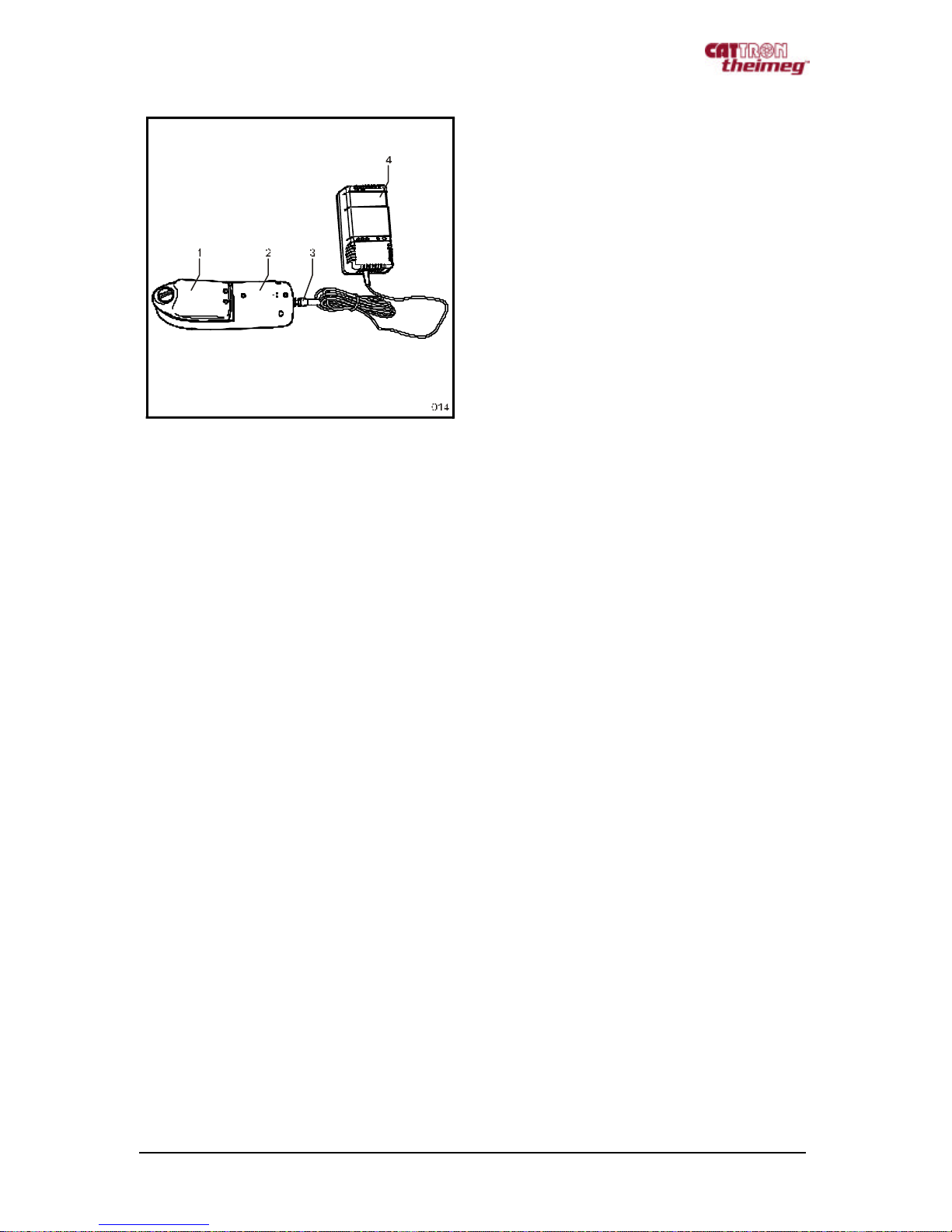
Description
1 Rechargeable battery
2 Charging tray
3 Charging plug
4 Charger
⇒ Connect the charger to the mains supply
⇒ Connect the charging tray with the charger
⇒ Insert the rechargeable battery into the charging tray
The electrical mains adapter [100 -240 VAC] and the set of exchangeable plugs that come with the
equipment make it possible to use the charger worldwide.
⇒ To change the plug, please shift the unlocking mechanism on the back of the charger in the
direction of the arrow.
⇒ Insert the correct exchangeable plug into the charger until it audibly clicks and is locked in place.
The ‘Power’ LED will light up and indicate the ready condition as soon as the charger is connected
to the mains supply.
Edition 04/2007 US, Version A001, Excalibur, Subject to Technical Changes Page: 1
Page 9

2.2 Receiver
Warning!
The machine or system to be controlled must be switched off and secured against an
accidental switch-on before the start of the assembly.
Only qualified personnel may perform the work.
2.2.1 Selection of the Place of Installation
The standard receiver is shipped with an internal antenna. Ideally, the transmitter and receiver should
be sited to allow a visual contact between them in order to ensure a perfect communication Screening
by metal construction should be avoided.
Note!
The receiver can be optionally equipped with an external antenna.
2.2.2 Inserting the TransKey in the Receiver
If not already inserted in the receiver, insert the receiver TransKey [yellow], [1] in its holder.
Warning!
The transmitter and receiver TransKeys may not be swapped.
The transmitter TransKey is black.
The receiver TransKey is yellow.
A swapping of the TransKeys results in a fault indication in the transmitter and in the
receiver [see LED blink sequences]. The system will not go into operation.
Edition 04/2007 US, Version A001, Excalibur, Subject to Technical Changes Page: 6
Page 10

2.2.3 Installing the Receiver
To install the receiver, please use the mounting drawings contained in the appendix.
2.2.4 Electrical Connection of the Receiver
For the electrical connection to the mains supply and the assignment of the contact terminals please
refer to the connection plan in the appendix and the attached interface plan.
The system can be put into operation after the completion of all installation work.
2.3 Transmitter
2.3.1 Inserting the Rechargeable Battery into the Transmitter:
⇒ Insert the charged battery [2] into the transmitter [3] (the transmitter should point downwards),
⇒ Lock the battery in place by turning the knob [1].
The transmitter is now ready for use.
Warning!
The radio remote control system is shipped with a discharged battery.
The battery must be correctly charged before the system is put into operation.
2.3.2. Transmitter Labelling
The transmitter can be given an individual labelling to suit the specific use of the radio remote control
system. For this purpose, the system comes with a sheet of self -adhesive labels that can be affixed in
the label fields on the transmitter.
An optional second labelling sheet is available for specific applications.
Edition 04/2007 US, Version A001, Excalibur, Subject to Technical Changes Page: 7
Page 11

3. Putting into Operation
3.1 Transmitter
3.1.1 Transmitter Variants
Excalibur transmitters come in two housing sizes equipped with 6, 8, 10 or 12 2-step pushbuttons
3.1.2 Switching On the Transmitter:
Description
1 Status LEDs
2 Function pushbuttons
3 STOP pushbutton
4 ON pushbutton [1st step],
Horn pushbutton [2nd step]
5 Battery compartment [on the rear side
of the charger]
6 TransKey
⇒ The black Transkey [6], must be inserted
Perform the switch-on sequence as follows
⇒ Press the ON pushbutton [4] once – Status LED [1] lights red,
⇒ Press the STOP pushbutton [3] once [1st + 2nd step] – Status LED [1] lights orange,
⇒ Press the ON pushbutton [4] again once – Status LED [1] lights green,
[The switch -on sequence must be completed within 10 seconds]
The Transmitter can now be used to control the system.
Note!
The function of the pushbutton [2] is dependent on the program stored in the TransKey
[6].
The transmitters have two-step pushbuttons. The 1st pressing point [1st step] is followed
by a second pressing point (2nd step).
See example pushbutton 4: ON [1st step], Horn [2nd step]
Warning!
Do not swap the transmitter/receiver
TransKey!
Edition 04/2007 US, Version A001, Excalibur, Subject to Technical Changes Page: 8
Page 12

3.1.3 Transmitter Blink Sequences [Status Indications] of the Status-LED
Status Indications Status LED Action
Normal operation Blinks green at 1.25 s intervals. —
Early warning of low
voltage
Blinks red at 1.0 s intervals. Insert a charged battery within 10
min. or charge the battery.
3.1.4 Switching Off the Transmitter:
⇒ Press 1st step of STOP pushbutton [1] [OFF] or,
⇒ Press 2nd step of the STOP pushbutton [1]
3.1.5 TransKey
The system -specific parameters are activated with the data stored in the TransKey. A label with the ID
address is affixed to each TransKey.
Warning!
Transmitter and receiver TransKeys must not be swapped.
The transmitter TransKey is black.
The receiver TransKey is yellow.
A swapping of the TransKeys results in a fault indication in the transmitter and in the
receiver [see LED blink sequences]. The system will not go into operation.
Edition 04/2007 US, Version A001, Excalibur, Subject to Technical Changes Page: 9
Page 13

3.2 Receiver
3.2.1 Receiver with 9 Command Relays
3.2.2 Receiver with 12/17 Command Relays
Description
1 Power and Status LEDs
2 Terminal strip for the relay contacts
3 K0 relay fuse
4 K0 relay connector
5 Supply voltage fuse
6 Supply voltage connector
Description
1 Power and Status LEDs
2 Terminal strip for the relay contacts
3 K0 relay fuse
4 K0 relay connector
5 Supply voltage fuse
6 Supply voltage connector
Edition 04/2007 US, Version A001, Excalibur, Subject to Technical Changes Page: 10
Page 14

3.2.3 Relay Status Indication
Each relay has an LED on the pcb for display of the relay status [only visible with removed housing
cover].
3.2.4 Power und Status Indication
The receiver has 5 externally visible LEDs that display the current system status.
LED Description
1: Power On Lights orange:
as soon as the receiver has voltage
2: Without function
3: RF Reception Lights green:
if valid data from the transmitter is rece ived and both K0 relays are
activated.
Lights orange:
if valid data from the transmitter is received and the K0 relays are
deactivated.
Lights red:
if data from another transmitter [with invalid address] is received.
OFF,
if no transmitter is identified .
4: Command Lights green:
if commands are received [normal condition]
5: Fault indication Blinks red:
This LED flashes a fault code if the receiver detects a fault at any time.
Note!
A further LED [6], which displays the status of the second processor, is located on the
processor pcb.
The LED [6] blinks orange if the receiver does not detect a transmitter, and green if valid
telegrams are received. If the 2nd processor detects a fault, it will signal this by
blinking in red, see appendix for blink sequences.
Edition 04/2007 US, Version A001, Excalibur, Subject to Technical Changes Page: 11
Page 15

BT 097
-00303
C US
+
-
Positive inside
EU
USA
UK
4. Charging the Transmitter Batteries with the Battery Charger
4.1 Functional Overview
• Universally usable due to switching power supply technology [100-240 VAC] and primary-side
exchangeable plug system,
• Test phase at start of charging in order to ascertain the number of cells and to detect and indicate
faulty batteries,
Short-circuit detection and electronic reversed polarity protection,
•
• Monitoring of the charge condition during the entire charging time with a microcontroller,
• Predischarging of the battery by button pressing possible; thereafter automatic switchover to
charging,
Status display by LEDs,
•
• Automatic switchover to pulse trickle charging.
• Charging only in the temperature range +5 °C to +45 °C .
4.2 Indication on the Charger
POWER UNIT UCC 11 0
[1]
[2]
[3] [4] [5]
Ready
Charge
Power
Discharge
PRESS
UCC 1 10
N10467
Q04574
OPEN
Indications Description
Red ‘Power’ LED [1]: Permanent light signals that the charger is ready for operation.
Lights up as soon as the charger is connected to the mains
supply.
Red ‘Charge’ LED [2]: Permanent light signals the charging after the contacting of the
battery.
Green ‘Ready’ LED [3]: Permanent light signals that the battery is charged. The green
LED switches to blinking mode after approximately 2 minutes
= pulse trickle charge.
Yellow ‘Discharge’ LED [4]: Permanent light signals (after pressing of the yellow discharge
button), the discharging. Simultaneously, the ‘Ready’ LED
blinks for approximately 1 minute to signal the test phase.
Discharge button [5]: Pressing the discharge button [for approx. 2 s] starts the
discharging of the battery.
Edition 04/2007 US, Version A001, Excalibur, Subject to Technical Changes Page: 12
Page 16

After contacting the battery, the green ‘Ready [3]’ LED blinks for approx. 1 min simultaneously and
signals the test phase.
The battery is not contacting correctly if, after battery insertion, the ‘Charge [2]’ LED does not light and
the ‘Ready [3]’ blinks simultaneously.
Caution!
Charge only Nickel / Cadmium [NiCd] or Nickel / Metal Hydride [NiMH] batteries danger of explosion with other batteries!
Warning!
Do not open the charger. The charger may onl y be operated in dry indoor spaces. The
charger must be protected against moisture and rain in order to exclude the danger of fire
or an electric shock. Do not use the charger if the housing or mains plug is damaged;
contact the customer service department of Cattron -Theimeg Europe GmbH & Co. KG.
Keep the charger away from children. A failure to observe the safety instructions can
result in damage to the charger, damage to the batteries or dangerous injuries to
persons!
4.3 Charging
The red ‘Charge [2]’ LED lights and signals the charging. The green ‘Ready [3]’ LED blinks
simultaneously during the test phase but then goes off again after approx. 1 min. when the test phase
is completed.
Note!
The battery should be discharged before the charging after approx. every 5 charging
cycles.
See section 4.5 Discharging.
4.4 Trickle Charging
The charger automatically switches to pulse trickle charge after the completed charging. The red
‘Charge [2]’ LED goes off and the green ‘Ready [3]’ LED lights up perman ently for approx. 2 min. After
approx. 2 min., the indication changes to a green flashing light. The battery can then be either
removed for use immediately or remain contacted in the charger.
4.5 Discharging
The discharging is started by pressing the discharge button [5] for approximately 2 s. The yellow
‘Discharge’ [4] LED lights and signals the discharging. The green ‘Ready’ [3] LED also blinks during
the first minute but then goes off at the end of the test phase.
After the completed discharge, which can in some cases take several hours, the charger automatically
switches to the charge mode.
4.6 Defective Battery
The inserted battery is defective and can no longer be charged if the green ‘Ready [3]’ LED blinks
immediately after the contacting of the battery and the red ’Charge [2]’ LED also blinks sporadically
after approximately 20 seconds. The battery must then be replaced.
Edition 04/2007 US, Version A001, Excalibur, Subject to Technical Changes Page: 13
Page 17

5. Maintenance
The maintenance of the transmitter and the receiver is limited to a visual check. The charging of the
transmitter battery is described in Section 4.
5.1 Cleaning the Transmitter
The transmitter conforms to the protection class IP 65. This means that the transmitter can be cleaned
with a moist cloth [if necessary, with a little washing-up liquid]. Then wipe dry.
Warning!
Do not immerse the transmitter in water!
Edition 04/2007 US, Version A001, Excalibur, Subject to Technical Changes Page: 14
Page 18

6. Appendix
A-1 Technical Data of the Transmitter
Transmitter Data Description
Transmitter series: CT24 Excalibur.
Frequency ranges:
Transmission speed: 4.8 to 20 kBit/s.
Power output: < 5 mW, respectively < 10 mW depending on version.
Antenna: Internal.
System addresses: 24 Bit = 16 million addresses.
Power saving mode: Automatic switch-off [configurable: 0 - 30 minutes].
Voltage supply: Quick-swap rechargeable battery, NiMH, 3.6 V / 1600 mAh,
Control elements: 6, 8, 10, 12 pushbuttons [2-step].
Display: 5 Multi-LEDs for status and fault display,
Weight: Approx. 290 g for 6 and 8 pushbutton variants,
Dimensions: 180 x 64 x 39 mm [L x W x H] for 6 and 8 pushbutton variants,
Housing: SB plastic, standard colours: silver/red with integrated drop
Operating temperature: -20 ºC to +60 ºC.
IP protection class: IP 65
Safety category: EN 954-1 category 3 [Electronics and stop command]
402 – 470 MHz [Europe, China]
869 MHz [Europe]
915 MHz [USA]
operating time >12 hours at 100% ED.
audible output.
Approx. 350 g for 10 and 12 pushbutton variants.
235 x 64 x 39 mm [L x W x H] for 10 and 12 pushbutton
variants.
protection.
Edition 04/2007 US, Version A001, Excalibur, Subject to Technical Changes Page: 15
Page 19

A-2 Technical Data of the Receiver
Receiver Data Description
Receiver series: CT24
Frequency ranges: 402 – 470 MHz,
869 MHz,
915 MHz
Transmission speed: 4.8 to 20 kBit/s
Receiver sensitivity: -107 dBm
Antenna: Internal
Typical response time: 70 ms
System addresses: 24 Bit, > 16 million addresses
Voltage supply: 85 – 265 V AC 50 - 60 Hz [Standard],
20 – 60 V AC [optional],
18 – 72 V DC [optional],
9 – 36 V DC [optional]
Outputs 9 output relays,
17 output relays [optional with base],
relays up to 7A / 250 V AC
Stop command: 2 monitored safety relays
(additional to output relays)
Connector: 2 cable glands,
optional: Han16, Han24, Han32, Han64
Display: 5 Multi-LEDs for status and fault display
Weight: Approx. 1050 g
Dimensions: 150 x 170 x 105 mm [L x W x D],
235 x 170 x 105 mm [L x W x D]
Case: Styrene butadiene, standard colours: matt silver-grey
Operating temperature: -20 ºC to +60 ºC
IP protection class: IP 65
Safety category: EN 954-1 category 3
Accessories: Mounting bracket
A-3 Technical Data of the Charger
Data of the Charger Description
Microcontroller plug-type charger TH-ZB-PLG-UCC 110
Order number: BT 097-00303
Version: Processor-controlled charger
Housing dimensions:
Width: 60 mm
Depth: 90 mm
Height: 120 mm
Edition 04/2007 US, Version A001, Excalibur, Subject to Technical Changes Page: 16
Page 20

B-1 Fault Messages of the Transmitter
Fault indications Status LED Action
TransKey cannot be read 2 flashes Plug in the TransKey
Fault in the TransKey configuration 3 flashes Have the TransKey configuration checked
by Cattron -Theimeg
Fault in the low-voltage test 4 flashes Replace transmitter pcb
Switch-on sequence not performed
correctly
Fault during reading of command
initiator
Incorrect HF module or HF module
incorrectly configured
General system fault 8 flashes Replace transmitter pcb
Too quick low-voltage after the
switch-on
Hardware fault 10 flashes Replace transmitter pcb
5 flashes Switch the transmitter off and then on
again
6 flashes Replace transmitter pcb / keyboard
7 flashes Replace HF module
9 flashes Replace/charge battery
B-2 Fault Messages of the Receiver
Status indications Fault indication
LED
TransKey cannot be read 2 flashes Plug in the TransKey.
TransKey cannot be read 3 flashes Plug in the correct receiver TransKey
Fault in the low-voltage test during
switch-on
K0 relay fault 5 flashes Check the K0 relay
Fault during reading of the relay
contacts
Incorrect HF module or HF module
incorrectly configured
General system fault 8 flashes Replace the pcb
Low-voltage condition of the power
supply detected
Fault detected by 2nd processor 10 flashes —
4 flashes Replace the pcb
6 flashes Replace the relay pcb
7 flashes Replace the HF module or correct the
9 flashes —
Action
configu ration
Edition 04/2007 US, Version A001, Excalibur, Subject to Technical Changes Page: 17
Page 21

204
235 (RX/12-17)
269 (RX/12-17)
250 (RX/12-17)
219 (RX/12-17)
185
194 (RX/12-17)
Mounting Dimensions
C-1 Mounting Drawings
150 (RX/09)
170
Type Plate
RX/09
184 (RX/09)
RX/12-17
Mounting drill holes for RX/12-17:
Affix installation bracket with self-shaping plastic screws.
155mm x 219mm M4/M5 Without mounting bracket, fastened through the case
or 129mm x 250mm M6 Mounting bracket top and bottom of case
or 185mm x 194mm M6 Mounting bracket left and right of case
Mounting Drill Holes
109 (RX/09)
165 (RX/09)
129
155
Edition 04/2007 US, Version A001, Excalibur, Subject to Technical Changes Page: 18
134 (RX/09)
RX/09
RX/12-17
Mounting drill holes for RX/09:
Affix installation bracket with self-shaping plastic screws.
155mm x 134mm M4/M5 Without mounting bracket, fastened through the case
or 129mm x 109mm M6 Mounting bracket top and bottom of case
or 185mm x 165mm M6 Mounting bracket left and right of case
Page 22

C-2 Connection Plan for Receiver with 9 Command Relays
Edition 04/2007 US, Version A001, Excalibur, Subject to Technical Changes Page: 19
Page 23

C-3 Connection Plan for Receiver with 12/17 Command Relays
Edition 04/2007 US, Version A001, Excalibur, Subject to Technical Changes Page: 20
Page 24

D-1 Spare Part List
Edition 04/2007 US, Version A001, Excalibur, Subject to Technical Changes Page: 21
Page 25

Edition 04/2007 US, Version A001, Excalibur, Subject to Technical Changes Page: 22
 Loading...