

Cattron North America PS90, PS Users manual
PENDANT STATION CONTROLLER
OPERATION & MAINTENANCE MANUAL
CUSTOMER:
MODEL NUMBER:
SERIAL NUMBER:
FREQUENCY ASSIGNMENT:
ADDRESS ASSIGNMENT:
MANUAL P/N: 68C-PS REV 000 01/2001


PENDANT STATION CONTROLLER
OPERATION & MAINTENANCE INSTRUCTIONS
IMPORTANT NOTICES
The security ‘i-Key’ that accompanies your Pendant Station (PS) controller has been pre-programmed
with certain system operating parameters before leaving our factory. If your PS controller is of the
Advanced Technology (AT) family that is custom built to your specification, such ‘i-Key’ parameters
will include a specific address and operating frequency. However, CATTRON-THEIMEG™ strongly
advises you to check that our pre-configured address and frequency is not duplicated in other remote
control equipment located at, or around, your operating facility.
When returning an PSAT Pendant controller to CATTRON-THEIMEG
‘i-Key’ supplied with the unit shall be returned with the unit.
When returning a PSEZ or PSCS Pendant controller to CATTRON-THEIMEG™ for repair, we
recommend the coded ‘i-Key’ last used with the unit be returned with the unit.
Before returning a PSEZ or PSCS Pendant controller to CATTRON-THEIMEG™ for repair, we
strongly recommend you record the operating address and frequency assigned to the controller as you
will be required to re-program these operating parameters after we return your controller. Refer to
Frequency and Address Reports in Section 5 of this manual for recording details.
When a PSEZ or PSCS Pendant controller is returned to CATTRON-THEIMEG™ for repair, we make
every effort to establish the operating address and frequency assigned to your controller when it arrives
at our repair facility. Whenever such operands can be established, we will record the same on the
service documentation returned with your controller.
This equipment is firmware based. Any duplication of operating firmware without written consent of
CATTRON-THEIMEG™ is prohibited. U.S. Copyright Laws protect all firmware, parts and product
listings, assembly files, and this manual.
™
for repair, the original coded
01/2001, CATTRON - THEIMEG
TM
Page i

List of Technical Abbreviations
The following abbreviations (acronyms) are frequently used in CATTRON-THEIMEG™ Radio
Remote Control Technology and may be used in this manual:
AC Alternating Current LED Light Emitting Diode
AT Advanced Technology ML Mainline
ASO Automatic Safety Override NEMA National Electrical
Manufacturer’s Association
BCH Bose-Chaudhuri-
Ni-Cad Nickel Cadmium
Hocquenghem (data error
detection routines)
CMOS Complimentary Metal Oxide
OPR Operate
Semiconductor
CS Crane Specific PRC Portable Remote Control
DC Direct Current PS Pendant Station
DOC Department of
PTO Push-to-Operate
Communication (Canada)
DP Dual Pressure RF Radio Frequency
EDP Electronic Data Processing RFI Radio Frequency
Interference
EEPROM Electrically Erasable
RST Reset Relay
Programmable Read Only
Memory
EMI Electro-Magnetic
SP Single Pressure
Interference
EPROM Erasable Programmable
SYNC Synchronization
Read Only Memory
FCC Federal Communications
TP Test Point
Commission
GND Ground TS Transfer Switch
I/O Input/Output VAC Volts Alternating Current
IR Infra-red VDC Volts Direct Current
LCD Liquid Crystal Display VFD Variable Frequency Drive
Page ii 01/2001, CATTRON - THEIMEG
TM

Introduction
How to use this Manual.
This manual contains generic operation and maintenance procedures applicable to the entire series of
CATTRON-THEIMEG™ Pendant Station (PS) Radio Remote Controllers.
If you are using our Advanced Technology (AT) family of controllers that have been customized and
pre-programmed to your exact specification, you should skip Section 5 in its entirety as the frequency
and address programming procedures contained therein do not apply to your controller.
If you are using our PSEZ or PSCS family of controllers, you should include Section 5, as you will be
required to verify/program the system address and operating frequency before using your
controller for the first time.
01/2001, CATTRON - THEIMEG
TM
Page iii
Safety Summary
WARNING and CAUTION statements have been strategically placed throughout all text prior to
operating or maintenance procedures, practices or conditions considered essential to the protection of
personnel (WARNING), or equipment and property (CAUTION). A WARNING and CAUTION will
apply each time the related step is repeated. Before starting any task, the WARNINGS or CAUTIONS
included in the text for the task shall be reviewed and understood. All WARNINGS and CAUTIONS
appearing in this manual are included below.
WARNINGS.
WARNINGS:
ALL EQUIPMENT MUST HAVE A MAINLINE (ML) CONTACTOR
INSTALLED AND ALL TRACKED EQUIPMENT (i.e. CRANES) HAVE
A BRAKE INSTALLED.
THE REMOTE CONTROL OPERATE (OPR) RELAY MUST BE
CONNECTED TO THE MAINLINE SO THAT STOP COMMANDS OR
FAULT CONDITIONS MONITORED BY AUTOMATIC SAFETY
OVERRIDE (ASO) CIRCUITRY WILL DE-ENERGIZE THE
MAINLINE CONTACTOR AND SET THE EQUIPMENT BRAKE.
FAILURE TO COMPLY WITH THE ABOVE WARNINGS MAY
RESULT IN SERIOUS INJURY OR DEATH TO PERSONNEL AND
DAMAGE TO EQUIPMENT.
WARNINGS:
MORE THAN ONE REMOTE CONTROL SYSTEM MAY BE USED AT,
AROUND, OR NEARBY YOUR OPERATING FACILITY.
THEREFORE, BEFORE INSERTING AN ‘i-Key’ INTO A PS
CONTROLLER, YOU MUST INSURE THE CORRECT CODED ‘i-Key’
IS SELECTED FOR THE DESIRED EQUIPMENT TO BE OPERATED.
IF THE WRONG ‘i-Key’ IS INSERTED INTO A PSAT SERIES
CONTROLLER, OR IF THE WRONG ADDRESS AND FREQUENCY IS
PROGRAMMED INTO A PSEZ OR PSCS SERIES CONTROLLER,
OTHER EQUIPMENT LOCATED AT, AROUND, OR NEARBY YOUR
FACILITY MAY BECOME OPERATIONAL.
FAILURE TO COMPLY WITH THE ABOVE WARNINGS MAY
RESULT IN OPERATION OF UNDESIRED EQUIPMENT WHICH IN
TURN COULD RESULT IN SERIOUS INJURY OR DEATH TO
PERSONNEL AND DAMAGE TO EQUIPMENT.
Page iv 01/2001, CATTRON - THEIMEG
TM
WARNINGS, continued.
Safety Summary, continued
WARNING:
DUE TO FCC PART 15 AND DOC RSS-210 RADIO TRANSMIT
REGULATIONS, THE OPR OUTPUT TO WHICH YOUR CONTROLLED
EQUIPMENT’S MAINLINE CONTACTOR IS CONNECTED WILL
REMAIN ENERGIZED FOR TEN MINUTES AFTER THE CONTROLLER
POWER IS SET TO ‘OFF’, OR FOR TEN MINUTES AFTER THE LAST
TIME A PUSHBUTTON IS DEPRESSED. CONSEQUENTLY, SPECIAL
CARE MUST BE TAKEN IF THE CRANE OR TRACKED MACHINE IS
EQUIPPED WITH A PARKING BRAKE THAT IS CONFIGURED TO
ENGAGE WHEN THE MAINLINE CONTACTOR DE-ENERGIZES.
TO PREVENT A POTENTIALLY HAZARDOUS SITUATION, YOU
SHOULD IMMEDIATELY PRESS THE RED ‘STOP’ BUTTON ON YOUR
REMOTE CONTROLLER AFTER COMPLETION OF CRANE
OPERATIONS. SUCH ACTION WILL INSURE THE PARKING BRAKE
(IF EQUIPPED AND CONFIGURED AS ABOVE) IS SET, PREVENTING
UNINTENTIONAL MOVEMENT OF THE CRANE OR TRACKED
MACHINE.
FAILURE TO COMPLY WITH THIS WARNING MAY RESULT IN
SERIOUS INJURY OR DEATH TO PERSONNEL AND DAMAGE TO
EQUIPMENT.
WARNING:
ON CAB AND REMOTE OPERATED CRANES OR CARRIERS AN
AUDIBLE OR VISUAL WARNING MEANS SHALL BE PROVIDED. IN
ADDITION, ALL EQUIPMENT SHALL HAVE AUDIO OR VISUAL ALARM
INDICATIONS MEETING GOVERNMENTAL REQUIREMENTS.
FAILURE TO IMPLEMENT THIS WARNING MAY RESULT IN SERIOUS
INJURY OR DEATH TO PERSONNEL AND DAMAGE TO EQUIPMENT.
01/2001, CATTRON - THEIMEG
TM
Page v
WARNINGS, continued.
Safety Summary, continued
WARNING:
FAILURE TO PROPERLY SELECT FREQUENCY AND ADDRESS MAY
RESULT IN THE UNINTENTIONAL OPERATION OF OTHER
MACHINERY AND COULD RESULT IN DEATH OR SERIOUS INJURY
TO PERSONNEL. DO NOT DUPLICATE ADDRESS ASSIGNMENT.
WARNING:
CATTRON-THEIMEG™ PSEZ AND PSCS PORTABLE REMOTE
CONTROL (PRC) SYSTEMS ARE NOT DESIGNED TO INTERFACE
DIRECTLY TO SAFETY CRITICAL BI-STABLE MAINTAINED
FUNCTIONS (i.e., electro-magnet circuits, vacuum circuits, grab, pump motors,
fire suppression etc.).
CONTACT CATTRON-THEIMEG™ FACTORY FOR INFORMATION
REGARDING PROPER INTERFACE TO SAFETY CRITICAL BI-STABLE
MAINTAINED FUNCTIONS.
SHOULD CATTRON-THEIMEG™ PSCS AND PSEZ PORTABLE REMOTE
CONTROL SYSTEMS BE INADVERTENTLY CONFIGURED TO
INTERFACE DIRECTLY WITH SAFETY CRITICAL BI-STABLE
MAINTAINED FUNCTIONS AT YOUR OPERATING FACILITY, DAMAGE
TO EQUIPMENT, SERIOUS INJURY, OR DEATH TO PERSONNEL MAY
RESULT.
IT MUST BE FULLY UNDERSTOOD THAT CATTRON-THEIMEG™ WILL
NOT BE HELD LIABLE FOR PERSONAL INJURY, DEATH, EQUIPMENT
OR PROPERTY DAMAGE WHICH MAY ARISE FROM IMPROPER
CONFIGURATION OF YOUR PORTABLE REMOTE CONTROL SYSTEM.
Page vi 01/2001, CATTRON - THEIMEG
TM
CAUTIONS.
Safety Summary, continued
CAUTION:
All PS Controller internal circuit boards are sensitive to electrostatic
discharge. Consequently, all maintenance procedures involving disassembly
and assembly of these controllers shall be carried out by qualified technicians
using anti-static mats and personal grounding straps. Failure to comply with
this caution may result in equipment damage and void our warranty.
CAUTION:
CATTRON-THEIMEG™ Battery Chargers and External Charging Units are
designed for use with CATTRON-THEIMEG
™
Ni-Cad Battery packs only.
failure to comply with this caution may result in equipment and/or battery
damage and will void our warranty.
CAUTIONS:
CATTRON-THEIMEG™ Battery Adapters are designed for use with non re-
chargeable ‘AAA’ size Alkaline Batteries only. Carbon/Zinc, Lithium, or NiCad Batteries are not to be used with this adapter. Damage to batteries will
occur if this adapter is used for battery charging.
CAUTION:
All circuit boards are sensitive to electrostatic discharge. Use an anti-static
mat and personal grounding strap (wrist) for all maintenance procedures
involving disassembly and assembly of PS Controllers. Failure to comply with
this caution may result in equipment damage and will void our warranty.
CAUTION:
All control functions will be stopped if the PS Controller is used or left standing
in an upright position during heavy rain, or in hostile environments where
water could fill the top of the controller and cover the ‘i-Key’. To resume
control functions, simply invert and shake the controller to remove excess
water. There is no need to remove the ‘i-Key’. Ideally, to prevent such
occurences in wet weather and water spray environments, the controller should
(1) never be left standing upright, (2) be carried by the shoulder strap, and (3)
operated in a near horizontal position.
01/2001, CATTRON - THEIMEG
TM
Page vii

Safety Summary, continued
GENERAL.
The following are general safety precautions that are not related to any specific procedure and therefore
do not appear elsewhere in this manual. These are general safety precautions and instructions that
people must understand and apply during many phases of operation and maintenance to ensure personal
safety and health and the protection of your company property.
KEEP AWAY FROM LIVE CIRCUITS. Maintenance personnel must observe all safety
requirements at all times. Do not replace components or make adjustments inside the equipment with
the electrical supply turned on. Under certain conditions, danger may exist even when the power control
is in the off position due to charges retained by capacitors. To avoid injuries, always remove power,
discharge and ground a circuit before touching it. Adhere to all lock out/tag requirements.
DO NOT SERVICE OR ADJUST ALONE. Do not attempt internal service or adjustment of
equipment unless another person capable of rendering aid and resuscitation is present.
FINGER RINGS/JEWELRY. Finger rings have caused many serious injuries. Remove rings,
watches and other metallic objects that may cause shock or burn hazards.
SOLDERING/DE-SOLDERING. Avoid breathing fumes generated by soldering/de-soldering.
Perform all operations in a ventilated area. Eye protection is required.
CLEANING SOLVENTS. Some cleaners and solvents have adverse effects on skin, eyes, respiratory
tract and internal organs. These adverse effects range from discomfort to serious injury and death,
depending on the material and degree of exposure. Observe manufacturers’ warning labels and contact
your immediate supervisor if in any doubt.
Remember…. the person now reading these instructions
is primarily responsible for his or her own health and
safety.
Page viii 01/2001, CATTRON - THEIMEG
TM

Table of Contents
Front Matter:
Important Notices ................................................................................................ i
List of Technical Abbreviations ......................................................................... ii
How to use this Manual .................................................................................... iii
Safety Summary ................................................................................................ iv
Warnings ............................................................................................... iv
Cautions ............................................................................................... vii
General ................................................................................................ viii
Section 1 – Product Data and Specifications:
Functional Description .................................................................................... 1-1
Specifications .................................................................................................. 1-3
Overview of CATTRON-THEIMEG™ Remote Control Systems .................. 1-5
Section 2 – Safety Information:
Safety Considerations ..................................................................................... 2-1
Typical Method of Operation .......................................................................... 2-2
Radio Control Operator’s Duties – General Equipment ................................. 2-4
Radio Control Operator’s Duties – E.O.T. Crane ........................................... 2-7
Section 3 – Operating Instructions:
‘i-Key’ configuration for continuous (FCC part 90) and non-continuous
(FCC part 15) transmit applications ............................................................... 3-1
Controls and Indicators ................................................................................... 3-2
Battery Charging Options................................................................................ 3-4
Internal Charging ................................................................................ 3-5
External Charging ............................................................................... 3-5
Alkaline Battery Adapter (‘AAA size’) .......................................................... 3-6
Operating procedure – PS controller ............................................................... 3-7
01/2001, CATTRON - THEIMEG
TM
Page ix

Table of Contents, continued
Section 4 – Maintenance Instructions:
CATTRON-THEIMEG™ Maintenance Philosophy ....................................... 4-1
Maintenance Procedures ................................................................................. 4-2
Preventive Maintenance ....................................................................... 4-2
Troubleshooting .................................................................................. 4-2
Corrective Maintenance ...................................................................... 4-2
Functional check ................................................................................. 4-3
Replacement items .............................................................................. 4-3
Troubleshooting Guide ....................................................................... 4-4
Disassembly and Assembly Procedures .............................................. 4-5
Battery Pack ............................................................................ 4-6
Bottom Endcap .........................................................................4-7
Top Endcap ..............................................................................4-8
Upper & Lower Main Body Housings ................................... 4-10
Rubber Side Grips ................................................................. 4-11
Section 5 – PSCS & EZ Series Controllers:
Introduction – PSEZ & CS Controllers .......................................................... 5-1
Installing different ‘i-Keys’ ............................................................................ 5-1
PSEZ & CS Control Systems – frequency & address assignment .................. 5-2
PSEZ & CS Controllers – address/frequency verification .............................. 5-3
Programming PSEZ & CS Controller address and frequency ........................ 5-4
Address digit #1 entry and report (CS only) ....................................... 5-6
Address digit #2 entry and report (CS only) ....................................... 5-8
Address digit #3 entry and report (EZ & CS)...................................... 5-9
Address digit #4 entry and report (EZ & CS).................................... 5-10
Frequency Bank entry and report (EZ & CS).................................... 5-11
Frequency entry and report (EZ & CS).............................................. 5-12
Address, Frequency Bank and Frequency report only (EZ & CS).... 5-14
Page x 01/2001, CATTRON - THEIMEG
TM

Table of Contents, continued
Section 6 – Parts List and Accessories:
Introduction ..................................................................................................... 6-1
Accessories/consumable items ........................................................................ 6-1
PS Controller – exploded view (illustrated parts breakdown) ........................ 6-2
PS Controller – Parts List ............................................................................... 6-3
Illustrations – accessories/consumable items ......................................... 6-4 – 6-8
Index.
Addendum
RECOMMENDED SAFETY RULES FOR PORTABLE REMOTE
CONTROLLED (PRC) CRANES.
01/2001, CATTRON - THEIMEG
TM
Page xi
Rx
Rx
Rx
Rx
Rx
Tx
AT
Tx
CS
Tx
EZ
Page xii 01/2001, CATTRON - THEIMEG
TM

Section 1 – Product Data & Specifications
Functional Description.
The CATTRON-THEIMEG™ Pendant Station (PS) remote controller is a lightweight, extremely rugged
customizable radio control unit for use with any CATTRON-THEIMEG™ Portable Remote Control
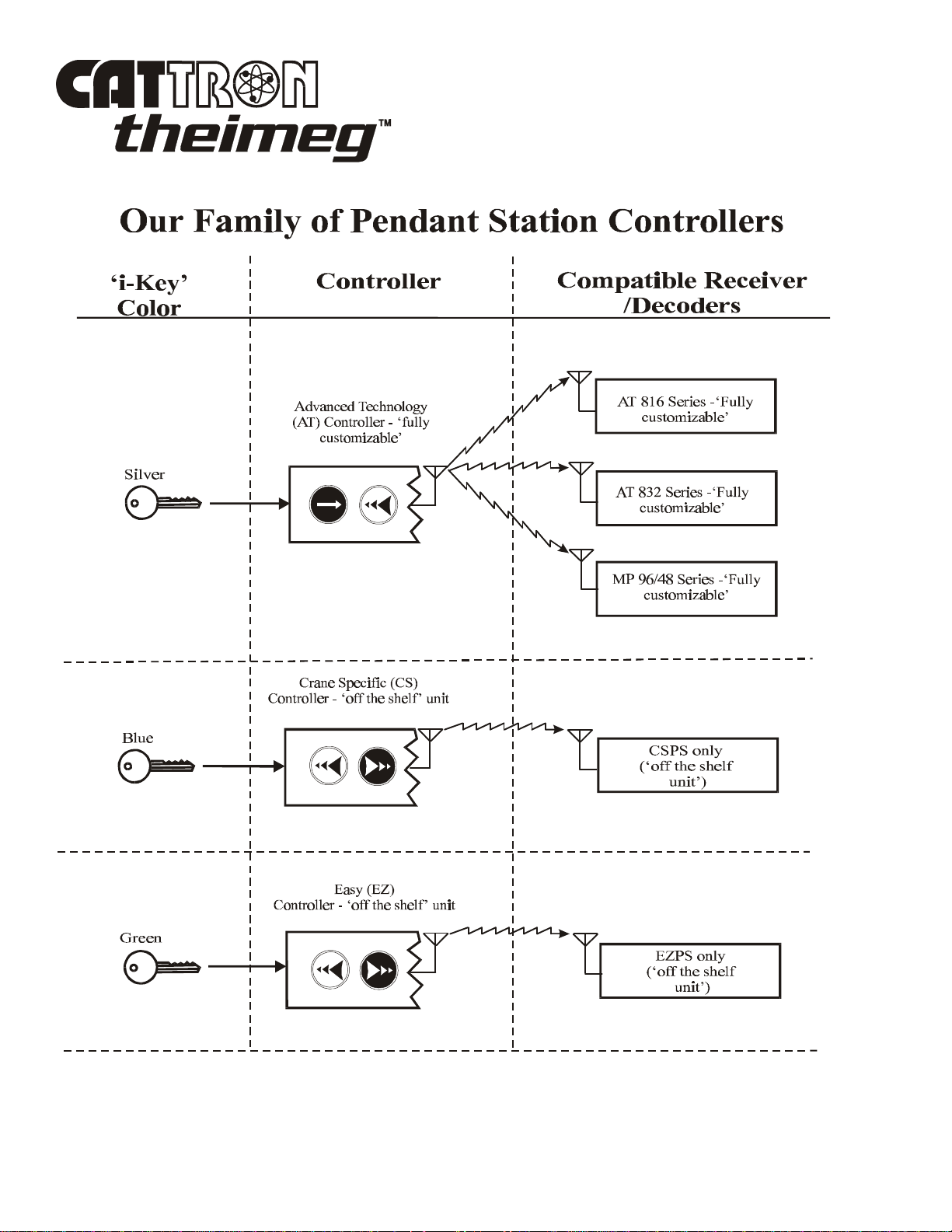
(PRC) System. CATTRON-THEIMEG™ PS controllers are offered in three family configurations:
PSEZ (Easy), PSCS (Crane Specific) and PSAT (Advanced Technology).
In all three CATTRON-THEIMEG™ families of PS controllers, operational security is advanced to its
maximum by the use of a removable stainless steel, electronic ‘i-Key’ which, when installed in the
controller, defines and enables the appropriate operating parameters. When the ‘i-Key’ is removed, the
controller is totally disabled. It should be noted that each family of PS controller has a specific colored
‘i-Key’ (green = EZ, blue = CS, and silver = AT) and that these ‘i-Keys’ are not interchangeable
between controller families.
The switch unit and electronics are contained in an extreme duty, water and dust resistant, aluminum
housing which has armorized rubber end-caps for switch protection and high impact resistance. The
controller housing is ergonomically designed with curved bottom and rubber side grips to allow
comfortable handling. The ‘i-Key’ is mounted in a receptacle located within the confines of the
armorized rubber ‘bumper’ that forms the top end-cap. Separate Power ON/OFF and STOP (red)
switches are also located next to the removable ‘i-Key’. The controller front face contains up to six
large pushbuttons that are engraved with their respective control function symbols. When pressed, each
pushbutton activates circuitry inside the controller. Pushbuttons may be of three-step or proportional
(stepless) operation.
Three-step pushbuttons provide 3-speed operation with a single pushbutton. When pressed, each
pushbutton step has a distinct limit of travel that provides an enhanced tactile feel that is noticed by the
operator.
Proportional (stepless) pushbuttons provide variable frequency drive (VFD) operation with a single
pushbutton. In these applications, the drive motor speed is directly proportional to the amount of travel
of the pushbutton (more distance = more speed).
Additional maintained and momentary depression toggle switches are mounted within a recessed
channel alongside the large control function pushbuttons. Note that PSAT models may be provided
with variety of custom switches
All commands from CATTRON-THEIMEG™ PS controllers respond within milliseconds of pressing or
releasing a pushbutton. Additionally, a mainline ON command is sent when power is turned on and resent anytime a controller function pushbutton is pressed. Within the PS controller, a microprocessor
performs self–diagnostics, interprets pushbutton and switch commands, and controls the radio
transmitter.
TM
01/2001, CATTRON - THEIMEG
Section 1, Page 1

Functional Description, continued.
CATTRON-THEIMEG™ PS controllers are equipped with an internal antenna and the typical operating
(transmitter) range is in excess of 500 feet (160+ meters). It should be understood that operating range
varies with environmental conditions. Should the transmitter go out of operating range, all motions will
cease.
CATTRON-THEIMEG™ PSAT series controllers have been approved to comply with both FCC Part 15
(non-continuous transmission) and FCC Part 90 (continuous transmission) applications, and for DOC
RSS-210 (non-continuous transmission) and RSS-119 (continuous transmission) applications standards.
No United States of America FCC, or Canadian DOC license is required for operation of FCC Part 15 or
RSS-210 (non-continuous transmission) PS controllers. Non-licensed PS controllers transmit the very
secure CATTRON-THEIMEG™ Series digital message, using frequency modulation (FM) radio. These
radio transmitters are approved for use on frequencies between 425-447MHz (M) and 447-473MHz (H).
They can be used on any frequency within these bands, including normally licensed channels without
the need for a license.
An authorized station operating license is required for the operation of US Part 90 and Canadian RSS119 (continuous transmission) applications. If you need assistance in obtaining these licenses, please
contact CATTRON-THEIMEG™ Inside Sales Department in the first instance.
As previously mentioned, operational security is maximized by the need to use a stainless steel
electronic ‘i-Key’ for controller operation. However, there is an additional and very significant
operational advantage of the CATTRON-THEIMEG™ ‘i-Key’ concept. It is that individual system
address, operating frequency and keypad configuration may be permanently stored in the ‘i-Key’,
depending on the type of controller supplied. Therefore, CATTRON-THEIMEG™ PS controllers
belonging to the same family at a user location can be identical - only the ‘i-Keys’ are different. To
simplify, each ‘i-Key’ is color-coded and labeled for an individual control system family, thus, any
CATTRON-THEIMEG™ PS controller will run any CATTRON-THEIMEG™ receiver/decoder
belonging to the same family as long as the correct ‘i-Key’ is used. As the result, this unique operating
concept reduces the need for specific spare remote controllers. Our unique family of PS controllers is
identified on the next page.
All CATTRON-THEIMEG™ PS controllers are powered by disposable 3-Volt alkaline or re-chargeable
Ni-Cad battery packs. In normal operation, a green LED ‘flashes’ with each function command message
and a ‘beep’ is sounded when a pushbutton is depressed. When the battery voltage becomes low, a
separate yellow LED flashes, alerting the operator that the battery pack needs to be replaced or recharged soon. Battery packs are easily and quickly replaced without the need for tools by turning two
knurled thumbscrews and removing the battery cover-plate located within the confines of the armorized
rubber bottom end-cap. The battery pack makes positive contact without snaps or plugs and has no
wires to break; simply drop it in, and replace the battery cover-plate.
Section 1, Page 2 01/2001, CATTRON - THEIMEG
TM

Functional Description, continued.
Ni-Cad battery packs can be re-charged ‘in-situ’ and do not need to be removed from the controller
housing. To enable such battery charging to be carried out, a series of optional battery chargers are
available for all CATTRON-THEIMEG™ PS controllers. One end of the charger is connected to the
mains power outlet, the other plugs into a covered socket located within the bottom end cap. Additional
options include an ‘AAA’ size battery adapter, and an external battery-charging unit – refer to
accessories/consumable items in Section 6 for details and part numbers.
A shoulder-carrying strap is standard for all CATTRON-THEIMEG™ PS controllers. This is quickly
and simply installed to a pair of ‘D’-rings located on the side of the controller.
Specifications.
Case Material:
Extreme duty, dust and water resistant, aluminum housing.
Approximate weight:
2.3lbs. / 1.04 Kg (including battery pack)
Dimensions:
12.0" x 3.0" x 2.0" (30.0cm x 7.6cm x 5.1cm).
Environmental:
Consult CATTRON-THEIMEG™ factory for a wide range of environmental solutions.
Maximum Functions:
Up to 20 operator commands, depending on controller configuration.
Operator Control Functions – PSAT Series:
Up to six large pushbuttons (proportional type, three-step type, or any combination of
these two), plus additional toggle switches and/or pushbuttons, as required.
01/2001, CATTRON - THEIMEG
TM
Section 1, Page 3

Specifications, continued.
Operator Control Functions – PSEZ & PSCS:
Six large pushbuttons (three-step type only), plus two auxiliary function switches and a
selector for motors A or B, or both A+B.
Battery type:
3-Volt Alkaline Battery Pack (standard).
2.4 Volt re-chargeable Ni-Cad Battery Pack (optional).
3-Volt Alkaline Battery Adapter for use with quantity 2 ‘AAA’ size Alkaline
batteries only (optional).
Battery life (20% Duty Cycle):
3 Volt alkaline battery pack (standard) or re-chargeable Ni-Cad battery pack
(optional). In USA, Canada and non EU countries, battery life is:- Ni-Cad pack
– 50 hours, Alkaline pack – 115 hours, ‘AAA’ Alkaline batteries (using
optional adapter) – 50 hours. In EU countries, battery life is:- Ni-Cad pack – 30
hours, Alkaline pack – 65 hours, ‘AAA’ Alkaline batteries (using optional
adapter) – 25 hours.
Transmit indicator:
Green LED flashes with every transmission.
Low battery indication:
Yellow LED flashes for low battery, low battery alert signal beeps every 10 seconds.
Battery charging:
Internal Ni-Cad battery charging. Optional ‘Standard’ rate (10 hour) or ‘Rapid’
rate (1-hour) Battery Chargers are available for use in countries having 110-120
VAC mains input power. Alternatively, optional ‘Rapid’ or ‘Trickle’ Battery
chargers are available for use in countries having 220-240 VAC mains input
power. An External Battery Charging Unit is also available for use with all
optional CATTRON-THEIMEG™ battery chargers.
Audio speaker:
For function pushbutton ‘click’ and low battery indication.
Transmitter frequency:
425-447MHz (M) or 447-473MHz (H).
Section 1, Page 4 01/2001, CATTRON - THEIMEG
TM
Overview – CATTRON-THEIMEG™ Remote Control Systems.
12 VDC
DIRECTIONAL OUTPUT RELAYS
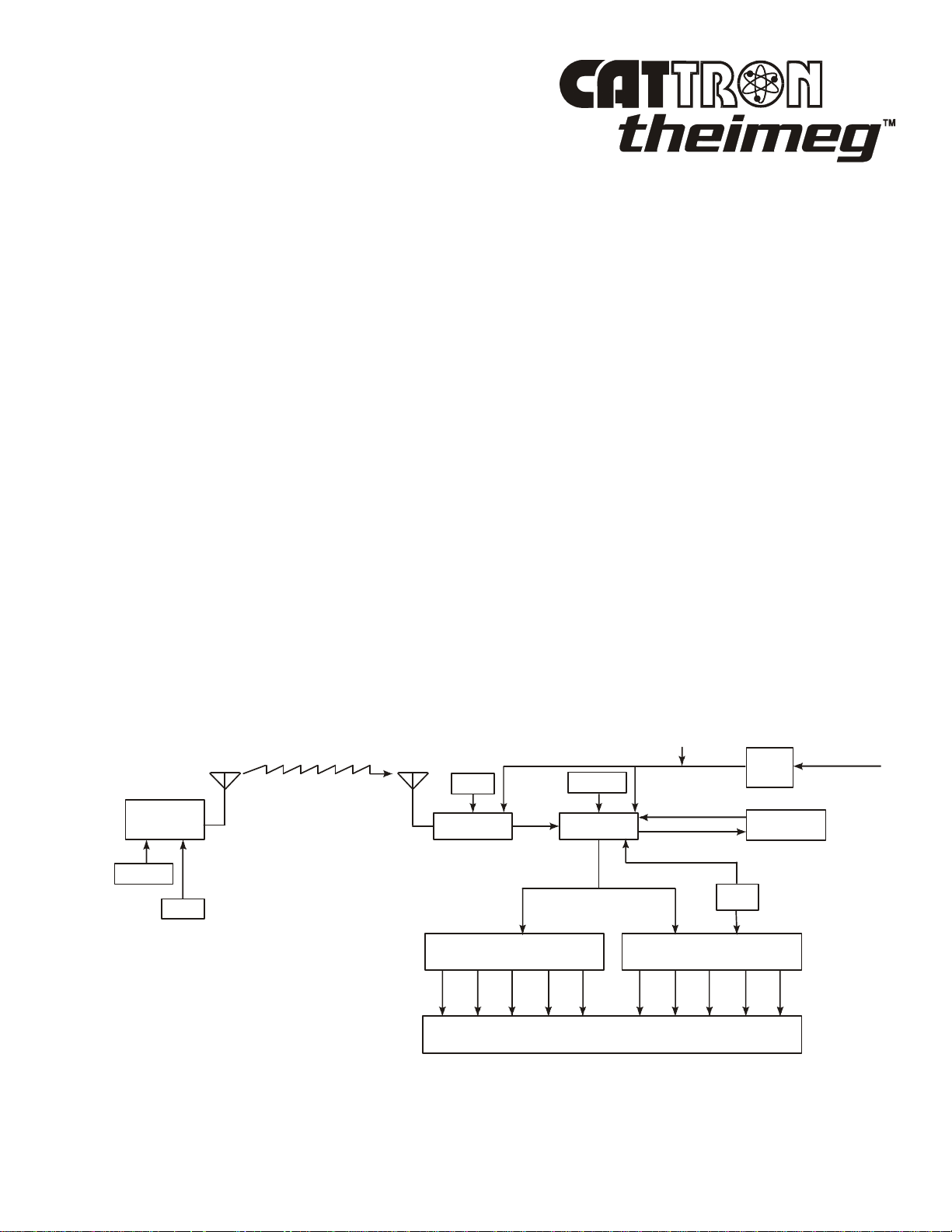
Figure 1-1 below shows a simplified block diagram of a typical CATTRON-THEIMEG™ remote control
system. Refer to this figure and the following paragraphs for a functional description of the remote
control system.
The target receiver/decoder is controlled by the Pendant Station Controller. Provided the correct
coded ‘i-Key’ is inserted into the controller, the controller sends signals to the receiver/decoder using an
UHF radio link. The signal is picked up by the antenna and passed on to the receiver. If the signal is the
correct frequency and passes all required data tests, the signal is passed on to the decoder. The decoder
compares the address code of the signal to its own address code. If the signal’s address code does not
match its address code, it is ignored and a message is displayed on a system status display located in the
receiver/decoder unit. If the address code is correct, the decoder processes the message and energizes
and de-energizes the appropriate control, directional output, three-speed and auxiliary function relays
located within the control system.
An Automatic Safety Override (ASO) function continually monitors the state of all directional relay
outputs (i.e. Forward/Reverse). If a directional relay electrically fails closed without a command from
the controller, the ASO circuit logic de-energizes the master output relay (OPR).
During operation, the microprocessor on the decoder board resets multiple watchdog timer circuits
whenever valid messages are received and decoded. If the microprocessor fails to reset the watchdog
timers, the timer circuits shut down and de-activate all relay outputs. The decoder microprocessor
requires continuously valid transmitted signals to be received and decoded or all relay output functions
will be de-activated unless programmed otherwise. It should be noted that the mainline control relay
(OPR) would be maintained for up to 10 minutes, depending on system configuration.
Figure 1-1. Typical Radio Remote Control System, simplified block diagram
Tx
PENDANT
CONTROLLER
ADDRESS
FREQ
Rx
TM
01/2001, CATTRON - THEIMEG
POWER
FREQ
RECEIVER DECODER
THREE-SPEED AND AUXILIARY
FUNCTION OUTPUT RELAYS
ADDRESS
MACHINE WIRING
SUPPLY
WATCHDOG
TIMER
ASO
END OF SECTION
Section 1, Page 5
115 VAC
50-60 HZ

This page intentionally left blank
Section 1, Page 6 01/2001, CATTRON - THEIMEG
TM

Section 2 – Safety Information
Safety Considerations.
CATTRON-THEIMEG™ believes that to safely operate any remotely controlled equipment, the overall
system needs to be configured so that movement or operation of the equipment will take place only
when the device is commanded to move or operate. For example; overhead cranes must be equipped
with a braking system, which can only be released when an electrical signal is sent to the motor.
Removal of electrical power or loss of the radio transmitted signal results in application of the brakes.
One way to accomplish this is with a CATTRON-THEIMEG™ Electro-Hydraulic brake package –
contact the factory for details.
In keeping with this philosophy - NO COMMAND, NO MOVEMENT - CATTRON-THEIMEG™ has
designed your radio remote control system with the following safety and security features.
‘i-Key’: Operational security is advanced to its maximum by the use of a removable
stainless steel, electronic, ‘i-Key’ which, when installed to the Pendant controller, defines
and enables the operating parameters. When the ‘i-Key’ is removed, the controller is totally
disabled.
Unique address code: Each PS series controller and receiver/decoder pair is configured
with a unique address code so that the equipment will respond only to the controller whose
address code matches that of the decoder.
Intelligent digital message protocol: CATTRON-THEIMEG™ remote control systems
utilize a unique message protocol for industrial control applications rather than the
customary Electronic Data Processing (EDP) type of message format.
ON/OFF power switch: The PS controller is provided with a rotary power ON/OFF switch
that must be set to ‘ON’ in order to send commands to the receiver/decoder. If the power
switch is set to ‘OFF’, the decoder will remove all commands from the controlled
machinery, stopping all movement. However, the mainline control relay (OPR) will be
maintained for up to 10 minutes, depending upon system configuration.
Red System STOP Switch: Operating the red STOP switch while the PS controller is
turned on will repeatedly send a burst of stop commands to all outputs including the
mainline control relay (OPR).
Operate relay (OPR): The operate (OPR) output relay shall be wired to control a userprovided electro-magnetic power contactor. The electro-magnetic contactor opens and
closes the main electrical supply circuit(s) to the controlled device.
Data Error Checking: All communications from the Pendant controller to the
receiver/decoder contain error-checking information (BCH data error detection routines).
The entire data command packet must pass error detection tests before being processed.
01/2001, CATTRON - THEIMEG
TM
Section 2, Page 1
LL1
LL2
LL3
MOTOR
EXISTING CONTROLS
Typical method of operation (incorporating above safety features) using a radio controlled overhead
crane as an example:
The Operate (OPR) relay(s) is energized for the first time when:
The red STOP and rotary ON/OFF switches on the PS Controller are operated in the
proper sequence (first unlatch and pull up STOP switch to ‘RUN’, then rotate ON/OFF
switch to ‘ON’), the correct coded ‘i-Key’ is installed, and the target receiver/decoder
has power applied. With all these conditions satisfied, a matching address code is sent by
way of RF signal from the PS controller to the decoder.
The OPR relay is wired to the mainline (ML) contactor on the crane. Once the mainline is energized, a
continuously repeated valid signal must be received for function outputs to engage. If this signal is
interrupted for any reason, all function outputs will turn off unless programmed otherwise.
When operating within the USA, FCC rules state that RF transmitters in non-licensed controllers must
switch off within five seconds after the operator releases a function pushbutton. Consequently, the OPR
output is programmed to stay on for up to ten minutes after the last valid message is received. During
this time all Automatic Safety Override (ASO) monitored outputs must stay off or the ASO sensing in
the decoder will interrupt this hold up time, de-energizing OPR.
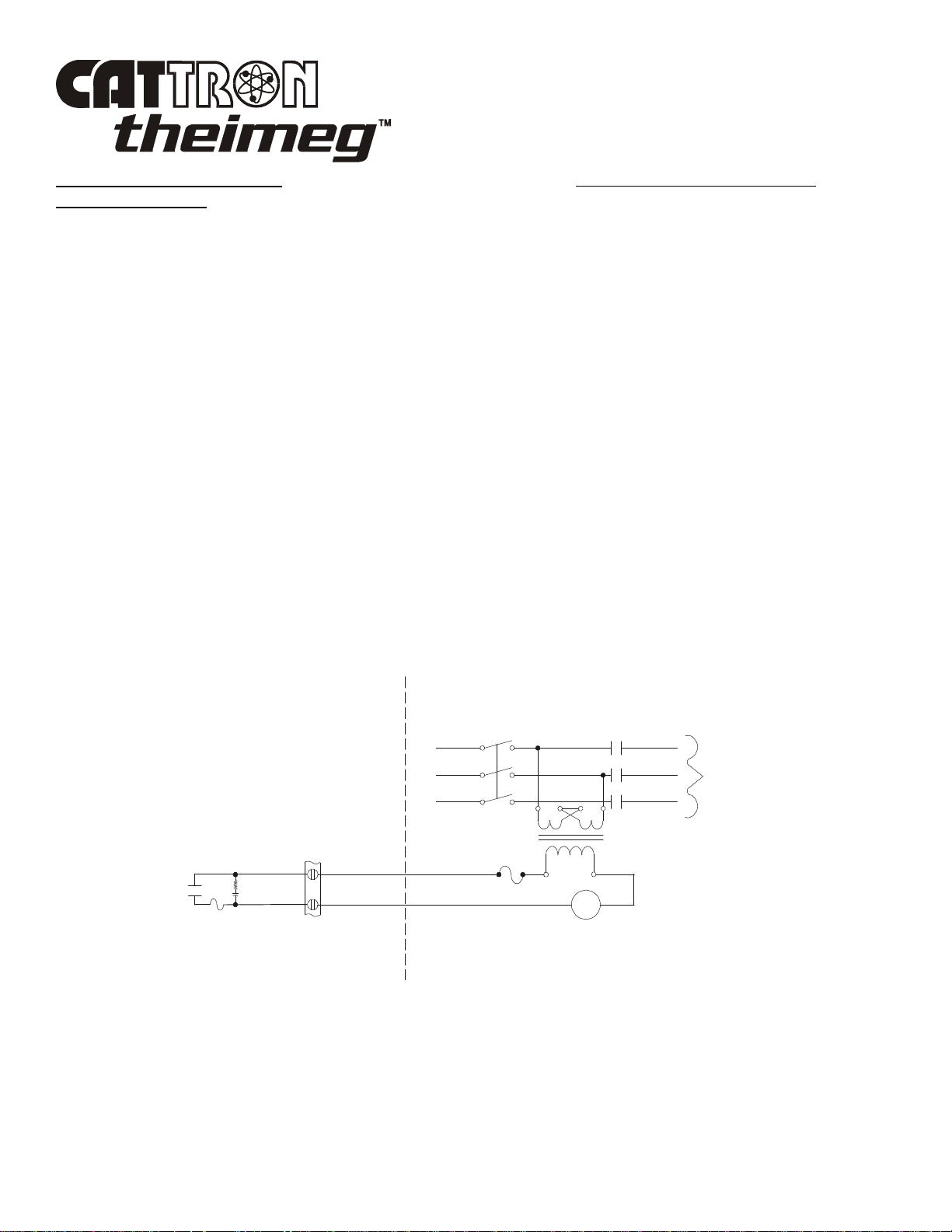
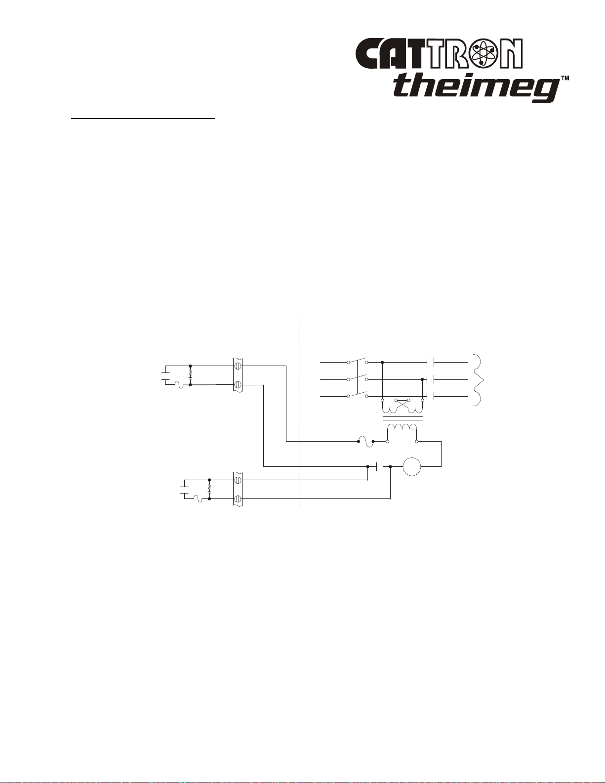
Figure 2-1 below shows an Operate (OPR) contact wired directly to the mainline (ML) contactor.
Provided the red STOP switch on the Pendant Controller is pulled out and the correct coded ‘i-Key’ is
installed, setting the green ON/OFF power switch on the Pendant controller to ‘ON’ will energize the
mainline contactor.
Figure 2-1. Operate (OPR) contact wiring
MANUAL
DISCONNECT
ML
L1
L2
TO
L3
OPR
5.0A
R
C
120V
ML
RECEIVER/DECODER
An auxiliary function may be used as a Reset (RST) output that will only be effective when the Operate
(OPR) relay has been closed. Momentary closure of the Reset (RST) relay picks up the mainline (ML)
contactor, which is maintained under control of the OPR. Thus, power is supplied to the controlled
device. If OPR opens, the mainline contactor releases, removing power from the controlled device and
stopping all motion.
Section 2, Page 2 01/2001, CATTRON - THEIMEG
TM
Typical method of operation, continued.
120V
MANUAL
DISCONNECT
LL1
LL2
LL3
MOTOR
RECEIVER/DECODER
EXISTING CONTROLS
Figure 2-2 below shows the Operate (OPR) relay and optional Reset (RST) relay wired to control a
mainline contactor. This configuration requires the operator to activate the reset function on the
controller after he/she has turned the unit on. Once reset, the ML contactor stays energized until OPR
de-energizes.
In addition to being energized by the presence of a signal from the controller, OPR is under supervision
of the Automatic Safety Override (ASO) circuit. The ASO circuit disables the OPR (shutting down the
controlled machinery) if a directional output relay is active when no corresponding command is being
received from the controller. In this event, no action is required by the operator to stop the equipment.
The ASO safety circuitry will stop motion automatically without any operator command when a
directional output relay fault is detected.
Figure 2-2. Operate (OPR) contactor and Reset Relay (RST) wiring
OPR
RST
R
C
5.0A
R
C
5.0A
L1
L2
L3
ML
TO
ML
ML
TM
01/2001, CATTRON - THEIMEG
Section 2, Page 3
Radio Control Operator’s Duties – General Equipment.
WARNINGS:
ALL EQUIPMENT MUST HAVE A MAINLINE (ML) CONTACTOR
INSTALLED AND ALL TRACKED EQUIPMENT (i.e. CRANES) HAVE A
BRAKE INSTALLED.
THE REMOTE CONTROL OPERATE (OPR) RELAY MUST BE
CONNECTED TO THE MAINLINE SO THAT STOP COMMANDS OR
FAULT CONDITIONS MONITORED BY AUTOMATIC SAFETY
OVERRIDE (ASO) CIRCUITRY WILL DE-ENERGIZE THE MAINLINE
CONTACTOR AND SET THE EQUIPMENT BRAKE.
FAILURE TO COMPLY WITH THE ABOVE WARNINGS MAY RESULT IN
SERIOUS INJURY OR DEATH TO PERSONNEL AND DAMAGE TO
EQUIPMENT.
WARNINGS:
MORE THAN ONE REMOTE CONTROL SYSTEM MAY BE USED AT,
AROUND, OR NEARBY YOUR OPERATING FACILITY. THEREFORE,
BEFORE INSERTING AN ‘i-Key’ INTO A PS CONTROLLER, YOU MUST
INSURE THE CORRECT CODED ‘i-Key’ IS SELECTED FOR THE
DESIRED EQUIPMENT TO BE OPERATED.
IF THE WRONG ‘i-Key’ IS INSERTED INTO A PSAT SERIES
CONTROLLER, OR IF THE WRONG ADDRESS AND FREQUENCY IS
PROGRAMMED INTO A PSEZ OR PSCS SERIES CONTROLLER, OTHER
EQUIPMENT LOCATED AT, AROUND, OR NEARBY YOUR FACILITY
MAY BECOME OPERATIONAL.
FAILURE TO COMPLY WITH THE ABOVE WARNINGS MAY RESULT IN
OPERATION OF UNDESIRED EQUIPMENT WHICH IN TURN COULD
RESULT IN SERIOUS INJURY OR DEATH TO PERSONNEL AND
DAMAGE TO EQUIPMENT.
WARNING:
ON CAB AND REMOTE OPERATED CRANES OR CARRIERS AN
AUDIBLE OR VISUAL WARNING MEANS SHALL BE PROVIDED. IN
ADDITION, ALL EQUIPMENT SHALL HAVE AUDIO OR VISUAL ALARM
INDICATIONS MEETING GOVERNMENTAL REQUIREMENTS. FAILURE
TO IMPLEMENT THIS WARNING MAY RESULT IN PERSONAL INJURY
OR DEATH TO PERSONNEL AND DAMAGE TO EQUIPMENT.
Section 2, Page 4 01/2001, CATTRON - THEIMEG
TM

Radio Control Operator’s Duties – General Equipment, continued.
WARNING:
CATTRON-THEIMEG™ PSEZ AND PSCS PORTABLE REMOTE
CONTROL (PRC) SYSTEMS ARE NOT DESIGNED TO INTERFACE
DIRECTLY TO SAFETY CRITICAL BI-STABLE MAINTAINED
FUNCTIONS (i.e., electro-magnet circuits, vacuum circuits, grab, pump motors,
fire suppression etc.).
CONTACT CATTRON-THEIMEG™ FACTORY FOR INFORMATION
REGARDING PROPER INTERFACE TO SAFETY CRITICAL BI-STABLE
MAINTAINED FUNCTIONS.
SHOULD CATTRON-THEIMEG™ PSCS AND PSEZ PORTABLE REMOTE
CONTROL SYSTEMS BE INADVERTENTLY CONFIGURED TO
INTERFACE DIRECTLY WITH SAFETY CRITICAL BI-STABLE
MAINTAINED FUNCTIONS AT YOUR OPERATING FACILITY, DAMAGE
TO EQUIPMENT, SERIOUS INJURY, OR DEATH TO PERSONNEL MAY
RESULT.
IT MUST BE FULLY UNDERSTOOD THAT CATTRON-THEIMEG™ WILL
NOT BE HELD LIABLE FOR PERSONAL INJURY, DEATH, EQUIPMENT
OR PROPERTY DAMAGE WHICH MAY ARISE FROM IMPROPER
CONFIGURATION OF YOUR PORTABLE REMOTE CONTROL SYSTEM.
The following procedures provide general guidelines for radio control operation of equipment and
should not be used as a substitute for your plant operating procedures.
1. Before operating equipment, carry out the following:
a. Install the correct coded ‘i-Key’ for the target equipment to be operated. If the wrong
coded ‘i-Key’ is installed to the PS controller, the target equipment will not operate.
However; other equipment located at, around, or nearby your facility may become
operational.
b. Set (unlatch and pull out) PS controller red STOP switch to ‘RUN’ and turn Power
ON/OFF switch to ‘ON’. When transmitting with a good battery, two short ‘beeps’ will
be heard immediately after the ON/OFF power switch is set to ‘ON’ and the green
TRANSMIT LED will ‘flash’ rhythmically. When the battery starts to go low, the
yellow LOW BATTERY LED will ‘flash’ continuously, which means you should change
or re-charge the battery pack (refer to Battery Pack in Section 4 of this manual for
instructions on how to replace a battery pack).
01/2001, CATTRON - THEIMEG
TM
Section 2, Page 5

Radio Control Operator’s Duties – General Equipment, continued.
c. When installed, activate the ALARM/RESET switch on the PS controller (this is
normally an optional function that sounds the equipment alarm and resets the main power
contactor).
d. Check each function independently to be sure that equipment is responding correctly.
e. Where a limit switch is provided, you should check the limit switch at the beginning of
each shift as defined by your plant operating procedures.
f. Check Range Limiting if used.
g. Check STOP operation
h. Check brake operation.
2. You must report all defective or missing safety equipment, mechanical or electrical defects to
your supervisor without delay. Do not continue operation until fully repaired.
3. If anyone is in the path of equipment travel, stop and sound the alarm before proceeding.
4. Persons operating this equipment shall not use a limit stop as a utility stopping device.
5 When leaving the equipment area for any reason, set (push down) the PS controller red STOP
switch to ‘STOP’ and turn power ON/OFF switch to ‘OFF’. Remove the ‘i-Key’ from the PS
controller and keep it on your person.
6. Do not allow any unauthorized person to operate the PS controller.
7. Do not operate the PS controller at a distance where the equipment and all surrounding objects
are not visible.
8. Do not attempt to override any of the safety features built into the Radio Control System.
9. If for any reason you or anyone has to board the radio-controlled equipment, set (push down) the
Pendant controller red STOP switch to ‘STOP’ and turn the power ON/OFF switch to ‘OFF’.
Remove the ‘i-Key’ from the PS controller and keep it on your person.
Section 2, Page 6 01/2001, CATTRON - THEIMEG
TM
Radio Control Operator’s Duties – E.O.T. Crane.
WARNINGS:
ALL EQUIPMENT MUST HAVE A MAINLINE (ML) CONTACTOR
INSTALLED AND ALL TRACKED EQUIPMENT (i.e. CRANES) HAVE A
BRAKE INSTALLED.
THE REMOTE CONTROL OPERATE (OPR) RELAY MUST BE
CONNECTED TO THE MAINLINE SO THAT STOP COMMANDS OR
FAULT CONDITIONS MONITORED BY AUTOMATIC SAFETY
OVERRIDE (ASO) CIRCUITRY WILL DE-ENERGIZE THE MAINLINE
CONTACTOR AND SET THE EQUIPMENT BRAKE.
FAILURE TO COMPLY WITH THE ABOVE WARNINGS MAY RESULT IN
SERIOUS INJURY OR DEATH TO PERSONNEL AND DAMAGE TO
EQUIPMENT.
WARNING:
DUE TO FCC PART 15 AND DOC RSS-210 RADIO TRANSMIT
REGULATIONS, THE OPR OUTPUT TO WHICH YOUR CONTROLLED
EQUIPMENT’S MAINLINE CONTACTOR IS CONNECTED WILL
REMAIN ENERGIZED FOR TEN MINUTES AFTER THE CONTROLLER
POWER IS SET TO ‘OFF’, OR FOR TEN MINUTES AFTER THE LAST
TIME A PUSHBUTTON IS DEPRESSED. CONSEQUENTLY, SPECIAL
CARE MUST BE TAKEN IF THE CRANE OR TRACKED MACHINE IS
EQUIPPED WITH A PARKING BRAKE THAT IS CONFIGURED TO
ENGAGE WHEN THE MAINLINE CONTACTOR DE-ENERGIZES.
TO PREVENT A POTENTIALLY HAZARDOUS SITUATION, YOU
SHOULD IMMEDIATELY PRESS THE RED ‘STOP’ BUTTON ON YOUR
REMOTE CONTROLLER AFTER COMPLETION OF CRANE
OPERATIONS. SUCH ACTION WILL INSURE THE PARKING BRAKE
(IF EQUIPPED AND CONFIGURED AS ABOVE) IS SET, PREVENTING
UNINTENTIONAL MOVEMENT OF THE CRANE OR TRACKED
MACHINE.
FAILURE TO COMPLY WITH THIS WARNING MAY RESULT IN
SERIOUS INJURY OR DEATH TO PERSONNEL AND DAMAGE TO
EQUIPMENT.
01/2001, CATTRON - THEIMEG
TM
Section 2, Page 7
 Loading...