

Cattron North America MKU915A Users Manual

1. Insert the correct ‘TransKey’. This coded electronic key sets the unique operating
parameters for a given control system. These parameters include, address code,
operating frequency and function key (pushbutton) configurations. Note that an OCU
will not operate without a ‘TransKey’ installed.
NOTE: If your controller uses the bottom row of keypad switches for ‘ON’,
‘OFF’, and ‘STOP’ functions, proceed directly to step 5 of this
procedure.
2. Set red STOP Switch to ‘RUN’. Pulling this switch upward enables power to be
applied to the OCU. If the switch has been pushed down to the ‘STOP’ position, you
will first have to unlatch the switch knob by rotating in a clockwise direction.
3. Set ON/OFF Switch to ‘ON’. Rotating this switch clockwise applies power to the
OCU. If the multicolor STATUS LED illuminates green and two short beeps are
heard, the OCU is ready for use and a power up message has been sent to the
target MCU. The targeted MCU will respond by energizing the mainline contactor of
your controlled machine.
WARNING:
BEFORE ATTEMPTING TO USE THE REMOTE CONTROL SYSTEM, VERIFY THE
TARGET CRANE OR MACHINE YOU WISH TO OPERATE IS UNDER THE DIRECT
COMMAND OF YOUR OCU. THIS IS ACCOMPLISHED BY OPERATING A NONMOTION OCU FUNCTION SUCH AS A HORN OR LAMP AND OBSERVING THAT
THE RESPECTIVE FUNCTION ON THE TARGETED CRANE OR MACHINE
RESPONDS.
FAILURE TO IMPLEMENT THE ABOVE MAY RESULT IN PERSONAL INJURY OR
DEATH TO PERSONNEL AND DAMAGE TO EQUIPMENT.
4. Press a non-motion Function Key (pushbutton) such as a horn or lamp and
observe that the targeted crane or machine responds. The OCU is now fully
operational and transmitting a signal as indicated by the green ‘TRANSMIT’ LED
flashing. Operate the keypad control and auxiliary pushbuttons as required,
remembering that each pushbutton must be maintained in order for the function to
continue to operate. Any or all functions may be operated simultaneously if the
controlled machine permits such operation.
Page 34 Part # 68C-MKU, Edition 01/2007, Version 1.0
NOTES: A system STOP may be initiated at any time during the control function
by pushing the red STOP switch downwards. It should be further
noted that in “pitch and catch” control operations where two OCUs are
used, only the OCU that sets the ‘STOP’ condition will re-set the ‘RUN’
condition.
When all control functions have been completed, we recommend you
initiate a system STOP (push red STOP switch down) before setting the
ON/OFF switch to the ‘OFF’ position.
5. Alternative Power-up procedure using bottom row keypad sw itches :
Referring to Figure 15 overleaf
:
a. Press the ‘ON’ keypad pushbutton once and observe the multicolor STATUS
LED illuminates red.
b. Press the ‘STOP’ keypad pushbutton once (1st & 2nd step) and observe the
multicolor STATUS LED illuminates orange.
c. Press the ‘ON’ keypad pushbutton once again and observe the multicolor
STATUS LED illuminates green..
NOTE: The above Power-up sequence must be completed within 10 seconds.
WARNING:
BEFORE ATTEMPTING TO USE THE REMOTE CONTROL SYSTEM, VERIFY THE
TARGET CRANE OR MACHINE YOU WISH TO OPERATE IS UNDER THE DIRECT
COMMAND OF YOUR OCU. THIS IS ACCOMPLISHED BY OPERATING A NONMOTION OCU FUNCTION SUCH AS A HORN OR LAMP AND OBSERVING THAT
THE RESPECTIVE FUNCTION ON THE TARGETED CRANE OR MACHINE
RESPONDS.
FAILURE TO IMPLEMENT THE ABOVE MAY RESULT IN PERSONAL INJURY OR
DEATH TO PERSONNEL AND DAMAGE TO EQUIPMENT.
6. Press a non-motion Function Key (pushbutton) such as a horn or lamp and
observe that the targeted crane or machine responds. The MKU controller is now
fully operational and transmitting a signal as indicated by the multicolor STATUS
LED flashing green. Operate the keypad control and auxiliary pushbuttons as
required, remembering that each pushbutton must be maintained in order for the
function to continue to operate. Any or all functions may be operated simultaneously
if the controlled machine permits such operation.
Part # 68C-MKU, Edition 01/2007, Version 1.0 Page 35
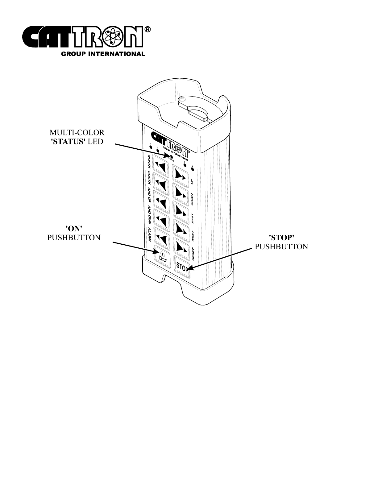
Figure 15. Alternative MKU Controller - Power-up using bottom row keypad switches
Page 36 Part # 68C-MKU, Edition 01/2007, Version 1.0
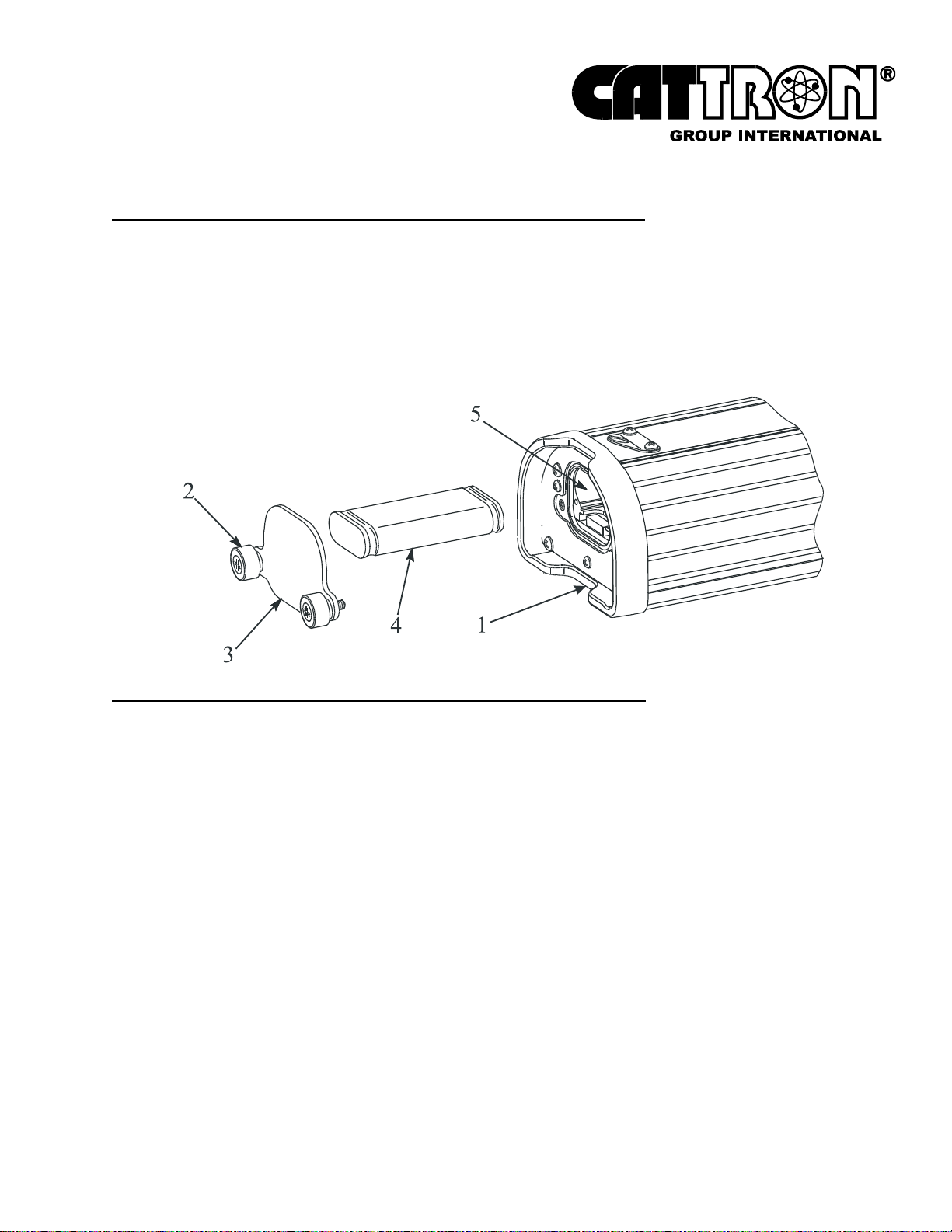
6.4 CHANGING THE BATTERY PACK
Referring to Figure 16 below, remove the battery pack as follows:
a. Lay MKU controller (1) face down.
b. Release two knurled thumbscrews (2) and withdraw cover-plate (3).
c. Withdraw battery pack (4) from battery compartment (5).
Figure 16. Battery Pack, removal and replacement
Referring to Figure 16 above, replace the battery pack as follows:
a. Position battery pack (4) with the four contact strips facing down and forwards.
Install battery pack (4) by pushing fully home inside the battery compartment (5).
b. Install cover-plate (3) and secure by evenly hand tightening two knurled
thumbscrews (2). Do not overtighten - a snug fit is all that is necessary.
Part # 68C-MKU, Edition 01/2007, Version 1.0 Page 37
6.5 CHARGING THE BATTERY PACK
NOTES: Do not re-charge the battery pack until the OCU’s LED indicates
‘low battery’.
A CATTRON® External Battery Charging Unit (Part # 70C-0003) will
be required for battery charging or conditioning.
A CATTRON® ‘Standard’ Battery Charger (Part # 70C-0001) enables a Ni-Cad battery pack
to be charged within a period of 10 hours from a 110-120 VAC mains supply. Standard rate
chargers include a yellow LED to indicate charge mode.
A CATTRON® ‘state of the art’ Battery Conditioner (Part # 70C-0002) is also available for use
with Ni-Cad battery packs only. For details, refer to Battery Pack Conditioning, below.
CAUTIONS:
CATTRON® MKU Battery Conditioners and External Charging Units are designed
for use with CATTRON® Ni-Cad Battery Packs only.
Battery Packs must be removed or disconnected from Battery Conditioners/
External Charging Units within 48-hours of achieving the fully charged state.
Failure to comply with these Cautions may result in equipment and/or battery
damage and will void our warranty.
Battery Pack Charging: To charge a Ni-Cad Battery Pack, refer to Figure 17 opposite and
connect the CATTRON® Battery Charger to the mains power supply. Install the charging jack
to the external battery charging unit socket. Simply drop the battery pack into the battery
charging unit, ensuring the battery pack contacts are positioned as shown. When the Ni-Cad
battery pack is properly installed, the appropriate charging indicator on the connected battery
charger will illuminate.
Page 38 Part # 68C-MKU, Edition 01/2007, Version 1.0
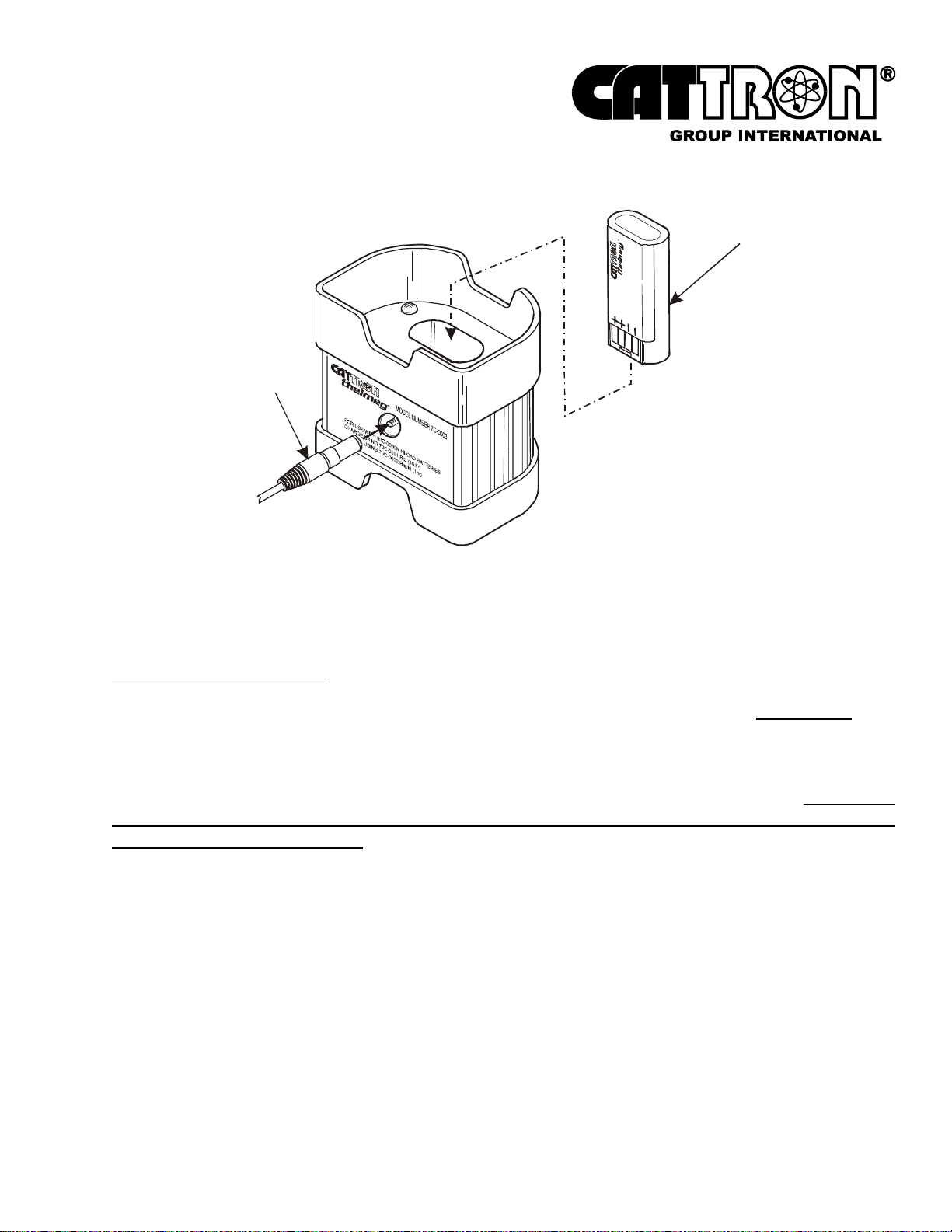
Figure 17. External Ni-Cad Battery Pack Charging
NI-CAD BATTERY PACK ONLY
P ART # 60C-0060N
CHARGING JACK
FROM BATTERY
CHARGER
6.6 CONDITIONING THE BATTERY PACK
A ‘state of the art’ CATTRON® Battery Conditioner (Part # 70C-0002) is available for use with
Ni-Cad battery packs only.
The Battery Conditioner automatically conditions the battery pack by first discharging it at
750mA for 1.5 hours before applying a rapid charge for 1.2 hours. The conditioner
incorporates end of charge detection circuitry to accurately sense when the battery pack is fully
charged. When this condition has been detected, the conditioner switches to a ‘trickle’ mode
that keeps the battery pack fully charged and ready to use for up to 48-hours. To prevent
damage to the battery pack, it should be removed from the conditioner within 48-hours of
achieving a fully charged state.
The CATTRON® Battery Conditioner incorporates an LED that indicates status as follows:
Amber Color – indicates the battery pack is being discharged.
Red Color - indicates the battery pack is being charged at a rapid rate.
Green Color - indicates the battery pack is fully charged and that a ‘trickle’ charge is
being applied to maintain the fully charged state. The battery pack is ready for use and
should be removed from the conditioner within 48-hours.
Part # 68C-MKU, Edition 01/2007, Version 1.0 Page 39

CAUTIONS:
CATTRON
®
MKU Battery Conditioners and External Charging Units are designed
for use with CATTRON® Ni-Cad Battery Packs only.
Battery Packs must be removed or disconnected from Battery Conditioners/
External Charging Units within 48-hours of achieving the fully charged state.
Failure to comply with these Cautions may result in equipment and/or battery
damage and will void our warranty.
The Battery Conditioner includes a Mains VAC Adaptor that enables the conditioner to operate
from mains supply voltages between 100 and 240 VAC @ 50/60 kHz. Referring to Figure 18
opposite, this adaptor is connected as shown. Similarly, when connecting the Battery
Conditioner to the External Battery Charging Unit, refer to Figure 18 for the appropriate
connections.
Page 40 Part # 68C-MKU, Edition 01/2007, Version 1.0
Figure 18. Battery Pack Conditioning – interconnection details
Part # 68C-MKU, Edition 01/2007, Version 1.0 Page 41
6.7 ALKALINE BATTERY ADAPTER
CAUTION:
CATTRON® MKU Battery Adapters are designed for use with non re-chargeable
‘AAA’ size Alkaline Batteries only. Carbon/Zinc, Lithium, or Ni-Cad Batteries are
not to be used with this adapter. Damage to batteries will occur if this adapter is
used for battery charging.
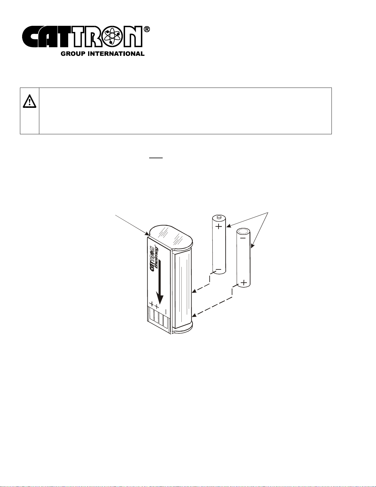
Referring to Figure 19 below, a CATTRON® Battery Adapter is available which will accept two
‘AAA’ size Alkaline 1.5-volt batteries only. It should be noted that when using ‘AAA’ size
Alkaline 1.5-volt batteries with this adapter, battery life will only be 40% of that provided by a
CATTRON® Alkaline Battery Pack.
Figure 19. ‘AAA’ Alkaline Battery Adapter
BATTERY ADAPTER, 3 VOLT
(QUANTITY 2 x ‘AAA’ SIZE)
USE ‘AAA’ ALKALINE
BA TTERIE S ONLY
Page 42 Part # 68C-MKU, Edition 01/2007, Version 1.0

7 MAINTENANCE INSTRUCTIONS
Unless customer technicians have received formal maintenance training from CATTRON®, our
maintenance philosophy is that inoperative OCUs and MCUs be returned as complete units to
our workshops for repair. This is because each system has been customized at our factory for
a particular application, thus it is highly unlikely that two control systems will be the same.
NOTE: When returning an OCU for repair, the original 'TransKey' supplied
with the unit should be removed and retained for use with your spare
unit.
7.1 PREVENTIVE MAINTENANCE
Preventive maintenance for MKU systems is minimal because they are extremely durable and
reliable units. Preventive maintenance is limited to the following:
Daily Visual Inspection:
Before use, visually inspect the OCU and MCU for cleanliness, physical damage, and
security of external parts (screws, switches, rubber grips, etc.). CATTRON® emphasizes
that regular visual inspections not only mean quickly locating a source of potential
problems, but also may prevent serious problems from developing later.
Cleaning the Transmitter:
The OCU should be cleaned with a moist cloth (if necessary, with a little washing-up liquid),
then wiped dry with a clean paper towel. DO NOT IMMERSE THE OCU IN WATER.
Functional Check:
A functional check is accomplished by operating the OCU in accordance with the Operating
Procedures in Para. 6.3 on page 32 of this manual. Insure all system control functions are
fully operational.
7.2 TRANSMITTER FAULT MESSAGES
The OCU has a multicolor STATUS LED indicator that displays the current system status to
the operator. When an OCU fault is detected, the multicolor STATUS LED will illuminate red
and signal this with a series of blinks. Refer to Table 2 overleaf for the blink sequence and the
corresponding fault messages.
Note that any repairs or replacements should only be made by CATTRON® trained
technicians.
Part # 68C-MKU, Edition 01/2007, Version 1.0 Page 43
 Loading...