

Cattron North America MK90 User Manual

R
Section 1
Section 2 – Product Data & Specifications
Functional Description.
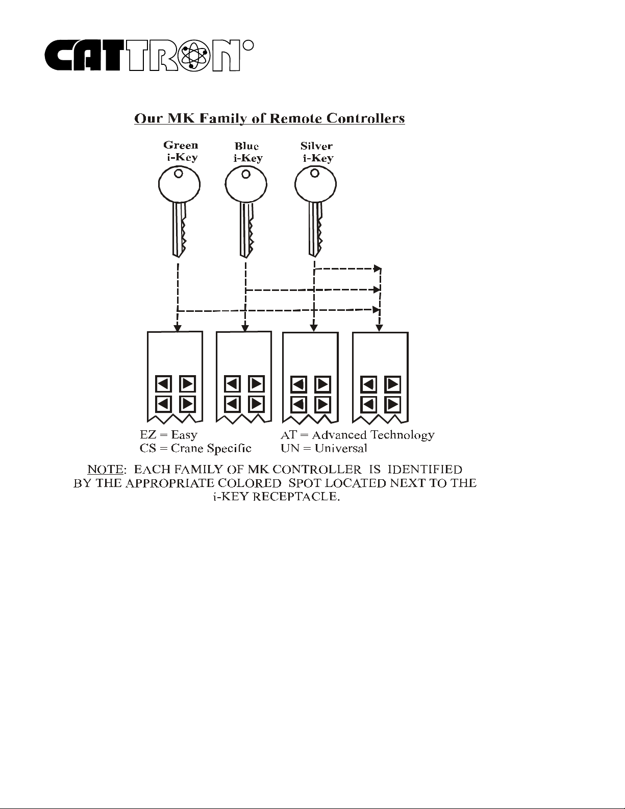
The CATTRON® Metal Keypad (MK) Series remote controller is a lightweight palm s ized, ext remely
rugged customizable radio control unit for use with any CATTRON® Portable Ra dio Remote Control
(PRRC) System. CATTRON
(Easy), CS (Crane Specific), AT (Advanced Technology) and UN (Universal).
®
MK series controllers are offered in four family configurations:
EZ
In all four CATTRON
maximum by the use of a removable stainless steel, electronic i-Key which, when installed to the
controller, defines and enables the appropriate operating parameters. When the i-Key is removed, the
controller is totally disabled.
The keypad unit and electronics are contained in an extreme duty, water resistant and dust proof
aluminum housing which has armorized rubber end-caps for switch protection and high impact
resistance. Consequently, the MK series keypad controller is able to withstand levels of impact
previously unattainable by any other portable remote controllers, without the need for carrying cases or
protect ive rubber housings. The MK controller housing is ergonomically designed with curved bottom
and rubber side grips to allow comfortable handling. The i-Key is mounted in a receptacle located
within the confines of the armorized rubber ‘bumper’ that surrounds the top end-cap. Separate
ON/OFF (green) and STOP (red) switches are also located next to the removable i-Key. A completely
sealed elastomer keypad on the controller front face contains large pushbuttons that are coated with
clear epoxy for additional durability. Each pushbutton is identified by a label that clearly indicates the
specific function for that particular key. When pressed, each pushbutton actuates a function switch
inside the controller and may be of single-step or two-step operation. Also, when pressed, each
pushbutton has a distinct limit of travel, thus providing an enhanced ta ctile fee l that is noticed by the
operator.
All commands from CATTRON
pushbutton and are absolute functions; that is, a positive ON command is sent when the button is
pressed, and a positive OFF command is sent when the same button is released. Additionally, a
mainline ON command is sent when power is turned on and a nytime a c ontroller funct ion pushbutton
is pressed. Within the MK controller, a microprocessor performs self–diagnostics, interprets
pushbutton and switch commands, and controls the radio transmitter.
®
families of MK series controllers, operational security is advanced to its
®
MK controllers respond within milliseconds of pressing a
®
CATTRON
offer 4, 8, or 12 pushbutton functions (simultaneous, any c ombination), wh ile dual-pressure models
offer 6, 12, or 16 operat or c ommande d functions (simultaneous, any c ombina tion). In addition, dualpressure models provide 2-speed operation and variable frequency drive (VFD) operation with a single
02/2000 CATTRON
MK c ontrollers are availa ble in single and dual-pressure models. Single-pressure models
®
Section 1, Page 1

R
pushbutton. All CATTRON® MK series controllers normally send on/off commands that activate
®
programmed functions at the CATTRON
receiver/decoder.
Section 1, Page 2 02/2000 CATTRON
®

R
Functional Description
, continued.
CATTRON® MK controllers are equipped with an internal antenna and the typical operating
(transmitter) range is in excess of 500 feet (160+ meters). It should be understood that operating range
varies with environmental condition s. Should the transmitter go out of operating range, all motions
will cease.
As previously mentioned, operational security is maximized by the need to use a stainless steel
electronic i-Key for controller operation. However, there is an additional and very significant
operational advantage of the CATTRON
®
i-Key concept. It is that individual system address,
operating fre quency and ke ypad configuration may be permanently stored in the i-Key, depending on
®
the type of MK controller supplied. Therefore, CATTRON
same family at a user location can be identical - only the i-Keys are different. To simplify, each i-Key
is color coded and labeled for an individual control system family, thus, any CATTRON
controller will run any CATTRON
®
receiver/decoder belonging to the same family as long as the
MK series controllers belonging to the
®
MK
correct i-Key is used. As the result, this unique operating concept reduce s the need for specific spare
remote controllers. Our unique family of MK Series controllers is identified on the next page.
All CATTRON® MK series controllers are powered by disposable 3-Volt alkaline or re-chargeable NiCad battery packs. In normal operation, a gre en LED ‘flashes’ with each function command message
and a ‘beep’ is sounded when a key is pressed. When the battery voltage becomes low, a separate
yellow LED flashes, alerting the operator that the battery pack needs to be replaced or re-charged soon.
Battery packs are easily and quickly replaced without the need for tools by turning two knurled
thumbscrews a nd removin g the battery cover-plate located within the confines of the a rmorize d rubber
bottom end-cap. The battery pac k makes positive contact without snaps or plugs and has no wires to
break; simply drop it in, and replace the battery cover-plate.
Ni-Cad battery packs can be re-charged ‘in-situ’ and do not need to be removed from the controller
housing. To enable such battery charging to be carried out, an optional ‘standard rate’ (10-hour)
battery charger is available for all CATTRON
®
MK series controllers. One end of this charger is
connected to a sta ndard 120VAC outlet, t he other plugs into a cove red socket located on t he curved
underside of the controller. A ‘rapid rate’ (1-hour) battery charger is available on request.
®
A belt loop strap is ava ilab le for all CATTRON
MK series controllers. This is qu ickly and simply
installed to a ‘D’-ring located on the curved underside of the controller. Also, an optional shoulder
carrying strap is available on request.
02/2000 CATTRON
®
Section 1, Page 3
R
EZ CS
MKEZ
(Green
i-Key)
MKCS
(Blue
i-Key)
AT
MKAT
(Silver
i-Key)
MKUN
(Any color
i-Key)
Specifications.
Case Material:
Extreme duty, water resistant and dust proof aluminum housing.
Approximate weight:
1.4lbs. / 634 grams (including battery pack).
Dimensions:
8.0" x 3.0" x 2.0" (20.0cm x 7.6cm x 5.1cm).
Environmental:
Consult CATTRON
Section 1, Page 4 02/2000 CATTRON
®
factory for a wide range of environmental solutions.
®

R
Specifications
Maximum Functions:
Single-pressure MK models:
Dual-pressure MK models:
Auxiliary functions can be added for either model:
Switch options:
4, 8, or 12 pushbuttons, single or dual pressure.
Switch type:
Sealed si licon elastomer keypad, dust, wate r, oil, acid re sistant e lastomer pad
with ‘tactile feel’, clear epoxy coated pushbuttons.
Battery life
(continuous operation)
3 Volt alkaline bat tery pack (standard) or re-chargeable Ni-Cad batte ry pack
(optional). In USA, Canada and non EU countries, battery life is:- Ni-Cad
pack – 65 hours, Alkaline pack – 150 hours. In EU countries, battery life is:Ni-Cad pack – 40 hours, Alkaline pack – 95 hours.
, continued.
4, 8, 12 (simultaneous, any combination) operator commands.
6, 12, 16 (simultaneous, any combination) operator commands.
i.e., trolley/hoist select, crane select (with i-Key only), etc.
:
Transmit indicator:
Green LED flashes with every transmission.
Low battery indication:
Yellow LED flashes for low battery, low battery alert signal beeps every 10 seconds.
Battery charging:
Internal Ni-Ca d battery charging. Optional ‘standard rat e’ (10 hour) or ‘rapid
rate’ (1-hour) battery chargers available.
Audio speaker:
For function pushbutton ‘click’ and low battery indication.
Transmitter frequency:
425-447MHz (M) or 447-473MHz (H).
02/2000 CATTRON
®
Section 1, Page 5
R
Overview – Cattron® Radio Remote Control Systems.
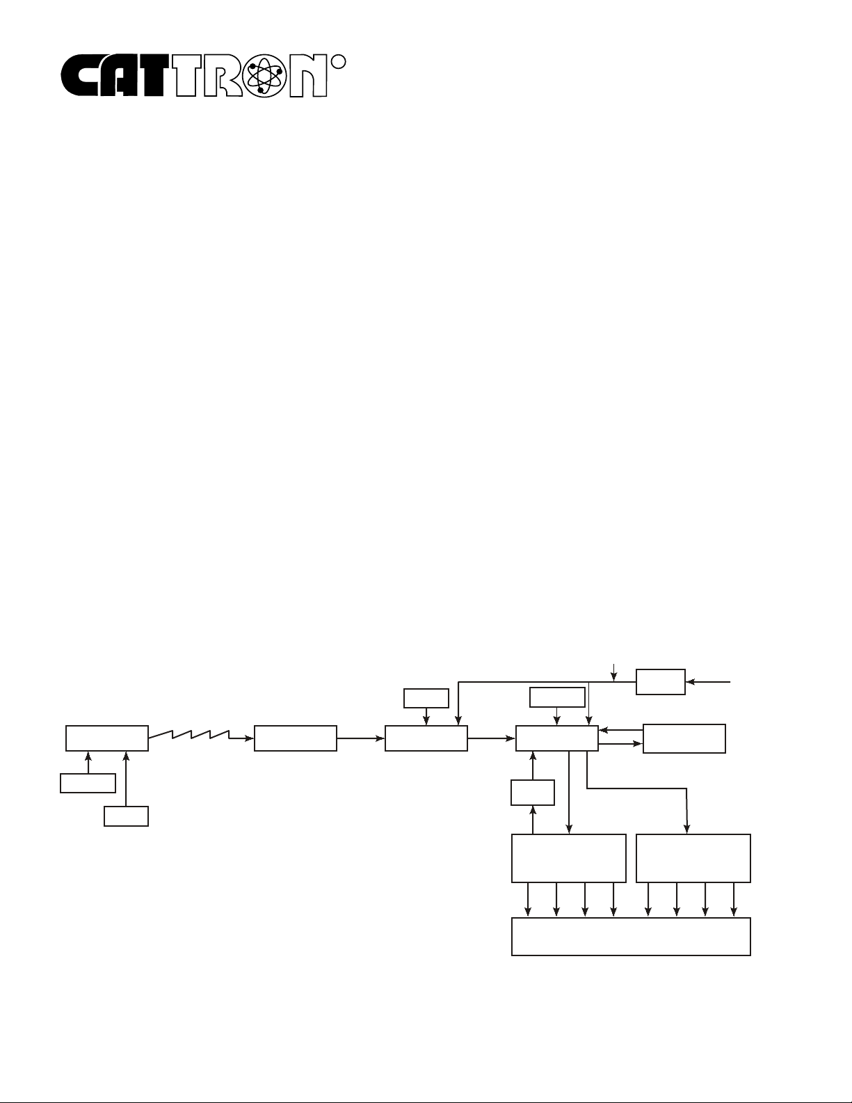
Figure 1-1 below shows a simplified block diagram of a typical CATTRON® radio remote control
system. Refer to this figure and the following paragraphs for a func tional description of the remote
control system.
The target receiver/decoder is controlled by the
MK controller
. Provided the correct
code d i-K ey
is
inserted into the keypad controller, the controller sends signals to the receiver/decoder using a UHF
radio link. The signal is picked up by the ante nna and passed on to the receiver. If the signal is the
correct frequency and passes all required data tests, the signal is passed on to the decoder.
The decoder compares the address code of the signal to its own address code. If the signal’s address
code does not match its address code, it is ignored and a message is displayed on a system status
display located in the receiver/decoder unit. If the address code is correct, the decoder processes the
message and ene rgi zes and de-energizes the appropriate control, directional output, second speed and
auxiliary function relays located within the control system.
An Automatic Safety Override (ASO) function continua lly monitors the state of any safety directional
relay output (i.e. Forward/Reverse). If a monitore d relay electrically fails closed without a command
from the controller, the ASO circuit logic de-energizes the master output relay (OPR).
During operation, the microprocessor on the decoder board resets multiple watchdog timer circuits
whenever valid messages are received and decoded. If the microprocessor fails to reset the watchdog
timers, the timer circuits shut down and de-activate all relay outputs. The decoder microprocessor
requires continuously valid transmitted signals to be received and decoded or all relay output functions
will be de-activated unless programmed otherwise.
Figure 1-1. Typical Radio Remote Control System, simplified block diagram
12 VDC
POWER
CONTROLLER
ADDRESS
FREQ
ANTENNA
FREQ
RECEIVER DECODER
ADDRESS
ASO
DIRECTIONAL
OUTPUT RELAYS
SUPPLY
SECOND SPEED AND
AUXILIARY F UNCTION
MACHINE
WIRING
115 VAC
50-60 HZ
WATCHDOG
TIMER
OUTPUT RELAYS
Section 1, Page 6 02/2000 CATTRON
®
R
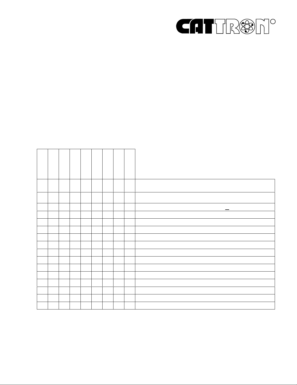
MK AT Series Keypad Controllers – Availability Options.
The various configuration s available for the CATTRON® Advanced Technology (AT) family of MK
Series Controllers are summarized below:
NOTE: This MK Controller is custom built for your remote control
application. When ordering any replacement part, provide
the following information: (1) the model and revision number
located on the serial tag underneath the controller, and (2) the
control system ID and serial number located on the i-Key
label tag.
MK (AT Family) Remote Controllers - model summary chart.
MODEL PART NUMBER
KM16DPKM12DPKM06DPKM04
111111111
--11-----
-1--1---1----1111
111111111
111111111
111111111
-------1111111111
+++++++++
111111111
+++++++++
+++++++++
+++++++++
(Suffix Codes: DP = Dual Pressure. DS = Display. +2 = additiona l function keys. S = Switch )
KM08
KM12
KM12+2KM12DSKM12
LEGEND
= NOT AVAI L ABLE
-
S
= NUMBER SUPPLIED
1
= ACCESSORY
+
Frequency Band Range From 425-447MHz (M) or 447-473MHz (H)
4 Function Buttons
8 Function Buttons
12 Function Buttons
Power On/Off Switch (green)
Internal Antenna
System Stop (red)
Liquid Cr ys tal Display
Belt Loop Carryin g Strap, 2" Black Nylon, Part Number 42C-0066
Shoulder Carryin g Strap, P art Number 42C-0057
Alkaline Battery Pack, Part Number 60C-0060A
Ni-Cad Rechargeab le Battery Pack, Part Number 60C-0060N
Ni-Cad Standard Rate (10-hr) Battery Charger, Part Number 70C-0001
Ni-Cad Rapid Rate (1-hr) Battery Charger, Part Number 70C-0002
02/2000 CATTRON
END OF SECTION
®
Section 1, Page 7
 Loading...