

Cattron North America EPH 15 Users manual
PADDLE CONTROLLER
OPERATION & MAINTENANCE INSTRUCTIONS
CUSTOMER:
MODEL NUMBER:
SERIAL NUMBER:
FREQUENCY ASSIGNMENT:
ADDRESS ASSIGNMENT:
MANUAL P/N: 68C-Paddle Rev. 004, 10/2002

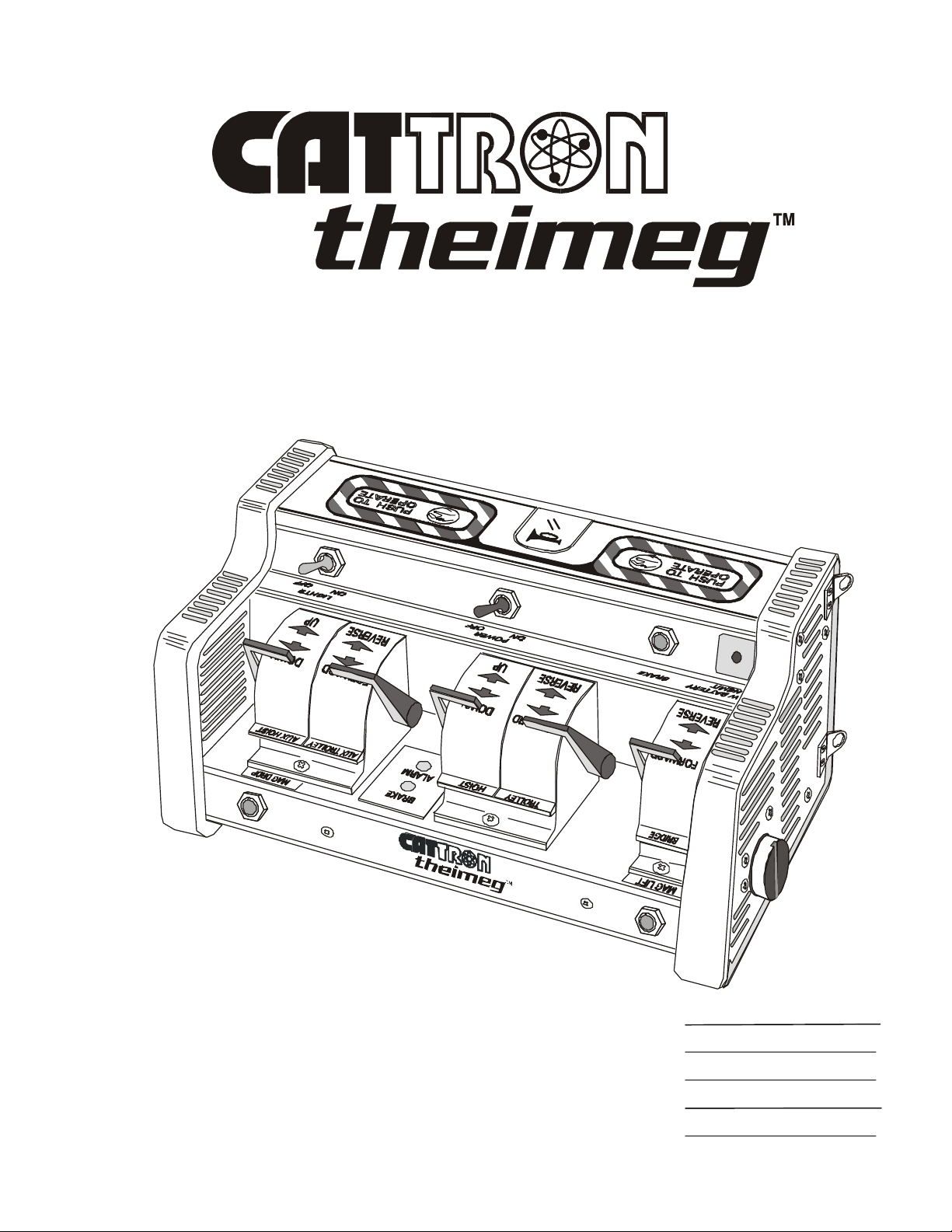
PADDLE CONTROLLER
OPERATION & MAINTENANCE INSTRUCTIONS
IMPORTANT NOTICES
Your new paddle controller has been pre-configured to operate on a specific frequency before leaving
our factory which cannot be changed by yourselves. We have assigned this frequency based upon our
existing records of control equipment previously supplied to yourselves. However, we strongly
recommend you satisfy yourselves that the frequency of your paddle controller does not match that of
any other radio remote control system located at, or around, your operating facility.
WARNING:
CATTRON-THEIMEG™ MAKES EVERY EFFORT TO ENSURE THE
ADDRESS ASSIGNED TO YOUR NEW CONTROL SYSTEM IS NOT
DUPLICATED BASED UPON RECORDS WHICH INDICATE THE ADDRESSES
OF ALL PAST PORTABLE RADIO REMOTE CONTROL (PRRC) SYSTEMS AS
SHIPPED FROM OUR FACILITY TO YOURS.
THEREFORE IT SHOULD BE FULLY UNDERSTOOD THAT WHEN A PRRC
SYSTEM HAS LEFT OUR FACTORY, CATTRON-THEIMEG™ HAS NO
CONTROL OF THE ADDRESS ASSIGNMENTS OF ANY OTHER PRRC
SYSTEM(S) THAT MAY BE IN OPERATION IN CLOSE PROXIMITY WITHIN
YOUR OPERATING AREA.
CONSEQUENTLY, AND PURSUANT TO THE ABOVE STATEMENT,
CATTRON-THEIMEG™ SHALL NOT BE HELD LIABLE FOR PERSONAL
INJURY, DEATH, EQUIPMENT OR PROPERTY DAMAGE ARISING FROM
DUPLICATED ADDRESSES OF RADIO CONTROL SYSTEMS.
©10/2002, CATTRON-THEIMEG™ Page i
Alarm ( )/optional
‘Reset’ ( ) Function
OPERATION & MAINTENANCE INSTRUCTIONS
IMPORTANT NOTICES, continued.
Your Remote Control System may include an optional ‘Reset’ function that must be activated from the
remote controller before motion control outputs are enabled on the controlled machine. You are advised
to review the customized drawing package provided with your Portable Remote Control (PRC) system
to see if this optional safety feature applies to your PRC system.
Controller
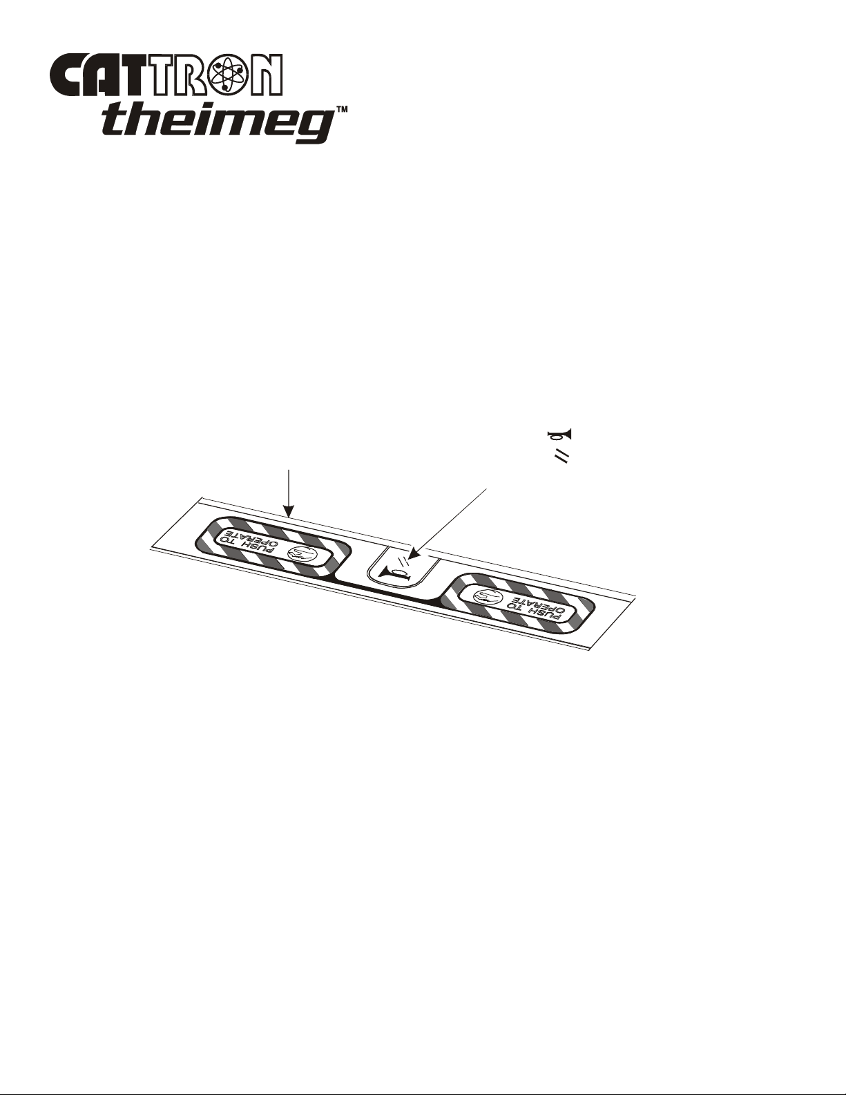
PTO Bar
Pushbutton
When this ‘Reset’ function applies to your PRC system, the momentary Alarm/Reset pushbutton located
in the center of the controller’s PTO bar must be depressed immediately after the controller has
completed its Power On Self Test, and before holding the PTO bar down to activate a motion control
function. This will sound the system horn (when connected) and reset the Main Equipment Power
Contactor.
This equipment is firmware based, including encoder, decoder, transmitter, and receiver. Any
duplication of operating firmware without written consent of CATTRON-THEIMEG™ is prohibited.
All firmware, product listings, assembly files, and this manual are protected by U.S. Copyright Laws.
As part of our continuous improvement policy, CATTRON-THEIMEG™ reserves the right to change
specifications without notice.
Page ii ©10/2002, CATTRON-THEIMEG™
List of Technical Abbreviations
The following abbreviations (acronyms) are frequently used in CATTRON-THEIMEG™ Radio
Remote Control Technology and may be used in this manual:
AC Alternating Current LED Light Emitting Diode
ASO Automatic Safety Override MK Metal Keypad
BCH Bose-Chaudhuri-
Hocquenghem (data error
detection routines)
CMOS Complimentary Metal
Oxide Semiconductor
CS Crane Specific Ni-Cad Nickel Cadmium
DC Direct Current OPR Operate
DOC Department of
Communication
DP Dual Pressure PTO Push-to-Operate
EDP Electronic Data Processing RF Radio Frequency
EEPROM Electrically Erasable
Programmable Read Only
Memory
EMI Electro-Magnetic
Interference
EOT Electrical Overhead
Traveling
ML Mainline
NEMA National Electrical
Manufacturer’s Association
PRC Portable Remote Control
RFI Radio Frequency
Interference
RST Reset Relay
SP Single Pressure
EPROM Erasable Programmable
Read Only Memory
FCC Federal Communications
Commission
GND Ground TS Transfer Switch
I/O Input/Output VAC Volts Alternating Current
IR Infra-red VDC Volts Direct Current
LCD Liquid Crystal Display VFD Variable Frequency Drive
©10/2002, CATTRON-THEIMEG™ Page iii
SYNC Synchronization
TP Test Point

Introduction
How to use this Manual.
This manual contains generic operation and maintenance procedures applicable to the entire series of
CATTRON-THEIMEG™ Radio Remote Paddle Controllers.
Because no two Paddle Controllers or Portable Remote Control (PRC) applications are exactly the same,
a General Operating Procedure is included in Section 3. This procedure is followed by Operator
Instructions for the two most popular control applications: (1) Cranes, and (2) Locomotives. By
selecting the application (1) or (2) closest to your PRC system, you should be able to familiarize
yourself with the basic operating procedures and control functions that apply to your system.
We emphasize that safety considerations are paramount when using portable remote controllers.
Accordingly, Section 2 should be read in its entirety. Also, for your consideration and possible
adoption, Recommended Safety Rules for Remote Controlled Cranes, and Recommended Safety Rules
for Radio Remote Controlled Locomotives are provided as an addendum at the end of this manual.
Page iv ©10/2002, CATTRON-THEIMEG™
Safety Summary
WARNING and CAUTION statements have been strategically placed throughout all text prior to
operating or maintenance procedures, practices or conditions considered essential to the protection of
personnel (WARNING), or equipment and property (CAUTION). A WARNING and CAUTION will
apply each time the related step is repeated. Before starting any task, the WARNINGS or CAUTIONS
included in the text for the task shall be reviewed and understood. All WARNINGS and CAUTIONS
appearing in this manual are included below.
WARNINGS.
WARNINGS:
WITH THE EXCEPTION OF LOCOMOTIVES, ALL EQUIPMENT MUST
HAVE A MAINLINE (ML) CONTACTOR INSTALLED AND ALL TRACKED
EQUIPMENT (i.e. CRANES) HAVE A BRAKE INSTALLED.
THE REMOTE CONTROL OPERATE (OPR) RELAY MUST BE CONNECTED
TO THE MAINLINE SO THAT STOP COMMANDS OR FAULT CONDITIONS
MONITORED BY AUTOMATIC SAFETY OVERRIDE (ASO) CIRCUITRY
WILL DE-ENERGIZE THE MAINLINE CONTACTOR AND SET THE
EQUIPMENT BRAKE.
FAILURE TO COMPLY WITH THE ABOVE WARNINGS MAY RESULT IN
SERIOUS INJURY OR DEATH TO PERSONNEL AND DAMAGE TO
EQUIPMENT.
WARNING:
MORE THAN ONE REMOTE CONTROL SYSTEM MAY BE USED AT,
AROUND, OR NEARBY YOUR OPERATING FACILITY. THEREFORE, YOU
MUST INSURE THE ADDRESS CODE AND FREQUENCY OF YOUR
PADDLE CONTROLLER EXACTLY MATCHES THE ADDRESS CODE AND
FREQUENCY OF THE DESIRED EQUIPMENT TO BE OPERATED.
FAILURE TO COMPLY WITH THE ABOVE WARNING MAY RESULT IN
THE UNDESIRED OPERATION OF OTHER EQUIPMENT WHICH, IN
TURN, COULD RESULT IN SERIOUS INJURY OR DEATH TO PERSONNEL
AND DAMAGE TO EQUIPMENT.
WARNING:
NEVER DISABLE THE PUSH TO OPERATE (PTO) BAR SWITCH ON YOUR
REMOTE CONTROLLER. FAILURE TO COMPLY WITH THIS WARNING
MAY RESULT IN DAMAGE TO EQUIPMENT, SERIOUS INJURY, OR
DEATH.
©10/2002, CATTRON-THEIMEG™ Page v
WARNINGS, continued.
WARNING:
ON CAB AND REMOTE OPERATED CRANES OR CARRIERS AN AUDIBLE
OR VISUAL WARNING MEANS SHALL BE PROVIDED. IN ADDITION, ALL
EQUIPMENT SHALL HAVE AUDIO OR VISUAL ALARM INDICATIONS
MEETING GOVERNMENTAL REQUIREMENTS. FAILURE TO
IMPLEMENT THIS WARNING MAY RESULT IN SERIOUS INJURY OR
DEATH TO PERSONNEL AND DAMAGE TO EQUIPMENT.
WARNINGS:
UNCODED ADDRESS PLUG(S) SHALL BE PROGRAMMED WITH THE
SAME ADDRESS CODE AS SET IN THE TARGET RECEIVER/DECODER.
IT SHOULD BE FULLY UNDERSTOOD THAT CATTRON-THEIMEG™
SHALL NOT BE HELD LIABLE FOR PERSONAL INJURY, DEATH,
EQUIPMENT OR PROPERTY DAMAGE ARISING FROM DUPLICATED,
INCORRECTLY PROGRAMMED OR INCORRECT CODE PLUG USAGE.
IT IS YOUR RESPONSIBILITY TO ESTABLISH A PROCEDURE THAT
INSURES ONLY THE CODE PLUG CONFIGURED FOR A PARTICULAR
ADDRESS IS INSTALLED IN EQUIPMENT DESIGNED TO OPERATE ON
THE SAME ADDRESS. NEVER PUT MORE THAN ONE CONTROLLER
INTO OPERATION ON THE SAME ADDRESS AT ANY GIVEN TIME.
CATTRON-THEIMEG™ STRONGLY ADVISES YOU TO IMPLEMENT AND
REGULARLY UPDATE A REGISTER OF INDIVIDUAL ADDRESSES AND
OPERATING FREQUENCIES ASSIGNED TO EACH PORTABLE RADIO
REMOTE CONTROL (PRRC) SYSTEM LOCATED AT YOUR OPERATING
FACILITY. IN ADDITION, ANY SPARE CODE PLUGS, OR CODE PLUGS
INSTALLED IN EQUIPMENT THAT ARE CONFIGURED FOR THE SAME
ADDRESS OF EQUIPMENT THAT IS IN SERVICE, MUST BE HELD UNDER
LOCK AND KEY BY A DESIGNATED SUPERVISOR.
FAILURE TO COMPLY WITH THESE WARNINGS MAY RESULT IN
OPERATION OF UNDESIRED EQUIPMENT WHICH IN TURN COULD
RESULT IN SERIOUS INJURY OR DEATH TO PERSONNEL AND DAMAGE
TO EQUIPMENT.
Page vi ©10/2002, CATTRON-THEIMEG™
WARNINGS, continued.
WARNINGS:
ALL TRACKED EQUIPMENT (i.e. LOCOMOTIVES) MUST HAVE A BRAKE
INSTALLED.
THE REMOTE CONTROL OPERATE (OPR) RELAY MUST BE
CONFIGURED SO THAT STOP COMMANDS OR FAULT CONDITIONS
MONITORED BY AUTOMATIC SAFETY OVERRIDE (ASO) CIRCUITRY
WILL SET THE THROTTLE TO IDLE, DISCONNECT THE GENERATOR
FIELD, AND SET THE INDEPENDENT BRAKE.
FAILURE TO COMPLY WITH THE ABOVE WARNINGS MAY RESULT IN
SERIOUS INJURY OR DEATH TO PERSONNEL AND DAMAGE TO
EQUIPMENT.
WARNING:
AFTER CHANGING AN ADDRESS OR FREQUENCY SELECTOR SWITCH,
YOU MUST, IN THE FIRST INSTANCE, INSURE THE TARGETED
MACHINE IS UNDER REMOTE CONTROL BEFORE OPERATING ANY
MOTION FUNCTION SWITCH. THIS MAY BE ACCOMPLISHED BY
OPERATING A NON MOTION FUNCTION SWITCH ON THE REMOTE
CONTROLLER SUCH AS A HORN OR LIGHT.
FAILURE TO COMPLY WITH THE ABOVE WARNING MAY RESULT IN
THE UNDESIRED OPERATION OF OTHER EQUIPMENT WHICH, IN
TURN, COULD RESULT IN SERIOUS INJURY OR DEATH TO PERSONNEL
AND DAMAGE TO EQUIPMENT.
WARNING:
ELECTRICAL POWER TO THE TARGET CONTROLLED EQUIPMENT
MUST BE COMPLETELY ISOLATED TO PREVENT OPERATION UNDER
REMOTE CONTROL IN THE SWITCH DIAGNOSTIC MODE.
FAILURE TO COMPLY WITH THE ABOVE WARNING MAY RESULT IN
THE UNDESIRED OPERATION OF EQUIPMENT WHICH, IN TURN, COULD
RESULT IN SERIOUS INJURY OR DEATH TO PERSONNEL AND DAMAGE
TO EQUIPMENT.
©10/2002, CATTRON-THEIMEG™ Page vii

WARNINGS, continued.
WARNING:
DUE TO FCC PART 15 AND DOC RSS-210 RADIO TRANSMIT
REGULATIONS, THE OPR OUTPUT TO WHICH YOUR CONTROLLED
EQUIPMENT’S MAINLINE CONTACTOR IS CONNECTED WILL REMAIN
ENERGIZED FOR TEN MINUTES AFTER THE CONTROLLER POWER IS
SET TO ‘OFF’, OR FOR TEN MINUTES AFTER THE LAST TIME A
FUNCTION SWITCH IS ACTIVATED. CONSEQUENTLY, SPECIAL CARE
MUST BE TAKEN IF THE CRANE OR TRACKED MACHINE IS EQUIPPED
WITH A PARKING BRAKE THAT IS CONFIGURED TO ENGAGE WHEN
THE MAINLINE CONTACTOR DE-ENERGIZES.
TO PREVENT A POTENTIALLY HAZARDOUS SITUATION, YOU SHOULD
IMMEDIATELY SELECT THE RED ‘STOP’ FUNCTION ON YOUR
REMOTE CONTROLLER AFTER COMPLETION OF OPERATIONS. SUCH
ACTION WILL INSURE THE PARKING BRAKE (IF EQUIPPED AND
CONFIGURED AS ABOVE) IS SET, PREVENTING UNINTENTIONAL
MOVEMENT OF THE CRANE OR TRACKED MACHINE.
FAILURE TO COMPLY WITH THIS WARNING MAY RESULT IN SERIOUS
INJURY OR DEATH TO PERSONNEL AND DAMAGE TO EQUIPMENT.
CAUTIONS.
CAUTIONS:
(1) CATTRON-THEIMEG™ Battery Conditioners are designed for use with
(2) Battery Packs must be removed or disconnected from Battery Conditioners
Failure to comply with these Cautions may result in equipment and/or battery
damage and will void our warranty.
CATTRON-THEIMEG™ Ni-Cad Battery Packs only.
within 48-hours of achieving the fully charged state.
Page viii ©10/2002, CATTRON-THEIMEG™

Safety Summary, continued
GENERAL.
The following are general safety precautions that are not related to any specific procedure and therefore
do not appear elsewhere in this manual. These are general safety precautions and instructions that
people must understand and apply during many phases of operation and maintenance to ensure personal
safety and health and the protection of your company property.
KEEP AWAY FROM LIVE CIRCUITS. Maintenance personnel must observe all safety
requirements at all times. Do not replace components or make adjustments inside the equipment with
the electrical supply turned on. Under certain conditions, danger may exist even when the power control
is in the off position due to charges retained by capacitors. To avoid injuries, always remove power,
discharge and ground a circuit before touching it. Adhere to all lock out/tag requirements.
DO NOT SERVICE OR ADJUST ALONE. Do not attempt internal service or adjustment of
equipment unless another person capable of rendering aid and resuscitation is present.
FINGER RINGS/JEWELRY. Finger rings have caused many serious injuries. Remove rings,
watches and other metallic objects which may cause shock or burn hazards.
SOLDERING/DE-SOLDERING. Avoid breathing fumes generated by soldering/de-soldering.
Perform all operations in a ventilated area. Eye protection is required.
CLEANING SOLVENTS. Some cleaners and solvents have adverse effects on skin, eyes, respiratory
tract and internal organs. These adverse effects range from discomfort to serious injury and death,
depending on the material and degree of exposure. Observe manufacturers’ warning labels and contact
your immediate supervisor if in any doubt.
Remember…. the person now reading these instructions
is primarily responsible for his or her own health and
safety.
©10/2002, CATTRON-THEIMEG™ Page ix

This page intentionally left blank
Page x ©10/2002, CATTRON-THEIMEG™

Table of Contents
Front Matter:
Important Notices ............................................................................................................ i
List of Technical Abbreviations .................................................................................... iii
How to use this Manual ................................................................................................ iv
Safety Summary .............................................................................................................. v
Warnings ........................................................................................................... vi
Cautions .......................................................................................................... viii
General .............................................................................................................. ix
Section 1 – Product Data and Specifications:
Introduction ................................................................................................................. 1-1
Notable Performance and Safety features ................................................................... 1-2
Frequently asked questions ......................................................................................... 1-3
Standard Specifications ............................................................................................... 1-5
Overview of CATTRON-THEIMEG™ Remote Control Systems .............................. 1-7
Section 2 – Safety Information:
Safety Considerations ................................................................................................. 2-1
Safety and Security Features ........................................................................... 2-1
Typical Method of Operation incorporating ................................................... 2-2
Safety & Security Features
Radio Control Operator’s Duties – General Equipment ............................................. 2-4
Radio Control Operator’s Duties – E.O.T. Crane ....................................................... 2-8
Radio Control Operator’s Duties – Locomotive ....................................................... 2-12
Section 3 – Operating Instructions:
Controls and Indicators ............................................................................................... 3-1
General Operating Procedure ...................................................................................... 3-5
Typical Crane Control Functions .............................................................................. 3-10
Typical Locomotive Control Functions .................................................................... 3-13
Switch Diagnostic Mode ........................................................................................... 3-17
©10/2002, CATTRON-THEIMEG™ Page xi

Section 3 – Operating Instructions, continued:
Battery Packs and Battery Pack Charging ................................................................ 3-18
Battery Pack Replacement ............................................................................ 3-18
Battery Pack Conditioning/Charging – Ni-Cad Battery packs only ............. 3-20
Pre-Programmed Frequency Selection ..................................................................... 3-22
Pre-Programmed Option Selection ........................................................................... 3-25
Section 4 – Maintenance Instructions:
CATTRON-THEIMEG™ Maintenance Philosophy ................................................... 4-1
Preventive Maintenance .............................................................................................. 4-1
Troubleshooting .......................................................................................................... 4-2
Troubleshooting Guide ................................................................................... 4-3
Corrective Maintenance .............................................................................................. 4-4
Functional Check ........................................................................................................ 4-4
Replacement Items ...................................................................................................... 4-4
Battery Pack .................................................................................................... 4-4
Address Code Plug .......................................................................................... 4-5
Side Lever (optional item) .............................................................................. 4-9
External Antenna (optional item) .....................................................................4-9
Section 5 – Replacement Items and Accessories:
Replacement Items ..................................................................................................... 5-1
Consumable Items and Optional Accessories ............................................................. 5-3
Index.
Appendices:
1. RECOMMENDED SAFETY RULES FOR PORTABLE REMOTE
CONTROLLED (PRC) CRANES.
2. RECOMMENDED SAFETY RULES FOR PORTABLE RADIO REMOTE
CONTROLLED (PRRC) LOCOMOTIVES.
Page xii ©10/2002, CATTRON-THEIMEG™

Section 1 – Product Data & Specifications
Introduction.
The CATTRON-THEIMEG™ Paddle Controller has a unique shape and style that provide the equipment
operator with a controller that is extremely durable, convenient, and easy to operate. Designed
specifically for heavy duty in harsh working environments, the controller is ideally suitable for both
indoor and outdoor remote control applications within the steel, glass, automotive, shipping, mining,
distribution, and railroad industries. It can be used with all CATTRON-THEIMEG™ AT Series or MP
Series receiver/decoder units as well as being used with existing CATTRON-THEIMEG™ PRRC
systems as either a replacement or spare controller.
Your paddle controller is designed to duplicate the operating characteristics of the controls most
commonly found on the controlled machine, therefore the change from manual to radio remote control is
easily learned by the operator.
The CATTRON-THEIMEG™ paddle controller employs advanced micro-computer electronics and
utilizes surface mount technology. A highly advanced encoder circuit board is built using industrial
grade components and incorporates a powerful microcomputer that uses sophisticated operating
software. The main housing that surrounds and protects the electronic circuitry is made of thick walled,
extruded aluminum with a protective exterior coating. The ends of the housing are rubber-coated plates
that make shock absorbing end ‘bumpers’ and switch/lever guards. Only the highest quality industrial
grade and ‘mil-spec’ switches whose reliability and construction have been field-tested and proven
under extreme conditions are used in your paddle controller. Total water and dust sealing makes these
switches suitable for indoor and outdoor operation.
CATTRON-THEIMEG™ paddle controllers have room for up to six paddles and can be customized with
additional pushbuttons and toggle switches. In addition, all functions are identified by durable custom
engraved nameplates.
A variety of synthesized and crystal-controlled RF transmitter configurations can be provided with this
controller, allowing operation on licensed and non-licensed VHF and UHF radio channels. In addition,
all CATTRON-THEIMEG™ paddle controllers meet the FCC's requirements regarding narrow band and
12.5 kHz bandwidths.
©10/2002, CATTRON-THEIMEG™ Section 1, Page 1

Notable Performance and Safety Features.
POWER ON SELF TEST (POST) DIAGNOSTICS - When the operator first turns the power switch on,
a sophisticated self-test routine tests the microcomputer and all function switch inputs to detect
unwanted commands in the system. All lever style switches are tested for neutral at this time. A small
speaker beeps twice when the test has been completed satisfactorily.
TRANSMIT/BATTERY CHARGE INDICATOR - The low battery detection circuit is a two stage
design. With a good battery, this indicator light flashes green for each burst of transmitted data. If the
battery voltage drops below the normal level, this LED flashes red during each transmission. A beeping
sound every 10 seconds alerts the operator. When this happens, the battery has approximately one hour
of operating time remaining. The controller stops transmitting before the voltage drops so low that
erratic operation could occur.
BATTERY SAVER – If the controller has not been operated for 15 minutes, a battery management
system detects this inactivity and puts the controller into a ‘deep sleep’ mode. To reset the controller,
the POWER ON/OFF SWITCH must be set to ‘OFF’, and then set to ‘ON’ again.
BATTERY PACK OPTIONS – Alkaline (disposable) & Ni-Cad (rechargeable) battery packs are
available from CATTRON-THEIMEG™. Whether you choose disposable or rechargeable battery
packs, changing the battery pack is easy - simply unlatch and open the gasketed battery door, drop the
battery pack in place and close and latch the battery door. There are no wires or connectors to insert into
the battery pack, which improves long-term reliability of this unit.
RUGGED HOUSING - The housing that surrounds and protects the electronic circuitry is a thick-walled
extruded aluminum, which has a hard epoxy powder coated exterior. The ends of the housing are rubber
coated plates that make shock absorbing end 'bumpers’.
DURABLE/OUTDOOR OPERATION – All switches are extremely long life units that are sealed,
providing water and dust protection. All modules and sub-components are gasketed, making your
controller suitable for outdoor operation in rain and snow.
LEVER AND SWITCH PLACEMENT - Each layout is customized according to user needs. The
switch levers are placed far enough apart to accommodate operators who wear heavy gloves.
SAFETY BAR - A long safety bar is provided to function as an enable device to all motion control
switches. It is a large full-length switch that is easily and naturally activated by a convenient and
comfortable part of the operator's hand any time he or she activates a motion switch. This push-tooperate (PTO) safety bar electronically disconnects all motion switches when it is released, thus
stopping motion commands from these switches. This feature is programmable as some applications
may have lever switches removed from control of the PTO bar. An example of this would be some
locomotive braking functions.
ALARM/RESET FUNCTION (optional) – Your remote controller may incorporate this additional
safety function connected to the momentary pushbutton located in the center of the PTO Safety Bar.
Check the system drawings provided with your remote control system to see if this optional feature
applies to your controller. When applicable to your controller, this pushbutton must be depressed
immediately after the controller has completed its Power On Self Test and before holding the PTO Bar
down to activate a motion control function. This will sound the system horn (when connected) and reset
the main Equipment Power Contactor.
Section 1, Page 2 ©10/2002, CATTRON-THEIMEG™

Notable Performance and Safety Features, continued.
LEVER GUARD BAR (optional) – When additional lever switch protection against physical damage is
required, this fixed bar extends upwards from both ends and across the front of the controller.
INTERNAL TILT SWITCH – If the controller is tilted in any axis beyond 60 degrees of upright for
longer than the programmed time (typically 3 seconds), a programmable function is sent automatically.
This function can be assigned in the decoder to stop the equipment, sound an alarm, or both. Reset time
is also programmable.
OPERATING FREQUENCIES - A variety of RF transmitters are available allowing controller
operation in 72-76 MHz, 402-420 MHz, and 450-470 MHz bands on licensed radio channels and 447471 MHz on unlicensed channels. Most models in the 450 MHz range are synthesized (16 frequency
channels maximum).
APPLICATIONS - The paddle controller can operate any digital series receiver/decoder built by
CATTRON-THEIMEG™. It can be used with existing CATTRON-THEIMEG™ systems as a
replacement or as an extra transmitter/encoder.
Frequently Asked Questions.
Refer to Table 1-1 below for the most frequently asked questions about your paddle controller.
Table 1-1. Paddle Controller, questions and answers
QUESTION ANSWER
SAFETY
Protection against operator
becoming disabled or falling down?
Protection against accidental switch
operation?
Simple operation by position and
feel (without looking at controller)?
High quality custom labeling? YES – Customized text and arrows, large size, durable mylar
Number of functions sent to activate
a motion?
Protection against false commands
or data as battery discharges?
Protection against stray radio signals
and other Remote Control systems?
Protection against other digital data
radio (e.g.. pagers, cell, fax) or
radiation from computer equipment?
Protection against broken switches
or wiring sending motion
commands?
YES - fitted with a tilt switch and Push to Operate (PTO) safety bar switch
as standard
YES - PTO safety bar switch and toggle switches are protected by housing
design. Spring return to OFF
YES - Levers are large enough for easy glove operation. Unique shape
knobs available. Detent for speed steps (5)
TWO (lever and PTO)
YES - Low battery warning, then cut off prior to reaching unstable levels
YES - Unique digital address sent at the beginning of each data message.
YES - Unique (non-standard) data baud rate, each motion command has
data in at least two bytes, very complex data error detection (BCH)
YES - Switches (potentiometers) are tested for neutral at power on and for
open or shorted wiring before each digital message. Potentiometers tested
for travel beyond end of range and digital A/D converters tested constantly
Withstand static discharge and high
magnetic fields?
YES - Unit tested for EMI/RFI by independent lab. Passes and can carry
CE mark. Has been used successfully in high magnetic fields.
©10/2002, CATTRON-THEIMEG™ Section 1, Page 3

Frequently Asked Questions, continued.
Table 1-1. Paddle Controller, questions and answers
QUESTION ANSWER
RELIABILITY
Durable case material? YES - Aluminum with epoxy coating. ‘Neoprene’ rubber bumper ends
Enclosure water/dust/oil resistant? YES - NEMA 12 (IP-65)
Long motion switch operating life? YES – Greater than 1 million operations
Reliable switch wiring? YES – Switches are potentiometers, wired using silver coated multi-strand
teflon coated wire and gold plated connectors. Only 3 wires per ‘switch’
Simple and reliable electrical
connection method to battery?
Ability to survive repeated drops on
to concrete floor?
Maximum number of function speed
steps per motor available?
State of the art electronic construction
techniques?
MAINTAINABILITY
High quality component grades used? YES - Industrial and mil-spec
Internal antenna? YES – Slot design, printed circuit board construction, integral part of lower
Operator diagnostics - battery
condition indication?
Operator diagnostics - determining
switch operation condition?
Data transmit indicator? YES – GREEN LED flashes with each message being sent (will normally
YES - Stainless steel contacts that mate with stainless pads on battery.
Automatic wiping at each insertion into controller
YES - Tested by UL labs to mil-specs. Drops will not cause motion
Uses potentiometers for all motion functions - 5 step each direction or
stepless typical
YES - Machine built PC board (1) using surface mount components
primarily
front housing on unlicensed controllers. Optional external antennas
available.
YES - TWO stage battery condition indicator: flash GREEN – OK. Flash
RED – battery needs changing, audible beeps every 10 seconds anytime
red indicator is flashing.
YES - Can be placed in switch beep mode by turning on power while unit
is tilted. Beep when a motion control function switch is operated indicates
switch functioning correctly.
be synchronized with receiver LED's)
Easy Disassembly and Assembly? YES - by CATTRON-THEIMEG™ trained customer technicians only.
Minimal wires and few connections
PC diagnostics capability? YES - by CATTRON-THEIMEG™ trained customer technicians only. PC
testing port, cable, and diagnostic software available. Helps real time
troubleshooting
Test method for RF frequency,
modulation and related tests?
YES - by CATTRON-THEIMEG™ trained customer technicians only. Unit
can be placed in a special test mode by holding PTO bar down while
turning on power (also prevent operator tampering)
Section 1, Page 4 ©10/2002, CATTRON-THEIMEG™

Frequently Asked Questions, continued.
Table 1-1. Paddle Controller, questions and answers
QUESTION ANSWER
OPERATIONAL FEATURES
FCC approval for narrow band
licensed operation in new 12.5 kHz
channels?
Operational range without Close
Start or Range limited receiver
/decoder (Maximum distance)?
Special display features for operator? YES - LED (day/night) optional - selects data to be sent e.g., door number
Weight? 3-paddle unit (P03) weighs approximately 6.5 pounds with battery pack.
Carrying methods available to
provide comfortable, (all day)
operation?
YES - Approved for both non-licensed and licensed services with ongoing
designs for changing USA and Canadian rules and regulations.
Transmitters can be assigned 12.5kHz channels. In addition, units have a
wide number of approvals and frequency ranges for European, UK and
Australian operation
Low power (unlicensed) units typically 300 feet for operation indoors in an
industrial environment. 500 feet outdoors under best conditions
Licensed units typically 800 to 1000 feet indoors. Higher power M840
option is available for operation up to 1 mile outdoors, depending on a
variety of operational and environmental factors which may reduce the
actual operating range. A typical example of the above would be a
locomotive application with TALKBACK™ operating at 330 mW using an
‘on board’ 5dB antenna.
to control. LCD or individual LED's available for Talkback
Optional lightwieght end-caps available which will reduce weight by 1 lb
YES - Normally carried using a belt and shoulder harness combination.
This places the unit at the belly. A back support (wide elastic) belt and
shoulder harness combination is optional
Standard Specifications.
Case Material: Epoxy powder coated Anodized Aluminum Extrusion with Molded
Rubber End Caps.
Weight: 3-Paddle Unit (P03) - approximately 6.5 lbs. (3 Kgs), including Battery
Pack.
Dimensions: 3-Paddle Unit (P03) - Height: 5.9" (15 cm) Depth: 6.7" (17 cm) Width:
9.5" (24 cm).
Environmental: -4° F to +140° F (-20° C to +60° C), RH 0 to 95% Non-condensing.
Switch Types: Spring Return to Center Toggle, Maintained Toggle, Momentary
Pushbutton, Rotary Select.
Lever Switch Detented (5-steps each side of center) or Stepless (analog) Spring Forward
Choices: Idle and 8-steps for Throttle, Etc.
Lever Styles: Large Flag. Special Shaped Lever Knobs Optional.
©10/2002, CATTRON-THEIMEG™ Section 1, Page 5

Standard Specifications, continued.
Number of Motor 3 (3-Paddle), 4 (4-Paddle), 5 (5-Paddle), or 6 (6-Paddle). Additional
Functions: motor functions are available – contact your CATTRON-THEIMEG
sales representative for details
Auxiliary
Functions: 15 digital ON/OFF.
Push To Operate
Safety Bar: Standard.
Lever Guard Bar: Optional – extends from both sides across the front above the levers.
Labeling: Mylar, Multi-layer, Large
Keylock Switch: Optional (Power ON/OFF).
Antenna: Internal (external optional).
Low Battery
Indicator: 2 Color LED: GREEN - Battery Normal, RED - Battery Low.
Short Circuit
Protection: Automatically Resetable Polyswitch (no fuses).
Conformal Coating: Standard on PC Board.
Transmitter
Frequency: Synthesized and Crystal Control Models
72-76 MHz, 402-420 MHz, or 450-470 MHz - License Required.
447-471 MHz - No License Required.
Power Output: 450-470 MHz: typically between 20 and 40 mW.
402-420 MHz: typically between 20 and 40 mW.
72-76 MHz: 60 mW Nominal.
447-471 MHz: Maximum According to FCC Rules Part 15.
402-420 MHz, or 450-470 MHz M840 transmitter/transceiver
(licensed) option adjustable from 80-450 mW
Synthesized
Channels: 16 Maximum (Factory Programmed).
™
Section 1, Page 6 ©10/2002, CATTRON-THEIMEG™
Overview – CATTRON-THEIMEG™ Radio Remote Control Systems
MAINS INPUT
™
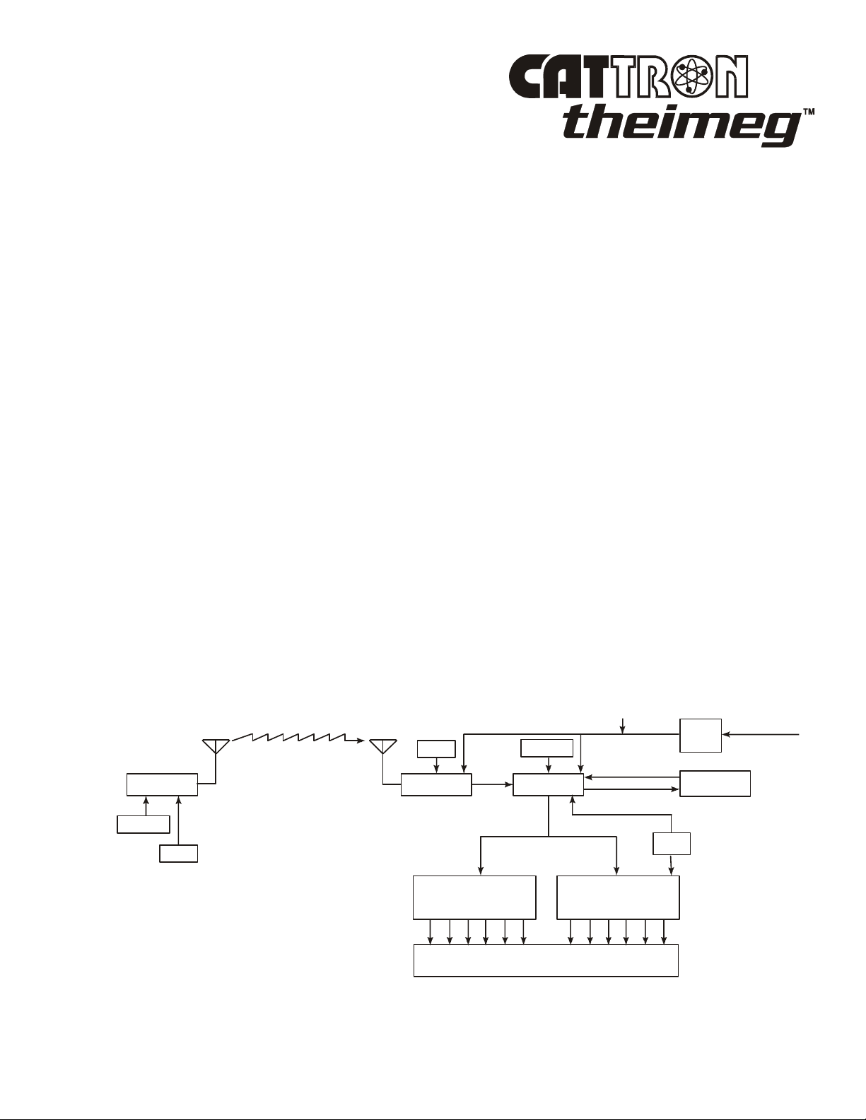
Figure 1-1 below shows a simplified block diagram of a typical CATTRON-THEIMEG
control system. Refer to this figure and the following paragraphs for a functional description of the
remote control system.
The target receiver/decoder is controlled by the Paddle Controller, which sends signals to the
receiver/decoder using a UHF radio link. The signal is picked up by the antenna and passed on to the
receiver. Provided the frequency of the paddle controller exactly matches that of the target receiver and
passes all data tests, the signal is passed on to the decoder.
The decoder compares the address code of the signal to its own address code. If the signal’s address
code does not match the decoder’s address code, it is ignored and a message is displayed on a system
status display usually located in the receiver/decoder unit. If the address code is correct, the decoder
processes the message and energizes and de-energizes the appropriate control and auxiliary function
relays located within the control system.
An Automatic Safety Override (ASO) function continually monitors the state of any directional relay
output (i.e. Forward/Reverse). If a monitored relay electrically fails closed without a command from the
controller, the ASO circuit logic de-energizes the master output relay (OPR) which should be connected
to the mainline contactor of your controlled machine.
During operation, the microprocessor on the decoder board resets multiple watchdog timer circuits
whenever valid messages are received and decoded. If the microprocessor fails to reset the watchdog
timers, the timer circuits shut down and de-activate all relay outputs. The decoder microprocessor
requires continuously valid transmitted signals to be received and decoded or all relay output functions
will be de-activated unless programmed otherwise. It should be noted that the mainline control relay
(OPR) may be maintained for up to 10 minutes, depending on system configuration.
radio remote
Figure 1-1. Typical Radio Remote Control System - simplified block diagram
CONTROLLER
ADDRESS
FREQ
Tx
Rx
FREQ
RECEIVER
AUXILIARY FUNCTION
OUTPUT RELAYS
ADDRESS
DECODER
OUTPUT RELAYS
MACHINE WIRING
12 VDC
POWER
SUPPLY
WATCHDOG
TIMER
ASO
DIRECTIONAL
50-60 HZ
END OF SECTION
©10/2002, CATTRON-THEIMEG™ Section 1, Page 7

This page intentionally left blank
Section 1, Page 8 ©10/2002, CATTRON-THEIMEG™

Section 2 – Safety Information
Safety Considerations.
CATTRON-THEIMEG™ believes that to safely operate any remotely controlled equipment, the overall
system needs to be configured so that movement or operation of the equipment will take place only
when the device is commanded to move or operate. For example, overhead cranes or locomotives must
be equipped with a braking system that can only be released when an electrical signal is sent to the
motor. Removal of electrical power or loss of the radio transmitted signal results in application of the
brakes. On cranes, this is provided when a CATTRON-THEIMEG™ Electro-Hydraulic brake package
is installed – contact the factory for details. On locomotives, an air valve opens, applying independent
braking and the throttle returns to idle.
In keeping with this philosophy - NO COMMAND, NO MOVEMENT - CATTRON-THEIMEG™ has
designed your radio remote control system with the following safety and security features which may, at
your request, be modified to meet specific operating requirements. CATTRON-THEIMEG™ engineers
are always available to work with you to provide optimum operating system safety.
Safety & Security Features.
Unique address code: Each controller and receiver/decoder pair is configured with a
unique address code so that the equipment will respond only to the controller whose
address code matches that of the decoder.
Intelligent digital message protocol: CATTRON-THEIMEG™ remote control systems
utilize a unique message protocol for industrial control applications rather than the
customary Electronic Data Processing (EDP) type of message format.
Power ON/OFF switch: The controller has a power ON/OFF Key or Toggle Switch that
must be set to ‘ON’ in order to send commands to the receiver/decoder. If the power
ON/OFF Switch is set to ‘OFF’, the decoder will remove all commands from the
controlled machinery, stopping all movement. However, the mainline control relay (OPR)
may be maintained for up to 10 minutes, depending on system configuration.
Operate relay (OPR): The operate (OPR) output relay shall be wired to control a userprovided electro-magnetic power contactor. The electro-magnetic contactor opens and
closes the main electrical supply circuit(s) to the controlled device.
Automatic Safety Override: The Automatic Safety Override (ASO) function continually
monitors all selected decoder directional relay outputs. If a directional relay closes without
command from the controller, the Operate (OPR) Relay immediately de-energizes. This
prevents any movement of the controlled machine without command from the controller.
©10/2002, CATTRON-THEIMEG™ Section 2, Page 1

Safety & Security Features, continued.
Data Error Checking: All communications from the controller to the receiver/decoder
contain error-checking information (BCH data error detection routines). The entire data
command packet must pass error detection tests before being processed.
Push-To-Operate (PTO) Bar: This easily activated switch bar must be released when
power is turned on, then pressed and held to enable the motion switch functions. Releasing
the PTO during normal operation causes the controller to send neutral commands to the
receiver/decoder. In certain cases the PTO will be programmed NOT to enable or disable a
particular function switch, i.e. some locomotive braking functions. Refer to the schematic
drawing for your custom controller serial number to understand its configuration.
NOTE: Holding the PTO bar down when power is turned on places the
controller in a technical diagnostic mode. Refer to Maintenance
Instructions (Section 4) for details.
Optional ‘Keyless Entry Code’: This available feature requires an operator to activate a
series of switches correctly before the controller power is turned on.
Typical method of operation (incorporating above safety features).
The Operate (OPR) relay is energized for the first time when:
The controller’s Power ON/OFF Switch is set to ‘ON’ and the target receiver/decoder has power
applied. With these conditions satisfied, a matching address code is sent by way of RF signal from the
controller to the decoder.
The OPR relay is wired to the mainline (ML) contactor on the crane. Once the mainline is energized, a
continuously repeated valid signal must be received for function outputs to engage. If this signal is
interrupted for any reason, all function outputs will turn off unless programmed otherwise.
When operating within the USA, FCC rules state that RF transmitters in non-licensed controllers must
switch off within five seconds after the operator releases a function button. Consequently, the OPR
output is programmed to stay on for ten minutes after the last valid message is received. During this
time all Automatic Safety Override (ASO) monitored outputs must stay off or the ASO sensing in the
decoder will interrupt this hold up time, de-energizing OPR.
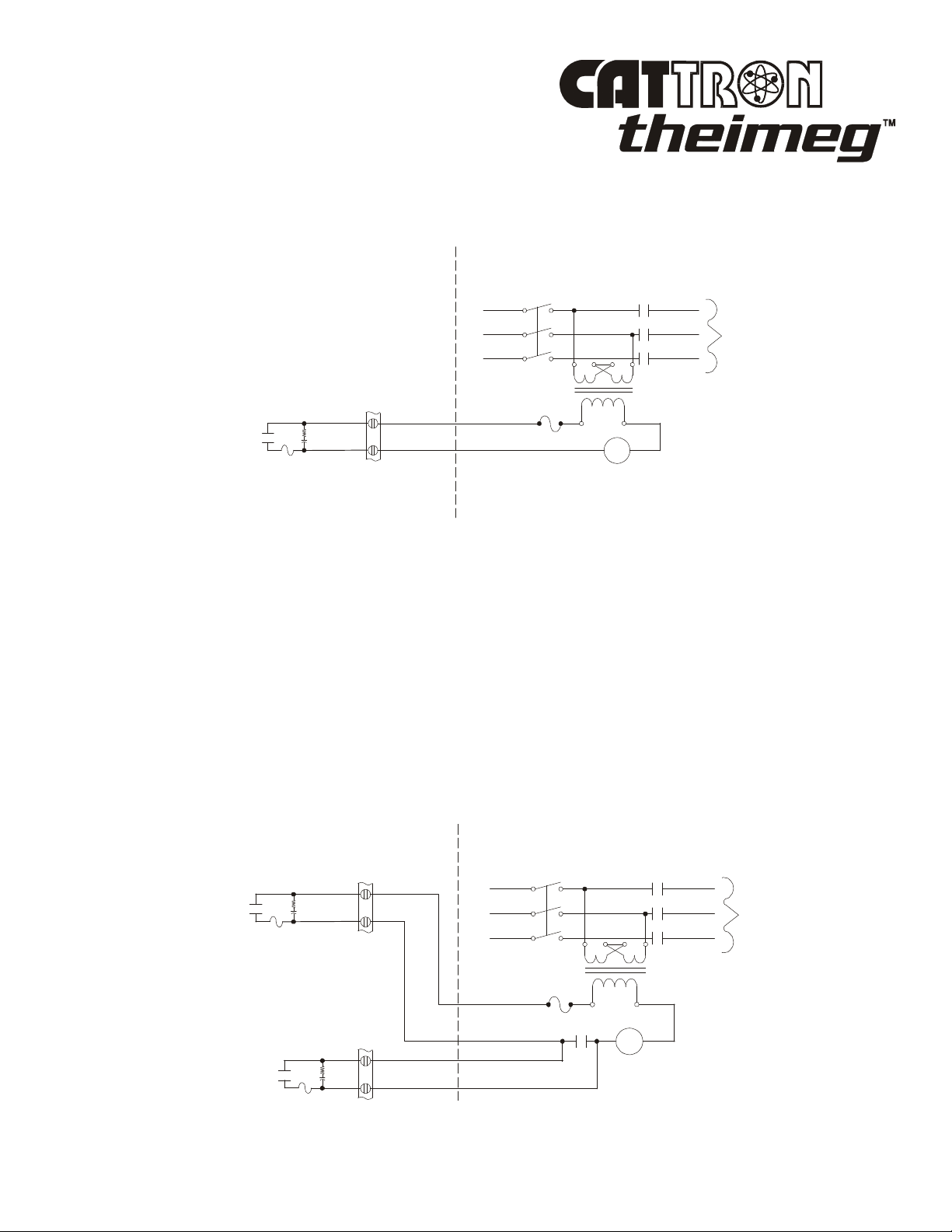
Figure 2-1 opposite shows an Operate (OPR) contact wired directly to the mainline (ML) contactor.
Setting the controller’s Power ON/OFF Switch to ‘ON’ will energize the mainline contactor.
An auxiliary function may be used as a Reset (RST) output that will only be effective when the Operate
(OPR) relay has been closed. Momentary closure of the Reset (RST) relay picks up the mainline (ML)
contactor, which is maintained under control of the OPR. Thus, power is supplied to the controlled
device. If OPR opens, the mainline contactor releases, removing power from the controlled device and
stopping all motion.
Section 2, Page 2 ©10/2002, CATTRON-THEIMEG™
Typical method of operation (continued).
LL1
LL2
LL3
MOTOR
EXISTING CONTROLS
120V
MANUAL
DISCONNECT
LL1
LL2
LL3
MOTOR
RECEIVER/DECODER
EXISTING CONTROLS
Figure 2-1. Operate (OPR) contact wiring
MANUAL
DISCONNECT
ML
L1
L2
L3
TO
OPR
R
C
5.0A
120V
ML
RECEIVER/DECODER
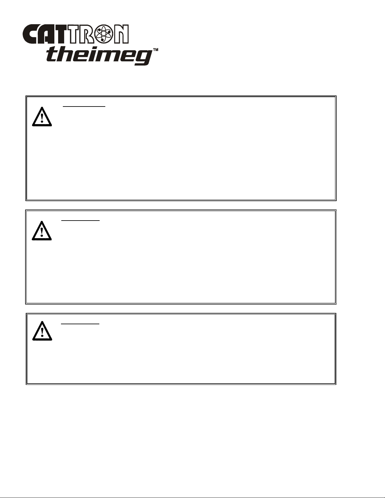
Figure 2-2 below shows the Operate (OPR) relay and optional Reset (RST) relay wired to control a
mainline (ML) contactor. This configuration requires the operator to activate the reset function on the
controller after he/she has turned the unit on. Once reset, the ML contactor stays energized until OPR
de-energizes.
In addition to being energized by the presence of a signal from the controller, OPR is under supervision
of the Automatic Safety Override (ASO) circuit. The ASO circuit disables the OPR (shutting down the
controlled machinery) if a directional output relay is active when no corresponding command is being
received from the controller. In this event, no action is required by the operator to stop the equipment.
The ASO safety circuitry will stop motion automatically without any operator command when a
directional output relay fault is detected.
Figure 2-2. Operate (OPR) contactor and Reset Relay (RST) wiring
ML
TO
OPR
R
C
5.0A
L1
L2
L3
RST
R
C
5.0A
©10/2002, CATTRON-THEIMEG™ Section 2, Page 3
ML
ML
Radio Control Operator’s Duties – General Equipment.
WARNINGS:
WITH THE EXCEPTION OF LOCOMOTIVES, ALL EQUIPMENT MUST
HAVE A MAINLINE (ML) CONTACTOR INSTALLED AND ALL
TRACKED EQUIPMENT (i.e. CRANES) HAVE A BRAKE INSTALLED.
THE REMOTE CONTROL OPERATE (OPR) RELAY MUST BE
CONNECTED TO THE MAINLINE SO THAT STOP COMMANDS OR
FAULT CONDITIONS MONITORED BY AUTOMATIC SAFETY
OVERRIDE (ASO) CIRCUITRY WILL DE-ENERGIZE THE MAINLINE
CONTACTOR AND SET THE EQUIPMENT BRAKE.
FAILURE TO COMPLY WITH THE ABOVE WARNINGS MAY RESULT IN
SERIOUS INJURY OR DEATH TO PERSONNEL AND DAMAGE TO
EQUIPMENT.
WARNING:
MORE THAN ONE REMOTE CONTROL SYSTEM MAY BE USED AT,
AROUND, OR NEARBY YOUR OPERATING FACILITY. THEREFORE,
YOU MUST INSURE THE ADDRESS CODE AND FREQUENCY OF YOUR
PADDLE CONTROLLER EXACTLY MATCHES THE ADDRESS CODE AND
FREQUENCY OF THE DESIRED EQUIPMENT TO BE OPERATED.
FAILURE TO COMPLY WITH THE ABOVE WARNING MAY RESULT IN
THE UNDESIRED OPERATION OF OTHER EQUIPMENT WHICH, IN
TURN, COULD RESULT IN SERIOUS INJURY OR DEATH TO
PERSONNEL AND DAMAGE TO EQUIPMENT.
Section 2, Page 4 ©10/2002, CATTRON-THEIMEG™
WARNING:
ON CAB AND REMOTE OPERATED CRANES OR CARRIERS AN AUDIBLE
OR VISUAL WARNING MEANS SHALL BE PROVIDED. IN ADDITION,
ALL EQUIPMENT SHALL HAVE AUDIO OR VISUAL ALARM
INDICATIONS MEETING GOVERNMENTAL REQUIREMENTS. FAILURE
TO IMPLEMENT THIS WARNING MAY RESULT IN SERIOUS INJURY OR
DEATH TO PERSONNEL AND DAMAGE TO EQUIPMENT.
Radio Control Operator’s Duties – General Equipment, continued.
WARNING PER FCC Part 15.21:
Changes or modifications not expressly approved by the manufacture could void the user's
authority to operate the equipment.
WARNING:
DUE TO FCC PART 15 AND DOC RSS-210 RADIO TRANSMIT
REGULATIONS, THE OPR OUTPUT TO WHICH YOUR CONTROLLED
EQUIPMENT’S MAINLINE CONTACTOR IS CONNECTED WILL REMAIN
ENERGIZED FOR TEN MINUTES AFTER THE CONTROLLER POWER IS
SET TO ‘OFF’, OR FOR TEN MINUTES AFTER THE LAST TIME A
FUNCTION SWITCH IS ACTIVATED. CONSEQUENTLY, SPECIAL CARE
MUST BE TAKEN IF THE CRANE OR TRACKED MACHINE IS EQUIPPED
WITH A PARKING BRAKE THAT IS CONFIGURED TO ENGAGE WHEN
THE MAINLINE CONTACTOR DE-ENERGIZES.
TO PREVENT A POTENTIALLY HAZARDOUS SITUATION, YOU SHOULD
IMMEDIATELY SELECT THE RED ‘STOP’ FUNCTION ON YOUR REMOTE
CONTROLLER AFTER COMPLETION OF OPERATIONS. SUCH ACTION
WILL INSURE THE PARKING BRAKE (IF EQUIPPED AND CONFIGURED
AS ABOVE) IS SET, PREVENTING UNINTENTIONAL MOVEMENT OF THE
CRANE OR TRACKED MACHINE.
FAILURE TO COMPLY WITH THIS WARNING MAY RESULT IN SERIOUS
INJURY OR DEATH TO PERSONNEL AND DAMAGE TO EQUIPMENT.
WARNING:
NEVER DISABLE THE PUSH TO OPERATE (PTO) BAR SWITCH ON YOUR
REMOTE CONTROLLER. FAILURE TO COMPLY WITH THIS WARNING
MAY RESULT IN DAMAGE TO EQUIPMENT, SERIOUS INJURY, OR
DEATH.
©10/2002, CATTRON-THEIMEG™ Section 2, Page 5

Radio Control Operator’s Duties – General Equipment, continued.
The following procedures provide general guidelines for radio control operation of equipment and
should not be used as a substitute for your plant operating procedures.
1. Before operating equipment, carry out the following:
a. Insure the address code and frequency of your paddle controller exactly matches the
address code and frequency of the target equipment to be operated.
The address and frequency assigned to your controller is recorded (1) on the front page of
this manual, and (2) on a serial tag located inside the battery door. The address and
frequency of the target receiver/decoder is recorded (1) on the front page of the manual
supplied with the portable remote control system, and (2) on a label located inside the
receiver/decoder.
If a controller having the wrong address code and frequency is selected, the target
equipment will not operate. However, other equipment located at, around, or nearby your
facility may become operational.
Notes: If you are not familiar with the controls and indicators on your
controller, please refer to ‘Controls and Indicators’ in Section 3 of
this manual and the operational description provided with your
controller.
Some controllers have two power ON/OFF switches (a Keyswitch
and a Toggle switch). Both of these switches must be set to ‘ON’
for power to be applied to the controller.
b. Set the controller’s Power ON/OFF Switch(es) to the ‘ON’ position. When transmitting
with a good battery, two short ‘beeps’ will be heard immediately after the Power
ON/OFF Switch is set to ‘ON’ and a green TRANSMIT LED will ‘flash’ rhythmically.
When the battery starts to go low, the green LED changes to a red LOW BATTERY
LED which ‘flashes’ continuously. This means you should change or re-charge the
battery pack as soon as possible - refer to Battery Packs and Battery Pack Charging in
Section 3 of this manual.
c. When installed, depress the ALARM/RESET push button switch located in the center of
the PTO bar (this is normally an optional function that sounds the equipment alarm or
horn and resets the main power contactor).
d. Check each function independently to be sure that equipment is responding correctly.
e. Where a limit switch is provided, you should check the limit switch at the beginning of
each shift as defined by your plant operating procedures.
f. Check Range Limiting if used – refer to Appendix ‘A’ of the manual supplied with your
PRC system.
g. Check STOP operation
h. Check brake operation.
Section 2, Page 6 ©10/2002, CATTRON-THEIMEG™

Radio Control Operator’s Duties – General Equipment, continued.
2. You must report all defective or missing safety equipment, mechanical or electrical defects to
your supervisor without delay. Do not continue operation until fully repaired.
3. If anyone is in the path of equipment travel, stop and sound the alarm before proceeding. Do not
proceed until the pathway is clear
4. Persons operating this equipment shall not use a limit stop as a utility stopping device.
5. When leaving the equipment area for any reason, set the controller’s Power ON/OFF Switch(es)
to the ‘OFF’ position. If a Key Switch is installed, remove the key from the controller and keep
it on your person.
6. Do not allow any unauthorized person to operate the controller.
7. Do not operate the controller at a distance where the equipment and all surrounding objects are
not visible.
8. Do not attempt to override any of the safety features built into the Radio Control System.
9. If, for any reason, you or anyone has to board the radio controlled equipment, set the controller’s
Power ON/OFF Switch(es) to the ‘OFF’ position. If a Key Switch is installed, remove the key
from the controller and keep it on your person.
©10/2002, CATTRON-THEIMEG™ Section 2, Page 7

Radio Control Operator’s Duties – Electrical Overhead
Traveling (EOT) Crane.
WARNINGS:
ALL EQUIPMENT MUST HAVE A MAINLINE (ML) CONTACTOR
INSTALLED AND ALL TRACKED EQUIPMENT (i.e. CRANES) HAVE A
BRAKE INSTALLED.
THE REMOTE CONTROL OPERATE (OPR) RELAY MUST BE
CONNECTED TO THE MAINLINE SO THAT STOP COMMANDS OR
FAULT CONDITIONS MONITORED BY AUTOMATIC SAFETY OVERRIDE
(ASO) CIRCUITRY WILL DE-ENERGIZE THE MAINLINE CONTACTOR
AND SET THE EQUIPMENT BRAKE.
FAILURE TO COMPLY WITH THE ABOVE WARNINGS MAY RESULT IN
SERIOUS INJURY OR DEATH TO PERSONNEL AND DAMAGE TO
EQUIPMENT.
WARNING:
MORE THAN ONE REMOTE CONTROL SYSTEM MAY BE USED AT,
AROUND, OR NEARBY YOUR OPERATING FACILITY. THEREFORE,
YOU MUST INSURE THE ADDRESS CODE AND FREQUENCY OF YOUR
PADDLE CONTROLLER EXACTLY MATCHES THE ADDRESS CODE AND
FREQUENCY OF THE DESIRED EQUIPMENT TO BE OPERATED.
FAILURE TO COMPLY WITH THE ABOVE WARNING MAY RESULT IN
THE UNDESIRED OPERATION OF OTHER EQUIPMENT WHICH, IN
TURN, COULD RESULT IN SERIOUS INJURY OR DEATH TO PERSONNEL
AND DAMAGE TO EQUIPMENT.
Section 2, Page 8 ©10/2002, CATTRON-THEIMEG™
WARNING:
ON CAB AND REMOTE OPERATED CRANES OR CARRIERS AN AUDIBLE
OR VISUAL WARNING MEANS SHALL BE PROVIDED. IN ADDITION, ALL
EQUIPMENT SHALL HAVE AUDIO OR VISUAL ALARM INDICATIONS
MEETING GOVERNMENTAL REQUIREMENTS. FAILURE TO
IMPLEMENT THIS WARNING MAY RESULT IN SERIOUS INJURY OR
DEATH TO PERSONNEL AND DAMAGE TO EQUIPMENT.
 Loading...