

Cattron North America 810A User Manual
!
WARNING
Read all safety rules and warnings before installing and operating this system.
Smart Technology. Delivered.
Command Pro
Engineered Systems
User Manual

Command Pro Engineered Systems
Revision
Date
Changes
1.0 Initial Release
2.0
04/2014
Updated Styles
Revised Content
2.1
06/2014
Updated Mounting Hole Dimensions for 21R14A
Updated Warning Style
User Manual
REVISION HISTORY
2 142134

Command Pro Engineered Systems
User Manual
TABLE OF CONTENTS
Revision History .......................................................................................................................... 2
Table of Contents ........................................................................................................................ 3
1 Important Safety Notice ....................................................................................................... 4
2 Compliance Statement ......................................................................................................... 5
3 Safety Rules ......................................................................................................................... 6
3.1 Personal Safety ................................................................................................................................................... 6
3.2 Care ........................................................................................................................................................................ 6
4 Introduction ......................................................................................................................... 7
4.1 Purpose ................................................................................................................................................................. 7
4.2 Scope ..................................................................................................................................................................... 7
4.3 Important Safety Rules ..................................................................................................................................... 7
4.4 Carrying Strap for ‘Belly Box’ Controllers .................................................................................................. 7
5 Operations ......................................................................................................................... 10
5.1 How the System Works.................................................................................................................................. 10
5.2 Transmitter Operation and Features ......................................................................................................... 12
5.3 Wireless Operation .......................................................................................................................................... 12
5.4 Pendant Operation .......................................................................................................................................... 12
5.5 Commands ......................................................................................................................................................... 12
5.6 Status Indicators ............................................................................................................................................... 14
6 Installation......................................................................................................................... 15
6.1 General ................................................................................................................................................................ 15
6.2 Locating the Equipment ................................................................................................................................ 15
6.3 Installation Wiring ............................................................................................................................................ 17
6.4 Installation Procedure -21R14A Receiver ................................................................................................. 17
6.5 Installation Procedure -21R22...................................................................................................................... 21
6.6 Installation Procedure – SAFE-T-RANGE (21R22CR) ............................................................................ 25
6.7 Installation Procedure – 22R08A ................................................................................................................ 27
7 Maintenance & Troubleshooting ........................................................................................ 32
7.1 Monthly Inspection ......................................................................................................................................... 32
7.2 Installation Troubleshooting ........................................................................................................................ 32
7.3 Transmitter Troubleshooting ....................................................................................................................... 32
7.4 Transmitter Spare Parts List.......................................................................................................................... 36
7.5 Receiver Troubleshooting ............................................................................................................................. 37
7.6 Receiver Testing ............................................................................................................................................... 37
7.7 Receiver Spare Parts List ............................................................................................................................... 39
8 Warranty Statement for Command Pro 21 and 22 Series .................................................... 40
8.1 Transmitters .......................................................................................................................................................40
8.2 Receivers and Accessories ............................................................................................................................40
8.3 General Terms of Warranty ..........................................................................................................................40
8.4 Service..................................................................................................................................................................40
Appendix I: Transmitter Specifications ...................................................................................... 41
Certifications 42
Appendix II: Receiver Specifications .......................................................................................... 43
3 142134
Command Pro Engineered Systems
!
WARNING
The use of unapproved components or accessories in the systems sold by Laird and its subsidiaries is
strictly prohibited. Unapproved components are defined as any component not inspected and sold
by Laird. This also includes any component modified from its intended use and/or any component
exhibiting observable damage or defect. Use of non-conforming parts, assemblies and accessories
may lead to injury or death.
!
WARNING
The remote control system you have purchased is designed to stop in a safe mode under a variety of
conditions. Some examples of these conditions are: excessive radio signal interference, loss of battery
or electrical power, failure of certain components and operation beyond signal range and others.
Although Laird and its subsidiaries does not specify the position of the operator when controlling the
equipment we are aware that some users are instructed and trained by their employer to ride the
equipment in a safe manner. It is imperative that you are prepared for an unplanned stop of the
equipment at any time and do not place yourself or others in a position where this situation may
cause you to fall from the equipment. Failure to use caution may lead to injury or death.
User Manual
Certifications 44
Support ..................................................................................................................................... 45
1 IMPORTANT SAFETY NOTICE
4 142134

Command Pro Engineered Systems
User Manual
2 COMPLIANCE STATEMENT
COMMAND PRO® series receivers have been tested and found to comply with the limits for a Class B digital
device, pursuant to Part 15 of the FCC Rules. These limits are designed to provide reasonable protection
against harmful interference in a residential installation.
This equipment generates, uses, and can radiate radio-frequency energy, and if not installed and used in
accordance with the user manual, may cause harmful interference to radio communications. However, there
is no guarantee that harmful interference will not occur in a particular installation.
If this equipment does cause harmful interference to radio or television reception, which can be determined
by switching this equipment on and off, the user is encouraged to try to correct the interference by one or
more of the following measures:
Reorient or relocate the receiving antenna connected to the device that is receiving the interference.
Increase the separation between Laird equipment and the equipment receiving the interference.
Consult our factory or one of our Service Representatives for additional help.
FCC Part 15.19 Warning Statement: This device complies with part 15 of the FCC Rules. Operation is subject to
the following two conditions: (1) This device may not cause harmful interference, and (2) this device must
accept any interference received, including interference that may cause undesired operation.
FCC Part 15.21 Warning Statement: The grantee is not responsible for any changes or modifications not
expressly approved by the party responsible for compliance. Such modifications could void the user’s
authority to operate the equipment
IC RSS-GEN, Sec 8.4 Warning Statement- (Required for license-exempt devices)
(ENGLISH) This device complies with Industry Canada license-exempt RSS standard(s). Operation is subject to
the following two conditions: (1) this device may not cause interference, and (2) this device must accept any
interference, including interference that may cause undesired operation of the device.
(FRENCH) Le présent appareil est conforme aux CNR d'Industrie Canada applicables aux appareils radio
exempts de licence. L'exploitation est autorisée aux deux conditions suivantes : (1) l'appareil ne doit pas
produire de brouillage, et (2) l'utilisateur de l'appareil doit accepter tout brouillage radioélectrique subi,
même si le brouillage est susceptible d'en compromettre le fonctionnement.
Responsible Party:
Laird, Inc.
1916 W. Mission Rd.
Escondido, CA 92029
Phone: 800-328-5570
Fax: 760-737-7810
5 142134
Command Pro Engineered Systems
!
WARNING
Read all instructions. Failure to follow these rules can result in serious personal injury.
!
WARNING
Failure to follow these rules can result in serious personal injury.
User Manual
3 SAFETY RULES
GROUND THE RECEIVER CASE. In order to ensure safety of the system, firmly connect the receiver
case to earth ground.
PROVIDE A SAFETY CUTOFF SWITCH. If maintenance is required, disconnect the radio from power to
prevent accidental activation.
USE PROPER WIRING. Loose or frayed wires can cause accidental machinery activation.
DO NOT INSTALL IN HOT AREAS. This apparatus can be damaged by heat in excess of 160° F.
DO NOT INSTALL IN HIGH VIBRATION AREAS. The life of this apparatus might be shortened through
long exposure to intense shaking or vibration.
3.1 Personal Safety
MAKE SURE MACHINERY IS CLEAR BEFORE OPERATING. Do not activate the remote system unless it is
safe to do so.
SWITCH OFF THE RECEIVER POWER BEFORE WORKING ON MACHINERY. Always disconnect the
remote system power before performing any maintenance to prevent accidental machine operation.
3.2 Care
KEEP DRY. If water or other liquids get inside the device, immediately dry the unit.
KEEP ANTENNAS CLEAN. Keep antenna connections clean and free of corrosion.
Note: Throughout this manual, other safety rules appear under the following heading:
6 142134
Command Pro Engineered Systems
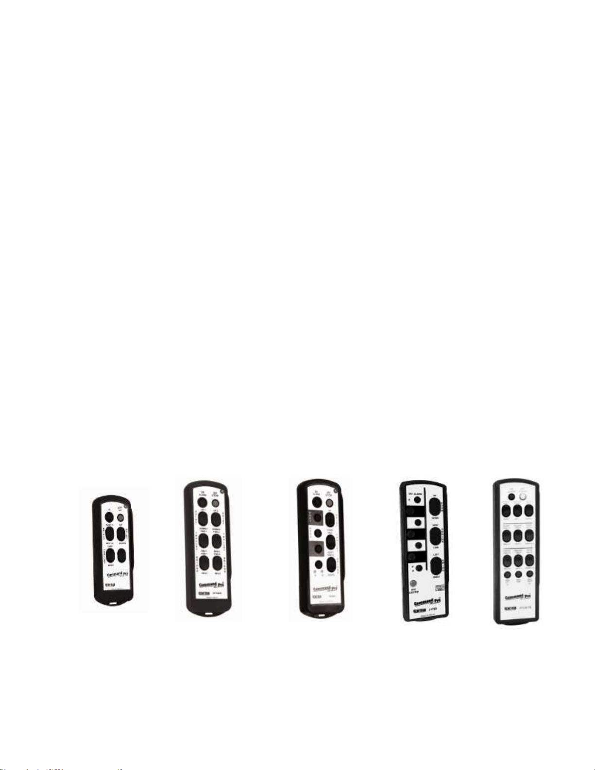
21T10(A)
21T14(A)
21T18(A)
21T20
21T23
User Manual
4 INTRODUCTION
4.1 Purpose
This manual provides information on the safe installation and operation of the Laird Command Pro® wireless
control systems. Information is also included on the maintenance and repair of the Command Pro systems.
4.2 Scope
Information is included on all types of Laird transmitters and receivers used in industrial applications. Refer to
the detailed information contained in each section for your particular equipment.
The transmitters covered in this manual contain enhanced features that expand the types of applications for
the systems.
Many new features have been added, but most changes are transparent to the user. If you are already
familiar with Laird transmitters, you are encouraged to read the section on operating the transmitters, where
there is information about the latest changes in operation.
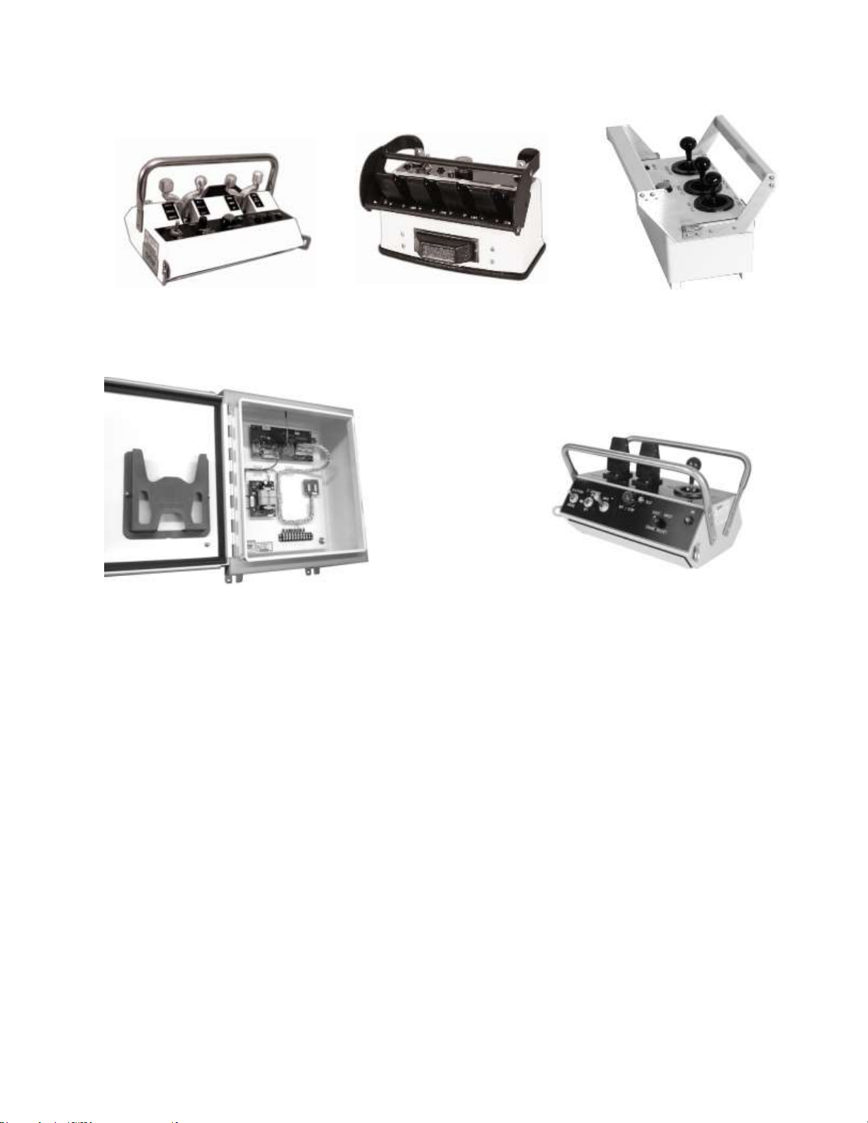
To help you identify your system, Figure 1and Figure 2 provide a reference for the transmitters and receivers
covered in this manual. Review the Configuration Sheet that came with your equipment for details on the
types of switches and the labels used on your equipment.
4.3 Important Safety Rules
Using wireless control systems with heavy industrial equipment can improve the safety of the equipment.
It is important to adhere to the safety rules presented throughout this manual, especially during installation,
in order to achieve the safest operating system possible.
4.4 Carrying Strap for ‘Belly Box’ Controllers
A Shoulder Carrying Strap (Part #600057) is supplied with the 21T34A, T44A, T54A, and T74A ‘Belly Box’-style
controllers which greatly enhances operator comfort. Operators of these ‘Belly Box’-style controllers are
required to use this approved carrying strap with the controller attached at all times.
7 142134
Command Pro Engineered Systems
21T34A
Stepped Lever Control
Transmitter
21T44A
Proportional Lever
Control
Transmitter
21T54A
Joystick Control Transmitter
-
T08C
Remotely Operated Transmitter
21T74A
Custom Lever Control Transmitter
User Manual
Figure 1: Laird Command Pro Engineered Systems Transmitters
8 142134
Command Pro Engineered Systems
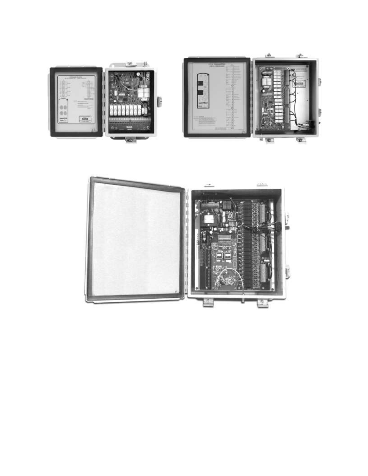
22R08A
8 Function Receiver
21R14A
14 Function Receiver
21R22
22 to 66 Function Receiver
User Manual
Figure 2: Laird Command Pro Engineered Systems Receivers
9 142134

Command Pro Engineered Systems
User Manual
5 OPERATIONS
Laird Command Pro Wireless Control Systems are designed to control industrial machinery. These rugged
controls are built to survive the wear and tear of life in factories, mills, and foundries.
These systems comply with operation requirements under Part 15 of the FCC Rules and Regulations. This
means that neither the operator nor the company need apply or register for a license to operate this
equipment.
The basic system consists of a transmitter and a receiver. The transmitter sends commands to the receiver
through radio waves in the 900 MHz band. Receivers operate at 120 VAC 50/60 Hz power. Operation from
other power sources is also available.
5.1 How the System Works
5.1.1 Frequency
Laird Command Pro equipment operates in the 902 to 928 Megahertz (MHz) frequency band. A wavelength
at our frequency is 12.9 inches.
Like light, 900 MHz radio signals pass through glass and plastics, and reflect off of walls, buildings, and metal
structures. Unlike light, 900 MHz radio signals penetrate all plastics including those opaque in color, as well
as thin-gauge steel, dry wood, dry concrete, plasterboard, fog, and rain. However, the signal will not readily
pass through trees, earth, water, people, aluminium, copper, and some window tints.
5.1.2 Range and Antenna Coverage
Antennas convert radio signals into radio waves, and convert radio waves back into radio signals. They can
send and receive in all directions or in a single direction, depending on their design.
An omnidirectional antenna is like a light bulb, and a directional antenna is like a flashlight. Metal objects
reflect radio waves, just as a mirror next to a light bulb will reflect light. Metal objects near an antenna alter
the intended pattern of an antenna by either shading or reflecting signals.
Our standard antennas are omnidirectional; they ‘see’ equally well in all directions. We have other antennas
that will ‘see’ further in one direction for special applications.
5.1.3 License-Free Channels
The 902 to 928 MHz spectrum accommodates many license-free users and is set aside by the FCC as an ISM
Band (Industrial, Scientific, and Medical). We have the ability to change frequencies in this band and have 81
different channels that we can assign to the transmitter and receiver. The actual frequency is coded into the
receiver and transmitter at the factory but may be changed to one of the other 80 channels in the field if
desired.
Other devices in this band include wireless phones, computer data links, and inventory equipment. As a
condition of using this band, products must accept and handle interference from other users.
The 900 MHz band works well for most users, and not being burdened with licensing regulations is desirable.
The FCC has allowed 50,000 microvolts per meter field strength on this band, which is 250 times higher than
other unlicensed frequencies below the band. This allows our systems to operate very reliably in the presence
of other signals.
10 142134

Command Pro Engineered Systems
User Manual
5.1.4 Command Format
This device uses packet-mode, Frequency Modulation (FM) to carry commands in packet form from our
transmitter to our receiver.
To reduce battery drain, the transmitter transmits for a hundredth of a second, which is long enough to send
one packet to our receiver at a repetition rate of 16 or 4 times per second.
The rate varies: 16 times per second for three times when sending a command and four times per second
when there is no change in commands and the transmitter is still on. Any time a lever or switch activates, we
send all control settings three times at the 16-per-second rate and then return to the slower rate of 4 times
per second.
Our receiver uses the slower rate for maintaining transmitter timing and provides for a maintained link where
one is used. The only exception to this is the ‘STOP’ switch, which transmits at 16 times per second as long as
it is depressed. In addition to lever and switch positions, each packet contains a unique address and CRC
check sum (described in the next section).
5.1.5 Safety
Safety and loss of control prevention are very important issues at Laird. We use a unique identification (ID)
code for each user. There are provisions in our system for 65,535 individual codes.
Each transmission includes a CRC check sum, which is a polynomial created by factoring all of the previous
bits transmitted. Once the receiver receives a valid start command from the transmitter, the receiver tracks
the time of the transmitter and ignores all other transmissions that do not fall within the expected time frame
of the transmitter.
Maintained link systems must receive at least one valid transmission each second in order to allow the
remote controlled equipment to function. The receiver provides a loss-of-signal control output that safely
shuts down the equipment if a loss of signal occurs.
The receiver will not allow equipment restart under its control after a loss of signal until a valid system start
command is received from the transmitter. This prevents an unintended start-up from occurring if the
transmitter returns within range of the receiver and is still operating.
The transmitters also check the position of all controls upon start-up. The transmitter does not issue a start
command if any of the controls are pressed at the time the start command begins. Exceptions for lights,
horn, bell, or other user functions that do not place machinery in motion can be mapped into our control
logic upon request.
FM systems also have a capture effect, where the strongest signal captures the receiver, which rejects the
weaker signal. The operator is seldom more than 300 feet from the controlled machine. Therefore, the
transmitter is the strongest signal present unless other equipment on this band is allowed to operate within
1000 feet of the location of the receiver.
5.1.6 Carrying Strap for ‘Belly Box’ Controllers
A Shoulder Carrying Strap (Part # 600057) is supplied with the 21T34A, 21T44A, 21T54A, and 21T74A ‘Belly
Box’-style controllers which greatly enhances operator comfort. Operators of these ‘Belly Box’-style
controllers are required to use this approved carrying strap with the controller attached at all times.
11 142134

Command Pro Engineered Systems
!
WARNING
Do not operate the system until you are familiar with radio-controlled operation. If you
are not familiar with radio-controlled operation, contact your supervisor before
attempting to use the radio control system.
User Manual
5.2 Transmitter Operation and Features
IMPORTANT: To stop the system in an emergency, press and hold the OFF/STOP button.
Pressing and holding this button stops all functions.
5.3 Wireless Operation
1. If the transmitter the ‘belly box’ type, operators are required to use the supplied Shoulder Carrying
Strap with the controller attached at all times.
2. If the transmitter is equipped with pendant capability, verify that the pendant cable is not attached
before switching on the transmitter.
3. Press and release the ON/ALARM button. Verify that the Status LED starts flashing at a low rate. If
equipped, the Alarm function sounds.
4. Press the required switches to operate the desired function. Note that more than one function may
be controlled at any time.
5. To stop sending any command, release the switch.
6. To switch the transmitter off, press the OFF/STOP button. (Note that the transmitter switches itself
off if no commands send for a predetermined time and if Auto Off is enabled).
7. If equipped with a maintained OFF/STOP switch, the transmitter continues transmitting the
OFF/STOP signal for a preset time after the OFF/STOP switch is pressed to the maintained position.
Resetting the switch immediately switches the transmitter off.
5.4 Pendant Operation
1. Connect the pendant cable to the transmitter and receiver. If the transmitter was ON in the normal
mode, it will stop RF transmissions and send commands only through the pendant cable. The
transmitter will not resume RF transmissions until the pendant cable is removed and the
transmitter is momentarily switched off.
2. The remainder of the operation is the same as the wireless operation described above.
5.5 Commands
5.5.1 Command Switches
The command switches are labeled according to their function.
If two commands that conflict with each other are attempted, in most cases no function results. In the
case of ON/OFF functions, OFF predominates.
If more than one speed command is sent for the same function, the lower speed predominates.
Maintained On or Off functions require separate commands for ON and OFF.
ON/ALARM: This button switches the transmitter on and puts the system in the active mode. It also sends
an ALARM command to the receiver while the switch is depressed. The transmitter remains active until the
OFF/STOP button is pressed or the transmitter switches itself off (see Auto Off).
12 142134

Command Pro Engineered Systems
User Manual
OFF/STOP: While depressed, this button sends a STOP command to the receiver. The transmitter does
not need to be actively ‘ON’ to send this command. When this switch is released, the transmitter switches
off.
AUTO OFF: The transmitter switches itself off if no commands are sent for a predetermined time.
Normally this time is set to 15 minutes, but it may be programmed from 0 to 60 minutes, or disabled using a
RAC16 Series Programmer (01 to 60 = minutes, 00 = disabled).
Levers (21T34A/44A/74A) / Joysticks (21T54A): When in the neutral (center) position, no commands send.
When a paddle moves from the neutral position, a command generates proportional to the amount of
movement (the further the lever is pushed, the faster the movement is commanded).
Push-to-Operate (PTO) Switch (Optional): The PTO or ‘Dead Man Switch’ is a safety device. The
transmitters are normally programmed so that the switch that activates this function must be depressed
before any motor or other critical function can operate (consult the Configuration Sheet if this switch has an
alternate use in your system).
First-Come First-Serve (FCFS) (Optional): The First-Come First-Serve option allows use of multiple
transmitters with one receiver, one at a time. The receiver scans a preset list of ID Codes. When a valid signal
is received, the receiver stops scanning and responds only to that transmitter’s signal. When the signal is no
longer being received (that is, the transmitter has been switched off or is out of range), the receiver again
scans until another valid signal is received.
Pitch-and-Catch (Optional): Pitch-and-Catch is similar to First-Come First-Serve but adds the safety
requirement that the operator in control must release or ‘pitch’ the control before another operator may
assume control. It also allows control transfer from one operator to another without pausing operation. Once
the transmitter has taken control of the receiver, the pitch button is the only way to release control of the
receiver so that other transmitters can take control. Once the receiver receives a valid pitch command, the
receiver then looks for the next programmed ID code. A Catch is made when the ID code from the next
transmitter is recognized. If a catch is not made within a pre-set time period, the receiver will revert to FirstCome First-Serve until a valid ID code is recognized. Any switch can be programmed as the pitch button.
Note: If a transmitter malfunctions after the receiver has taken control, the only way to release the
receiver is to cycle power to the receiver.
A- B Switch (Optional): Selector switches can be provided to control more than one similar function with
the same controls (i.e. controlling trolley/hoist A, trolley/hoist B, or both A and B simultaneously). On the
handheld transmitters, a single pushbutton cycles between A, B, Both, and OFF each time the button is
pressed. LED indicators show the control status.
Key Switch (Optional): The key switch option can prevent the use of the transmitter by unauthorized
personnel. The key switch is electrically connected between the battery and the electronics so that all power
is removed when the switch is in the OFF position.
Note: Once power is applied, the red LED illuminates and the transmitter performs a self-test procedure
lasting approximately three seconds. The transmitter may be switched to ‘ON’. Under standard
operating conditions, the LED flashes green once when the transmitter switches to ‘ON’.
Magnet Control (Optional): An additional safety feature is built into systems that use a lifting magnet.
The two-button design uses one button labeled MAG LIFT (or LIFT) and one button labeled MAG DROP (or
DROP). Pressing the LIFT button energizes the magnet. Pressing LIFT and DROP at the same time deenergizes the magnet and drops the load.
A time-delay is built into the circuit, so the buttons must be held for nearly one second before the magnetic
controls activate. An additional switch may be provided for fanning or dribbling the load. Pressing the button
labeled FAN or MAG FAN while pressing MAG LIFT activates the fan drop function. Again, a time-delay is
built into the circuit, so these buttons must be held down for nearly one second before the magnetic controls
activate.
13 142134

Command Pro Engineered Systems
LED Indication
Possible Cause
LED is off.
Transmitter is off – switch transmitter ON.
Batteries are dead – replace batteries.
Transmitter failure – call for service.
LED flashes at low rate.
Transmitter is operating in a normal mode.
LED flashes at high rate.
Command Switch is pressed.
LED flashes Red/Green (‘A’
series only).
Batteries getting low. Change batteries at the next
convenient opportunity.
LED flashes on-off at a slow
rate (½ second on and ½
second off).
Batteries getting low. Change batteries at the next
convenient opportunity.
LED remains on
continuously (LED might
flicker slightly).
A switch was activated at the time the transmitter was
switched on, or a general failure occurred that requires
factory service. Ensure no other switches are pressed
while attempting to switch the transmitter on.
LED will not light when
ON/OFF button is pushed.
Replace batteries. If this does not correct the problem, the
transmitter must be repaired.
User Manual
Multiple Receivers Controlled by Multiple Transmitters Option: One transmitter can control a maximum
of six receivers with a rotary selector switch. A rotary switch is often used to select a particular hoist/trolley
A/both/B. It can also be used for crane select, i.e. East/West.
5.6 Status Indicators
5.6.1 Status LED
The status LED indicates the transmitter operation. When the transmitter is operating normally, the LED
indicator emits short flashes at a low rate when no commands activate, and at a higher rate when a
command activates. Some transmitters use a red LED only. Others use a multicolored LED that flashes GREEN
when no problems are present and changes to RED when problems are encountered. See Status Chart
below.
Table 1: Transmitter Status Chart
5.6.2 Function Select LEDs
Two LEDs are used on some transmitters to indicate which control functions are active (such as hoist trolley A
or hoist trolley B. These are commonly used with pilot relays). When both are illuminated, both controls are
active. When both LEDs go out, neither control is active.
14 142134
 Loading...