

Cattron North America 79545 User Manual

Product Development
LAIRD
LRM Radio Module – Host Interface Specification
900MHz User Manual
Document p/n: 9S02-7954-A501 Rev. A
CONFIDENTIALITY NOTICE
This correspondence and all information contained within are the exclusive, confidential and proprietary
property of Laird. it is not to be reproduced, nor is it or any portion of it to be used by or disclosed to any
other individual or legal entity, without the prior, written approval of Laird. Furthermore, the information
contained within this correspondence is also to be handled in accordance with any and all confidentiality
agreements between Laird and the receiver or user of this information.
.
2015 LAIRD
LRM Radio Module – Host
Date
Revision
Description
Signature / Date
2010-10-06
EM1
Initial draft
Prepared
Pierre Montreuil
Verified
Approved
2010-10-06
EM2
General revision.
Removed LQI measurement
Updated the configuration section (section 5)
Prepared
Pierre Montreuil
Verified
Approved
2015-11-10
A
Fig 4.8 and 4.9 - Remove remaining references to LQI from
drawings.
Table 4.2 – Rename ESC_END for ESC_SOF
[LaB] Added demodulated analog output on pin 48 and
GND on pin 50
Prepared
Pierre Montreuil
Verified
Approved
Prepared
Verified
Approved
Document p/n: 9S02-7954-A501 Rev. A
Interface Specification
LAIRD
Revision History
2015 LAIRD Proprietary and Confidential Page ii

LRM Radio Module – Host
Document p/n: 9S02-7954-A501 Rev. A
Interface Specification
LAIRD
Table of Contents
1. INTRODUCTION ........................................................................................................................................... 1-1
1.1 PURPOSE ..........................................................................................................................................................1-1
1.2 SCOPE ..............................................................................................................................................................1-1
1.3 APPLICABILITY ................................................................................................................................................1-1
1.4 DEFINITIONS, ACRONYMS ................................................................................................................................1-1
1.4.1 Definitions ..............................................................................................................................................1-1
1.4.2 Acronyms ................................................................................................................................................1-1
2. FEATURES SUMMARY ................................................................................................................................ 2-1
3. HOST INTERFACE DEFINITION ............................................................................................................... 3-2
3.1 PINS ASSIGNMENT ...........................................................................................................................................3-2
3.2 SIGNALS DESCRIPTION .....................................................................................................................................3-3
4. LRM CONFIGURATION CONCEPT .......................................................................................................... 4-4
4.1 I2C ..................................................................................................................................................................4-4
4.2 SPI ..................................................................................................................................................................4-4
4.3 CONSOLE INTERFACE.......................................................................................................................................4-4
4.3.1 “Write” command ................................ ................................ ................................................................ ...4-4
4.3.2 “Read” command ....................................................................................................................................4-5
4.3.3 “Help” command ....................................................................................................................................4-5
4.4 STAND-ALONE TEST MODE .............................................................................................................................4-5
4.5 FIRMWARE DOWNLOAD ...................................................................................................................................4-6
5. REGISTERS MAP SUMMARY .................................................................................................................... 5-7
5.1 REGISTERS DESCRIPTION FIELDS ......................................................................................................................5-7
6. REGISTERS .................................................................................................................................................... 6-8
6.1 SECTION 1 REGISTERS: HARDWARE INFORMATION BLOCK ..............................................................................6-8
6.1.1 HW Part Number ....................................................................................................................................6-8
6.1.2 HW Revision ..........................................................................................................................................6-8
6.1.3 Serial Number .........................................................................................................................................6-8
6.1.4 Default Operation mode ..........................................................................................................................6-8
6.2 SECTION 2 REGISTERS: SOFTWARE INFORMATION BLOCK ...............................................................................6-8
6.2.1 SW Part Number .....................................................................................................................................6-9
6.2.2 SW Revision ...........................................................................................................................................6-9
6.2.3 Register Map Version number ................................................................................................................6-9
6.3 SECTION 5 REGISTERS: RF INTERFACE CONFIGURATION .................................................................................6-9
6.4 SECTION 7 REGISTERS: TEST COMMANDS AND PARAMETERS.........................................................................6-10
7. TEST-SPECIFIC PARAMETERS .............................................................................................................. 7-11
2015 LAIRD Proprietary and Confidential Page iii
LRM Radio Module – Host
Document p/n: 9S02-7954-A501 Rev. A
Interface Specification
LAIRD
79545 TRX Module meets Part 15 of the FCC rules and regulations. Compliance with the labeling
requirements, FCC notices is required. In order to comply with FCC Certification requirements, the
Original Equipment Manufacturer (OEM) must fulfill the following requirements.
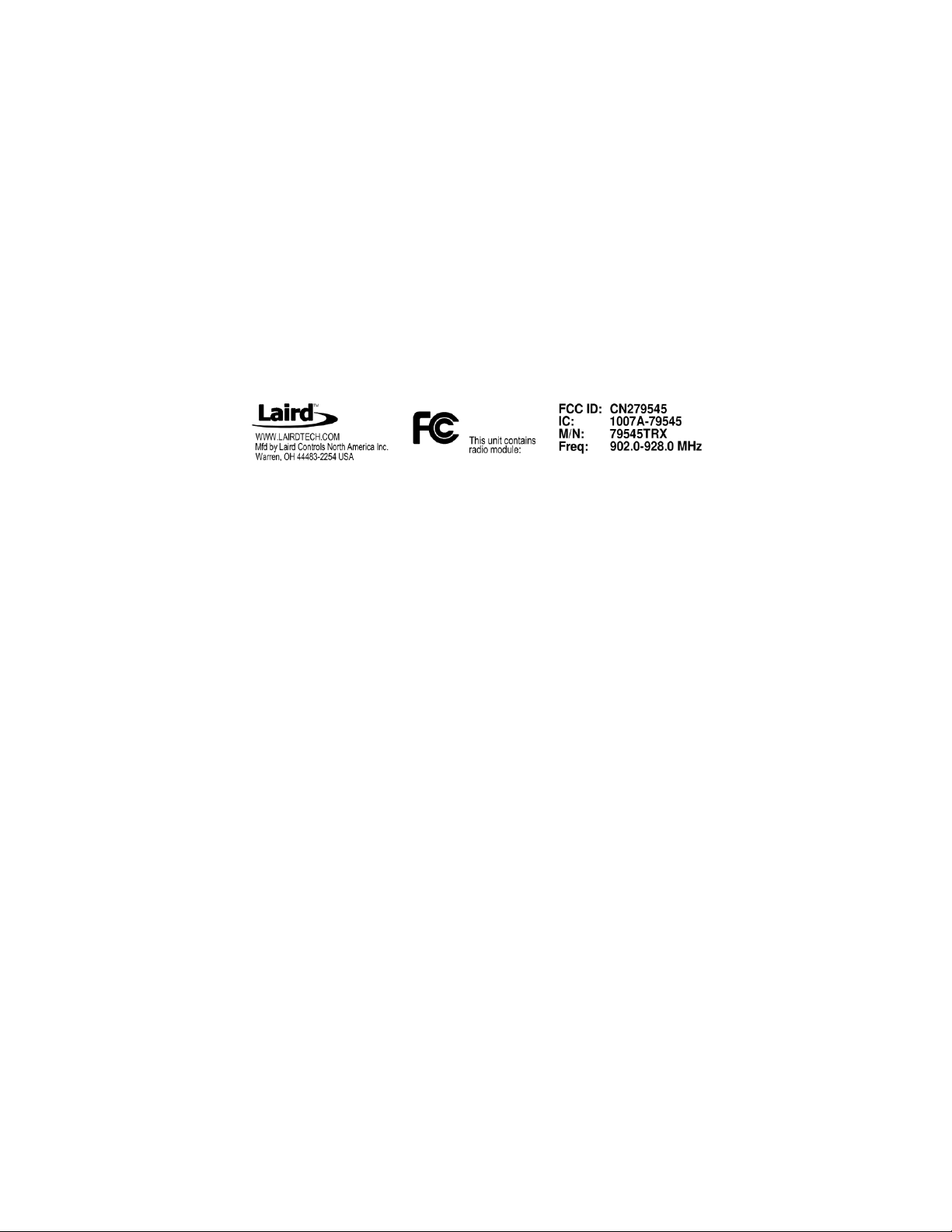
1. The system integrator must place an exterior label on the outside of the final product
housing the 79545 TRX Module. The figure below shows the contents that must be included
in this label.
2. 79545 TRX Module may only be used with the antennas that have been tested and
LABEL
approved for use with the module.
The OEM must make sure that FCC labeling requirements are met. This includes a clearly visible
exterior label on the outside of the final product housing that displays the contents shown in
below.
WARNING: The 79545 TRX Module has been tested by the FCC for use with other products without
further certification (as per FCC Section 2.1091). Changes or modifications to this device not expressly
approved by Laird could void the user’s authority to operate the equipment.
NOTICE: OEM’s must verify the final end product complies with unintentional radiators (FCC Section
15.107 and 15.109) before providing a declaration of conformity for their final product to Part 15 of the
FCC Rules.
RF Exposure WARNING: This equipment complies with FCC radiation exposure limits set forth for an
uncontrolled environment. This equipment should be installed and operated with minimum distance 20
cm between the radiator and your body. This transmitter must not be co-located or operating in
conjunction with any other antenna or transmitter.
NOTICE: The preceding statement must be included as a CAUTION statement in OEM product
manuals in order to alert users of FCC RF Exposure compliance.
79545 TRX is designed for use in countless wireless applications requiring long range communications
with low energy consumption. To ensure that the final product complies with the all of the regulatory
requirements for the Modular Grant the following integration instructions should be followed. 79545
TRX is limited to OEM installation ONLY. The OEM integrator is responsible for ensuring that the enduser has no manual instructions to remove or install the module.
2015 LAIRD Proprietary and Confidential Page iv

LRM Radio Module – Host
FCC Part 15.19 Warning Statement
THIS DEVICE COMPLIES WITH PART 15 OF THE FCC RULES. OPERATION IS SUBJECT TO THE FOLLOWING
TWO CONDITIONS: (1) THIS DEVICE MAY NOT CAUSE HARMFUL INTERFERENCE, AND (2) THIS DEVICE
MUST ACCEPT ANY INTERFERENCE RECEIVED, INCLUDING INTERFERENCE THAT MAY CAUSE UNDESIRED
OPERATION.
FCC Part 15.21 Warning Statement
NOTE: THE GRANTEE IS NOT RESPONSIBLE FOR ANY CHANGES OR MODIFICATIONS NOT EXPRESSLY
APPROVED BY THE PARTY RESPONSIBLE FOR COMPLIANCE. SUCH MODIFICATIONS COULD VOID THE
USER’S AUTHORITY TO OPERATE THE EQUIPMENT.
FCC Part 15.105(b) Warning Statement- (ONLY Required for 15.109-JBP devices)
NOTE: This equipment has been tested and found to comply with the limits for a Class B digital device,
pursuant to part 15 of the FCC Rules. These limits are designed to provide reasonable protection against
harmful interference in a residential installation. This equipment generates uses and can radiate radio
frequency energy and, if not installed and used in accordance with the instructions, may cause harmful
interference to radio communications. However, there is no guarantee that interference will not occur in
a particular installation. If this equipment does cause harmful interference to radio or television
reception, which can be determined by turning the equipment off and on, the user is encouraged to try
to correct the interference by one or more of the following measures:
- Reorient or relocate the receiving antenna.
- Increase the separation between the equipment and receiver.
-Connect the equipment into an outlet on a circuit different from that to which the receiver is connected.
-Consult the dealer or an experienced radio/TV technician for help.
IC RSS-GEN, Sec 7.1.3 Warning Statement- (Required for license-exempt devices)
ENGLISH:
This device complies with Industry Canada license-exempt RSS standard(s). Operation is subject to the
following two conditions: (1) this device may not cause interference, and (2) this device must accept any
interference, including interference that may cause undesired operation of the device.
FRENCH:
Le présent appareil est conforme aux CNR d'Industrie Canada applicables aux appareils radio exempts de
licence. L'exploitation est autorisée aux deux conditions suivantes : (1) l'appareil ne doit pas produire de
brouillage, et (2) l'utilisateur de l'appareil doit accepter tout brouillage radioélectrique subi, même si le
brouillage est susceptible d'en compromettre le fonctionnement.
IC RSS-GEN, Sec 7.1.2 Warning Statement- (Required for Transmitters)
ENGLISH:
Under Industry Canada regulations, this radio transmitter may only operate using an antenna of a type
and maximum (or lesser) gain approved for the transmitter by Industry Canada. To reduce potential radio
interference to other users, the antenna type and its gain should be so chosen that the equivalent
isotropically radiated power (e.i.r.p.) is not more than that necessary for successful communication.
FRENCH:
Conformément à la réglementation d'Industrie Canada, le présent émetteur radio peut fonctionner avec une
antenne d'un type et d'un gain maximal (ou inférieur) approuvé pour l'émetteur par Industrie Canada. Dans
le but de réduire les risques de brouillage radioélectrique à l'intention des autres utilisateurs, il faut choisir
le type d'antenne et son gain de sorte que la puissance isotrope rayonnée quivalente (p.i.r.e.) ne dépassepas
l'intensité nécessaire à l'établissement d'une communication satisfaisante.
IC RSS-GEN, Sec 7.1.2 Warning Statement-(Required for Transmitters w/ detachable antennas)
ENGLISH:
This radio transmitter (identify the device by certification number, or model number if
Category II) has been approved by Industry Canada to operate with the antenna types listed
below with the maximum permissible gain and required antenna impedance for each antenna type
Document p/n: 9S02-7954-A501 Rev. A
Interface Specification
LAIRD
2015 LAIRD Proprietary and Confidential Page v

LRM Radio Module – Host
indicated. Antenna types not included in this list, having a gain greater than the maximum gain indicated
for that type, are strictly prohibited for use with this device.
FRENCH:
Le présent émetteur radio (identifier le dispositif par son numéro de certification ou son numéro de modèle
s'il fait partie du matériel de catégorie I) a été approuvé par Industrie Canada pour fonctionner avec les
types d'antenne énumérés ci-dessous et ayant un gain admissible maximal et l'impédance requise pour
chaque type d'antenne. Les types d'antenne non inclus dans cette liste, ou dont le gain est supérieur au gain
maximal indiqué, sont strictement interdits pour l'exploitation de l'émetteur.
IC RSS-102, Sec 2.6 Warning Statements
ENGLISH:
The user manual of devices intended for controlled use shall also include information relating to the
operating characteristics of the device; the operating instructions to ensure compliance with SAR and/or
RF field strength limits; information on the installation and operation of accessories to ensure compliance
with SAR and/or RF field strength limits; and contact information where the user can obtain Canadian
information on RF exposure and compliance. Other related information may also be included.
FRENCH:
Le mode d'emploi des appareils destinés à l'utilisation contrôlée doit aussi inclure des informations sur
les caractéristiques de fonctionnement de l'appareil; les instructions de fonctionnement pour assurer la
conformité avec SAR et / ou les limites d'intensité de champ RF; informations sur l'installation et
l'exploitation d'accessoires pour assurer le respect des SAR et / ou les limites d'intensité de champ RF; et
les coordonnées où l'utilisateur peut obtenir des informations sur l'exposition canadienne de
radiofréquences et la conformité. Autres renseignements connexes peuvent également être inclus.
Document p/n: 9S02-7954-A501 Rev. A
Interface Specification
LAIRD
FCC Part 15.203 Warning Statement Only one of the following permanent attached antennas should be
used with the module in the final product.
PRT-0000196, 5/8 WAVE COLLINEAR, 50Ohm, 3DB, 896-970 MHZ
485026, ANTENNA, TNC, 1/4 WAVE, 900 MHZ, WHIP, 50 Ohm, 0dBi
2PCA-8339-B501, SPLATCH ANTENNA, 902-928MHZ, 50 Ohm, -5.0dBi
2PCA-7675-B102, UNITY-M ANTENNA BOARD, 915MHZ, 50 Ohm, -5.0dBi
2PCA-7602-E001, MKU PCB Loop Antenna, 50Ohm, -5.0dBi
2OPT-8291-A001, Wire antenna 50Ohm, -6dBi
2PCA-8668-A501, Dipole ANTENNA BOARD, 902-928MHZ, 50 Ohm, 1.75dBi
2PCA-8669-A501, PCB Dipole antenna, 902-928MHZ, 50 Ohm, 1.75dBi
The final product will be shipped with specific antenna installed/equipped permanently by Laird to the end
user. Any change/replace/modification RF cable or antenna is prohibited and not possible to the end user.
2015 LAIRD Proprietary and Confidential Page vi
 Loading...