

Page 1
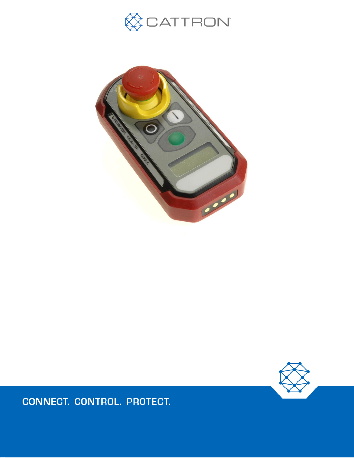
SAFE-E-STOP
™
Personal Safety System
User Guide
9M02-8978-A001-EN
Page 2
2
Version 17
Safe-E-Stop™
User Guide
Revision History
VERSION
DATE
NOTES
13
1/28/2018
Added cautions, updated Fault finding and simplified frequency selection
14
Dec 2018
Updated to include changes made in Safe-E-Stop Version 2 and changed part number
to 9M02-8978-A001 instead of 9M02-8681-A001
15
March 2019
Changed part numbering to reflect country code and added band J plus Black PSDs,
corrected Fig 14
16
05/2019
Document rebranded and contact and DOC information updated
17
7/2019
Added DOC link
Any information furnished by Cattron™ and its agents is believed to be accurate and reliable. All specifications are subject to change without notice.
Responsibility for the use and application
of Cattron products rests with the end user since Cattron and its agents cannot be aware of all potential uses.
Cattron makes no warranties as to non-infringement nor as to the fitness, merchantability, or sustainability of any Cattron products for any
specific or general uses. Cattron Holdings, Inc., or any of its affiliates or agents shall not be liable for incidental
or consequential damages of any
kind. All Cattron products are sold pursuant to the Terms and Conditions of Sale, a copy of which will be furnished upon request. When used as a tradename
herein, Cattron means Cattron Holdings, Inc. or one or more subsidiaries of Cattron Holdings, Inc. Cattron™, corresponding logos, and other
marks are trademarks or registered trademarks of Cattron Holdings, Inc. Other marks may be the property of third parties. Nothing herein provides
a license under any Cattron or any third party intellectual property right.
Page 3

3
Version 17
Safe-E-Stop™
User Guide
Contents
1. Introduction 8
1.1 Terminology 8
2. Warnings and Cautions 9
2.1 MSD wiring 9
2.2 Verification of correct device 9
2.3 Verification of correct linking 9
2.4 Placement of PSD in charger 9
2.5 No serviceable parts 10
2.6 Regulatory Compliance 10
2.7 Awareness of PSD range and Hazards around the machine 10
2.8 The system may cause an unexpected stop of the machine 11
2.9 The safety analysis shall consider the reaction time of the system 11
2.10 Ethernet may not be used for safety-critical function 11
2.11 Frequency Change 11
2.12 Master Address Usage 11
2.13 General Safety Information 11
2.14 Intended Use 12
2.15 Improper Use 12
2.16 Equipment rating warning 13
2.17 Equipment Installation 13
2.18 Configuration Changes 13
3. Operating Principle 14
3.1 General 14
3.2 Radio Transmission 14
3.2.1 Continuous Transmission 14
3.2.2 Radio Interference 14
3.3 Telegram Security 15
3.3.1 System Address 15
3.3.2 CRC 15
3.3.3 Frame Counter 15
4. Frequency Selection 16
4.1 Rules for Frequency selection 16
4.2 Site Planning 17
5. PSD and MSD Configuration Parameters 18
5.1 PSD Configuration 18
Page 4

4
Version 17
Safe-E-Stop™
User Guide
5.2 MSD Configuration 19
2.19 Configuration Part Number 20
PSD Configuration 20
MSD Configuration 20
6. PSD 21
6.1 PSD Overview 21
6.2 PSD Status Indications 21
6.2.1 PSD LEDs 22
6.2.1.1 PSD LCD 22
6.2.1.2 Radio signal level Monitoring 22
6.2.1.3 Battery Monitoring 22
6.2.1.4 General Status Monitoring 23
6.3 Joining an E-Stop Group 23
6.4 Normal Operation 26
6.4.1 Communication Loss 26
6.4.2 Communication Loss Recovery Stage 1 26
6.4.3 Communication Loss Recovery Stage 2 26
6.4.4 Issuing an E-Stop 26
6.4.5 Recovery of an E-Stop 27
6.5 Leaving an E-Stop Group 27
6.6 Switching OFF the PSD 27
6.7 Charging the Battery 27
6.7.1 Battery Capacity and Operating Life 27
6.8 PSD Belt Clip 28
7. Battery Chargers 30
7.1 General Information 30
7.2 Caution 30
7.3 Single Bay Charger 31
7.4 Six-Bay Charger 31
7.5 Battery Charger Status and Indicators 33
8. MSD 34
8.1 MSD Overview 34
8.2 MSD Connections 35
8.2.1 Single Channel Connections Example when using the COMM LOSS Relays 36
8.2.2 Single-Channel Connections Example when not using the COMM LOSS Relays 37
8.2.3 Dual-Channel Connections Example when not using the COMM LOSS Relays 38
8.2.4 Dual-Channel Connection Example using E-Stop relays and the COMM LOSS relays 39
Page 5

5
Version 17
Safe-E-Stop™
User Guide
8.3 MSD Status Indicators 40
MSD LEDs 41
MSD LCD 41
8.4 MSD Operational States 41
8.5 MSD Information and Setup 42
8.6 MSD Ethernet Address Configuration 43
8.6.1 Ethernet Telegram Content 44
8.7 MSD Operation 44
8.8 MSD Installation 44
8.8.1 Safety Instructions for Installation 44
8.8.2 MSD Installation Notes on Enclosure 44
8.8.2.1 MSD Dimensions 45
8.8.2.2 Secondary Enclosure Option Kit (2OPT-8637-A102) Dimensions 46
8.8.3 General Rules for Mounting the MSD 47
8.8.4 MSD Connections 48
8.8.5 MSD Terminals 48
8.8.5.1 Terminal and Wire Specifications 48
8.8.6 Connecting the Antenna 49
9. System Commissioning 50
10. System Decommissioning 51
11. Parts Lists 52
11.1 Part Numbers 52
12. Maintenance 54
12.1 PSD Maintenance 54
12.2 MSD Maintenance 55
12.3 Spare MSD 55
Appendix A: PSD and MSD Configuration 56
A.1 General 56
A.2 Benefits of using the configuration tool 56
Master Address Change 56
A.3 Installing the Configuration Tool 57
A.4 Using the Configuration Tool 58
Appendix B: RF Channel Number vs Operating Frequency 68
Band B (433-434MHz) 68
Band B Channel Spacing Rules 68
Band D (450-470MHz) 68
Band D Channel Spacing Rules 68
Page 6

6
Version 17
Safe-E-Stop™
User Guide
Band F (902-927MHz) 68
Band F Channel Spacing Rules 68
Band J (929MHz) 69
Band J Channel Spacing Rules 69
Appendix C: Approvals and Compliance Notifications 70
FCC Caution 70
EU Caution 70
Equipment Rating 70
Declaration of Conformity 70
Appendix D: Ethernet Configuration & Data Mapping 71
EtherNet/IP 71
Modbus TCP Configuration 74
PROFINET Configuration 76
Electronic Data Sheet (GSD File) 76
Appendix E: Troubleshooting 79
Communication Losses 79
Required Operating Range is Too Long 79
Bad Antenna or Coaxial Cable 79
RF Interference 79
MSD Radio is Faulty 79
PSD 80
Error Light is Flashing 80
Error 1 Shown on LCD 80
Error 2 Shown on LCD 80
Error 3 Shown on LCD 80
Battery Operating Time is Shorter than Expected 80
Cannot Link to MSD 80
MSD Not Seen 80
Operating Range is Short 81
MSD 81
Error Light is Flashing 81
No Power 81
Operating Range is Short 81
Cannot Reset Unit after a PSD Communication Loss 81
Battery Charger 81
Appendix F: Technical Data and Specifications PSD and MSD 82
Appendix G: Technical Data and Specifications Battery Charger 82
7
Page 7

Version 17
Safe-E-Stop™
User Guide
Appendix H: Safety Manual for Safe-E-Stop 83
Functions 83
Failure Modes 83
PSD 83
MSD 83
Operational Constraints 83
Appendix I: Safety Performance Level 85
Page 8
8
Version 17
Safe-E-Stop™
User Guide
1. Introduction
This manual provides guidance to installers and users of the Cattron Safe-E-Stop Personal Safety System.
1.1 Terminology
The following represent important acronyms and long form used in this document:
PSD
Personal Safety Device (the unit worn by a machine operator)
MSD
Machine Safety Device (the unit connected into the hard-wired E-Stop wiring and monitoring
systems)
PSS
Personal Safety System (the entire E-Stop System)
PLC
Programmable Logic Controller
MASTER-ADDRESS
The Primary address used by the system to ensure adjacent systems is unique and will not cross talk
SUB-ADDRESS
The appended address used to identify specific PSDs within a system
COMM LOSS
A loss of RF communication between PSD and MSD
LINKING
Associating a PSD with an MSD and placing into operation as an active E-Stop device
UNLINKING
Disassociating a PSD from an MSD and removing from an active E-Stop group
DIN
Deutsches Institut fur Normung, i.e. German Institute for Standardization.
PL
Performance Level
SIL
System Integrity Level
SC
Systematic Capability
Page 9
9
Version 17
Safe-E-Stop™
User Guide
2. Warnings and Cautions
WARNING and CAUTION statements are strategically placed throughout all text prior to operating or
maintenance procedures, practices, or conditions considered essential to the protection of personnel or
equipment and property. Before starting any task, review and understand the WARNINGS or CAUTIONS included
in the text. All WARNINGS and CAUTIONS appearing in this manual are included below.
WARNING SYMBOL
Meaning: CAUTION
Function: Indicates that caution is necessary relative to the associated content and that the current information
must be followed in order to avoid undesirable consequences.
2.1 MSD wiring
WARNING
The MSD must be hard-wired in series with at least one E-Stop switch so that an E-Stop is still available when
no PSDs are connected.
Failure to comply with the above warning may result in serious injury or death to personnel and damage to
equipment.
2.2 Verification of correct device
WARNING
More than one PSD may be used in, around, or near your machine; therefore, before using any PSD, you must
ensure that the correct unit has been selected and that it matches the machine being protected.by checking the
configuration ID or other means of identification.
If the PSD is not associated with the machine you are using, it may still link to another MSD on an adjacent
machine and may not be providing the protection you are expecting and need.
Failure to comply with the above warnings may result in no protection being provided to stop your machine,
which in turn could result in loss of ability to stop an impending emergency situation and may lead to injury or
death.
2.3 Verification of correct linking
WARNING
After linking the PSD to the machine, there should be a means for the operator to verify the connection; several
methods can be used including color coding, numbering, or using the EtherNet connection with a PLC,
pressing the green button on the PSD, and ensuring the indicator (light or buzzer) on the machine confirms
your connection.
Failure to comply with the above may result in no protection being provided to stop your machine, which in turn
could result in loss of ability to stop an impending emergency situation and may lead to injury or death.
2.4 Placement of PSD in charger
WARNING
Page 10
10
Version 17
Safe-E-Stop™
User Guide
Unlinked PSDs should not be visible to personnel in the area and potentially confused for an available E-Stop
switch. If PSDs in chargers are unlinked, they should not be visible. The easiest way to do this is to place the
charger within a secondary enclosure or position it so that the E-Stop switch faces toward a wall and away from
personnel.
Failure to comply with the above may result in no immediate available protection being provided to stop your
machine, which in turn could result in loss of ability to stop an impending emergency situation and may lead to
injury or death.
2.5 No serviceable parts
WARNING
There are no user serviceable parts in this PSD / MSD system; please return damaged units to Cattron or a
Cattron authorized service center for service and do not attempt to repair these units.
Unauthorized repairs will void the unit’s safety rating and could compromise the unit’s ability to stop your
machine, which in turn could result in loss of ability to stop an impending emergency situation and may lead to
injury or death.
2.6 Regulatory Compliance
WARNING
Observe the statutory regulations and directives applicable for the intended purpose, e.g.:
▪ Accident prevention regulations
▪ Safety rules and directives
▪ Standards
▪ Generally applicable statutory and other binding regulations for accident prevention and environmental
protection, and general safety and health requirements.
2.7 Awareness of PSD range and Hazards around the machine
WARNING
The operators and the personnel in general should be trained to know the operational range limits of the PSD
and the surrounding hazards.
Page 11
11
Version 17
Safe-E-Stop™
User Guide
2.8 The system may cause an unexpected stop of the machine
WARNING
The design of the machine shall consider the risk associated with an unexpected stop of the machine.
2.9 The safety analysis shall consider the reaction time of the system
WARNING
The safety analysis of the application shall consider the reaction time of the system.
2.10 Ethernet may not be used for safety-critical function
WARNING
Ethernet data must only be used for informational purposes. The functionality of the green PSD button that is
available in the Ethernet data should not be used for any safety-critical functionality such as restarting the
machine.
2.11 Frequency Change
WARNING
Selection of the correct operating frequency is entirely the responsibility of the user and Cattron accepts no
responsibility for incorrect frequency selection and configuration.
The frequency selected must strictly conform to channel setting rules shown in section 4 of this manual or the
system may not function correctly.
For licensed frequencies the channel set must also have a valid FCC, IC, or other license, or the user may be
subject to Federal license infringement fines.
Verify correct system operation prior to putting the system into use.
2.12 Master Address Usage
WARNING
Users should ensure that when a system includes one or more spare MSDs, that only one is powered on at a
time or the system will not operate without errors.
All users must ensure that only one Master Address is used in one location, i.e. do not use one MSD and some
associated PSDs in one location and a spare MSD, plus other associated PSDs in another location.
Authorized users must ensure the above is adhered to by associating only one Master Address per user
location.
Verify correct system operation prior to putting the system into use.
2.13 General Safety Information
▪ Persons under the influence of drugs, alcohol and/or other medicine that impairs reaction may not install,
repair, or operate this product.
Page 12

12
Version 17
Safe-E-Stop™
User Guide
▪ All installations must conform to the relevant safety requirements. Only qualified, trained, authorized
personnel may perform work on the equipment, in accordance with the relevant safety requirements.
▪ In the event of malfunction and/or visible defects or irregularities, the operation must be protected by other
PSDs or alternate external means. The PSD/MSD system must be returned to good working order before
being returned once more to operational service.
▪ The operating manual should be permanently accessible at the place of product use.
▪ Personnel assigned to work with the product must have read and understood the operating manual and the
safety instructions.
▪ The safety instructions should be supplemented with work instructions concerning the job organization, work
sequences, qualified personnel, etc.
▪ All repairs made during the warranty period must be carried out by the manufacturer or appointed authorized
service center. Failure to comply will invalidate the warranty.
▪ Only trained personnel may perform maintenance and repair on the product.
▪ All repairs made by these authorized agents should be carried out in a suitably clean, static-safe
environment, free from contaminants such as metal filings, water, oil, etc.
▪ It is the user’s responsibility to ensure that the product is maintained in good condition and that all applicable
safety requirements and regulations are observed.
▪ Product modifications may not be carried out.
▪ Only original spare units from Cattron must be used.
▪ Periodical inspections either required by law or prescribed in this user manual shall be carried out within the
prescribed intervals.
2.14 Intended Use
Only use the product in good condition, by trained personnel, and subject to the compliance with the applicable
operating safety and accident prevention rules and regulations.
2.15 Improper Use
Certain use and work on/with the product are not permitted, in particular:
▪ Deviating from the voltage / frequency data on the type plate
▪ Working on live components
▪ Insufficient maintenance
▪ Failure to observe the operating temperature range
Page 13

13
Version 17
Safe-E-Stop™
User Guide
2.16 Equipment rating warning
CAUTION
Damage of the device
The PSD is rated at IP67 and an operating temperature range of -20°C to +60°C; do not use the PSD for
conditions beyond these limits.
The PSD battery cannot be charged if its temperature exceeds 40°C.
The MSD is rated at IP30 and a temperature range of -20°C to +60°C, up to 90% non-condensing RH; for
environments harsher than this, use an appropriate secondary enclosure.
Exceeding these ratings could compromise the unit’s ability to stop your machine, which in turn could result in
loss of ability to stop an impending emergency situation and may lead to injury or death.
2.17 Equipment Installation
CAUTION
The choice of connection will be determined by the safety level required for the target application and machine.
To achieve SIL3 capable safety levels, a dual channel connection approach will be required and is
recommended, but single channels are optional for lower safety levels and are also illustrated.
Additionally, it must be remembered that the Ethernet port is not safety-critical, only informational, therefore the
functionality of the green button on the PSD should not be used for safety-critical functionality such as
restarting the machine.
Use of the green button for safety-critical functions could result in unexpected actuation of function and may
lead to injury or death.
2.18 Configuration Changes
WARNING
Users should ensure that whenever a configuration change is made or an additional PSD or MSD is configured
for a system, that the system is tested thoroughly for correct operation before being put into operation.
Page 14

14
Version 17
Safe-E-Stop™
User Guide
3. Operating Principle
3.1 General
The MSD has two safety relays that are wired in series with an external hard-wired E-Stop circuit that provides a
machine with the ability to run. The MSD safety relays are changeover types that are held energized in normal
(non-e-stop/run) operation. If the MSD power were removed, the relays would revert to their unpowered state and
the machine would be brought to a halt as though an E-Stop had been pressed.
The MSD is a complex safety PLC. In the event of any fault it will de-energize its safety relays; in its normal
operating mode, it will maintain these safety relays in an energized state.
A normal operating mode can be maintained in the absence of any online PSD, as well as with one or more PSDs
in a linked and normal operating state.
PSDs can come and go as required without affecting the MSD E-Stop safety relays, provided that the PSDs join
and leave the system by the deliberate act and process of linking and leaving the active group. (Patent Pending)
When a PSD is part of the active group, it will trigger an E-Stop if it has its E-Stop switch pressed or if it loses the
RF link to the MSD either because a) it goes out of range, b) it shuts down due to low battery, c) it has a fault, or
d) it has its RF link blocked by interference.
Both the MSD and PSDs feature fully redundant hardware and safety-critical software. They individually and
jointly meet the safety level of SIL3 according to ISO61508.
The MSD polls the PSDs in turn and assigns a PSD an active slot if one is available. The linked PSDs return the
poll after each MSD poll, forming a closed loop safety system.
3.2 Radio Transmission
The connection between the MSD and PSDs is performed by means of radio communication. With regard to the
actual radio frequency that is used, there are several radio frequency bands available.
A specific RF frequency band and channel is selected prior to delivery of the system.
Depending on the frequency band, a defined number of RF channels are available.
The MSD and PSDs must operate on the same RF channel in order to be able to communicate.
Some systems use two RF channels in a frequency diversity mode to increase immunity to RF interference.
3.2.1 Continuous Transmission
Once the units are linked, transmission between MSD and PSD must be continuous. The MSD uses this as part
of the information required to maintain its E-Stop safety relays in a closed state. If the MSD does not receive a
valid telegram from a linked PSD after a short time, it turns off the E-Stop safety relays.
In order to ensure optimum communication between the MSD and PSD, operate the PSD with line-of-sight to the
MSD antenna as far as possible. Avoid total shielding of the signal path by extensive metal and other thick solid
obstructions.
3.2.2 Radio Interference
Signals from other RF-emitting sources might interfere with the radio communication between the MSD and PSD.
If the radio link reliability is affected by interference, changing the RF channel or even the RF band may be
necessary.
Page 15

15
Version 17
Safe-E-Stop™
User Guide
3.3 Telegram Security
The transmitted telegram contains several security features.
3.3.1 System Address
Your Personal Safety System uses 32,768 unique Master Addresses, and 15 Sub Addresses per MSD (one per
each possible associated PSD).
This system address is contained in every telegram sent between the MSD and PSD. The data is considered
valid only when the address combination matches. This is a safety measure to ensure that the MSD will act only
upon its assigned PSDs.
3.3.2 CRC
The telegram is checked for integrity by the use of a 16-bit CRC. Frames containing a mismatched CRC will be
rejected.
3.3.3 Frame Counter
Each message has an embedded frame counter that changes with every data frame. This prevents frozen data
and data frame hacking.
Page 16
16
Version 17
Safe-E-Stop™
User Guide
4. Frequency Selection
Reliable operation of the Safe-E-Stop system is dependent on the correct selection of one or more interference
free RF channels; inappropriate selection may lead to unexpected machine shut down. The Safe-E-Stop system
operating frequency is user configurable using a factory supplied program that can be run on a PC.
Depending on your region there may be licensed channels and/or license exempt channels available:
▪ Licensed channels provide the greatest level of signal reliability because issuance of channels is regulated
and controlled within the geographic region. When using licensed frequencies, it is absolutely critical that
only the RF channel assigned by your operating license be selected or you will be in violation of your Federal
licensing agreement and could be subject to Federally defined penalties.
▪ License-exempt channels are not regulated and hence the user needs to monitor and control frequencies in
use in their facility to prevent duplication within a building; there may also be other users off site but close by,
and these may be sources of interference; however, operation within a steel clad building will provide a high
level of isolation from these external sources. In an open site, however, you may be better off using licensed
channels.
It is the user’s responsibility to maintain a frequency plan to ensure interference free operation of the Safe-E-Stop
and other RF equipment on site. Selection of an appropriate operating frequency requires both knowledge of RF
channels in use and the application of the rules set out below.
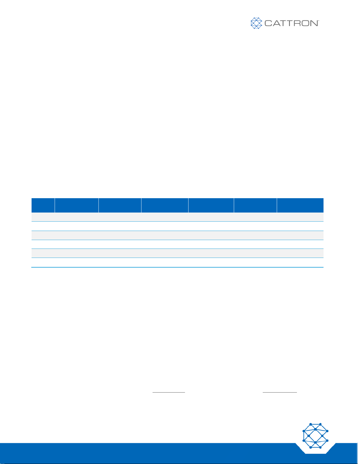
Table 1: Frequency Spacing by RF band
BAND
START FREQ HZ
END FREQ
HZ
CH SPACING KHZ
START CHANNEL
END CHANNEL
CH,
SPACING
A
418,000,000
B
433,077,500
434,777,500
25
A00
A68
2 (50kHz)
C
447,000,000
D 450,000,000
470,000,000
12.5
A00
Q00
4 (50kHz)
E
868,000,000
F
902,600,000
927,500,000
100
A00
C49
2 (200kHz)
Table 1 defines the six operating bands; currently Cattron has only released the B, D, and F bands.
▪ In North America, the D band is licensed and the F band is license exempt.
▪ Europe and many other regions including Brazil use the license exempt band B.
4.1 Rules for Frequency selection
1. A channel can be any frequency between the Start Freq. and the End Freq. that is wholly divisible by the
CH Spacing.
− Example: Band D channel 6 is 450,000,000 + (6*12,500) = 450,750,000.
And for any given frequency;
2. If any other systems (including other Safe-E-Stop systems) are operating within 10m of the location that
the Safe-E-Stop will be used, then a frequency that is at least as far away as is shown in the ‘CH
SPACING Separation’ column should be chosen.
− Example: If another system is operating on 450,700,000 required minimum separation, Table 1 is
50kHz so 450,700,000 – 50,000 = 450,650,000 and 450,700,000 + 50,000 is 450,750,000. Both of
these are within the Band Start and Band End frequencies. Make sure it is a valid channel according
to rule 1 above.
3. Finally, make sure the derived frequency is not in the table below.
Page 17
17
Version 17
Safe-E-Stop™
User Guide
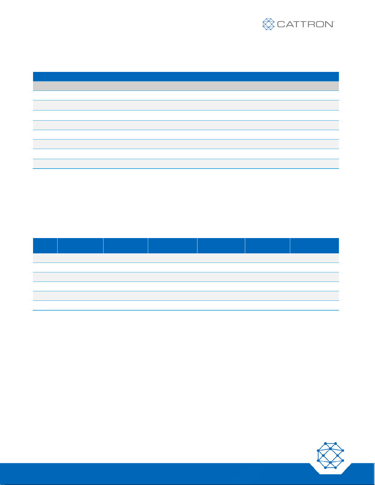
Table 2: Frequencies That Are Not Supported
AVOID FREQUENCIES
Band B
Band D
Band F
434,177,500
466,937,500
902,600,000
912,100,000
921,600,000
902,700,000
912,200,000
921,700,000
902,800,000
912,300,000
921,800,000
902,900,000
921,100,000
921,900,000
911,700,000
921,200,000
922,000,000
911,800,000
921,300,000
922,100,000
911,900,000
921,400,000
912,000,000
921,500,000
Cattron can supply support and help with frequency selection if they are provided with a list of frequencies in use
in the immediate operating location.
4.2 Site Planning
As far as is practical, RF systems frequency separation should at least be as shown in the last column of the
table below.
Table 3: Channel Spacing for Adjacent Systems
BAND
START FREQ HZ
END FREQ
HZ
CH SPACING KHZ
START CHANNEL
END CHANNEL
CH,
SPACING
A
418,000,000
B 433,077,500
434,777,500
25
A00
A68
2 (50kHz)
C
447,000,000
D 450,000,000
470,000,000
12.5
A00
Q00
4 (50kHz)
E
868,000,000
F
902,600,000
927,500,000
100
A00
C49
2 (200kHz)
NB: channels are identified on the equipment by a three-digit identity xnn; see columns 5 and 6 above.
Channels run A00 through A99, and then B00 through B99 and so on until the End Channel is reached.
For the purposes of adjacent system channel spacing we can use the figure in the final column.
This somewhat simplifies the method of determining what channels should be chosen on a site.
When all available channels have been used with the designated channel spacing (not likely with 450MHz or
915MHz band), we can start using intermediate frequencies (one channel apart) provided that they are 100m
away from the systems one channel away.
Page 18
18
Version 17
Safe-E-Stop™
User Guide
5. PSD and MSD Configuration Parameters
5.1 PSD Configuration
Your PSD has been manufactured to operate in a specific RF band, and has been built in a specific color housing.
● Within that band all users can configure the specific RF channel.
● Authorized users can set the System’s master address and the PSD’s specific sub-address.
● Various housing colors are available as options but red is standard.
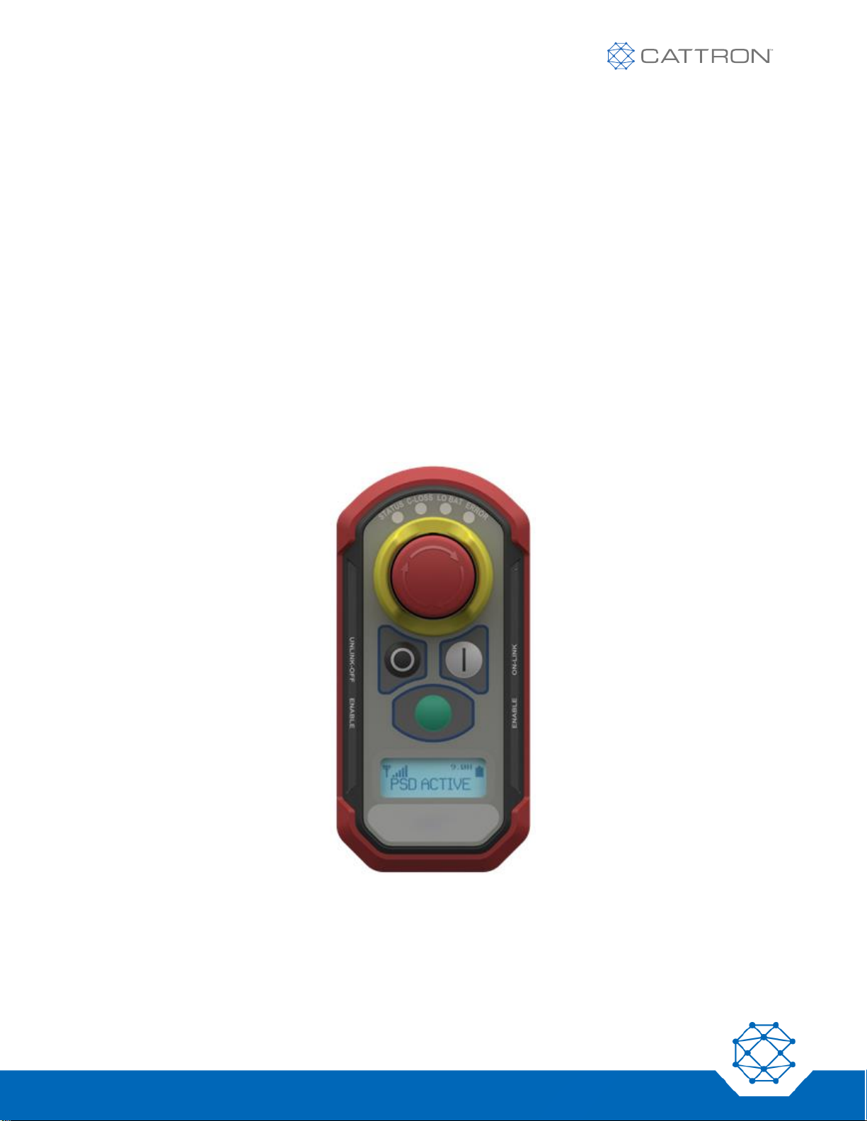
Each PSDs configuration is identified on the unit’s LCD screen.
A system of one MSD and one or more PSDs must have a correct set of configuration parameters to be able to
operate. Most of the configuration details must match exactly; only the Sub-Address must be different between
PSDs.
In summary:
▪ A PSD and MSD have one matching Master Address and each PSD has a different Sub-Address.
▪ Both PSDs and MSD have one unique frequency and master address.
Figure 1: Red PSD
The PSD will show the frequency configuration on the LCD when first turned on.
As an additional aid to visual identification and differentiation, the following is available as an option:
▪ A sheet of labels of various colors of Cattron logo as a user installation item.
Page 19
19
Version 17
Safe-E-Stop™
User Guide
5.2 MSD Configuration
Your MSD has been manufactured to operate in a specific RF band and is fitted with a specific Ethernet option.
● Within that band all users can configure the specific RF channel.
● Authorized users can set the System master address.
● Ethernet options are None, EtherNet/IP or PROFINET
Each MSD’s configuration is identified on the unit’s LCD screen.
A system of one MSD and one or more PSDs must have a correct set of configuration parameters to be able to
operate. Most of the configuration details must match exactly; only the Sub-Address must be different between
PSDs.
In summary:
▪ A PSD and MSD have one matching Master Address and each PSD has a different Sub-Address.
▪ Both PSDs and MSD have one unique frequency and master address.
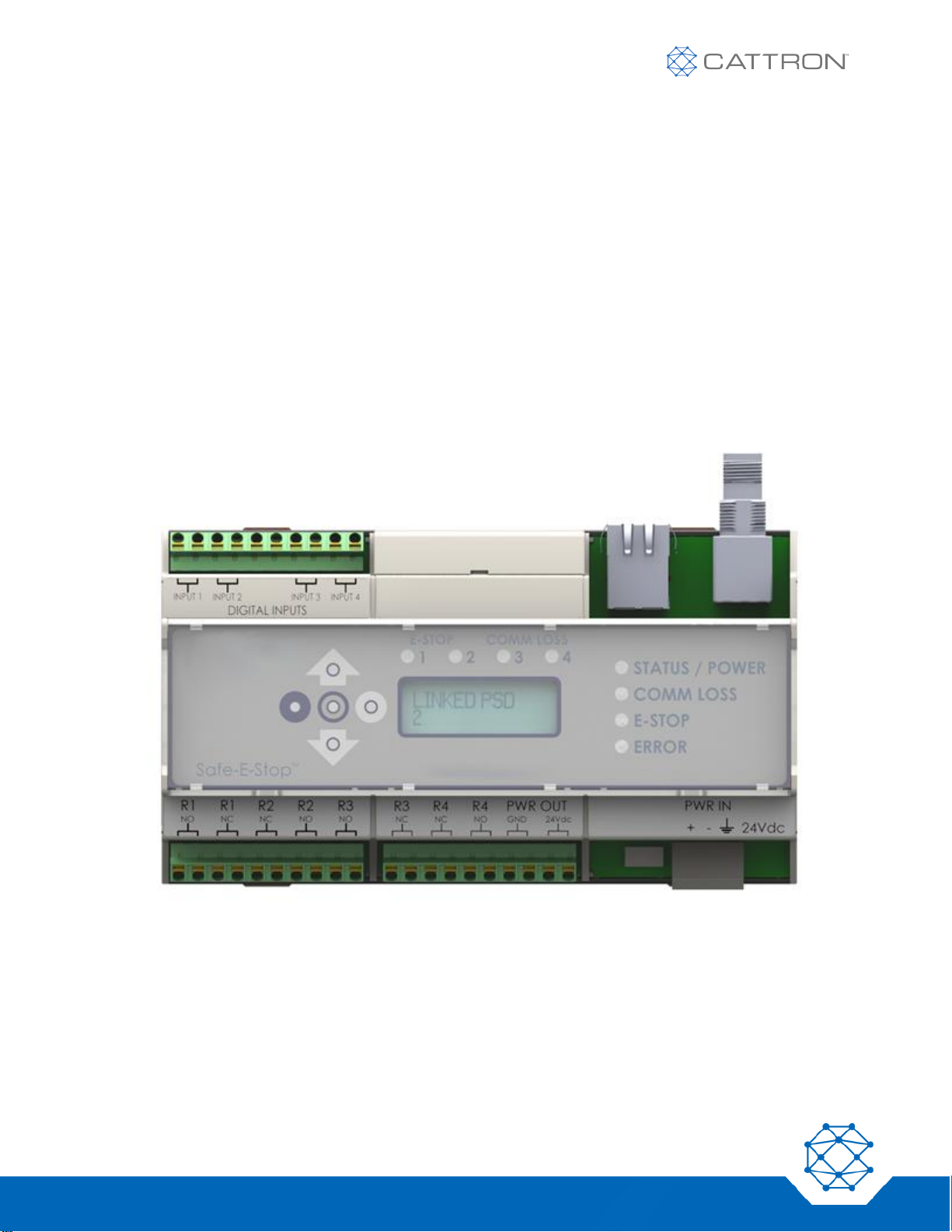
Figure 2: MSD
The MSD will show its configuration on the LCD when first turned on. The configuration can also be displayed by
scrolling down using the selection arrows.
Page 20
20
Version 17
Safe-E-Stop™
User Guide
Table 4: Frequency Bands
BAND
FREQ MHZ
TYPICALLY USED IN
A
418
China
B
433
EU & Other
C
447
EU Licensed
D
450
NA and Other Licensed
E
869
EU
F
915
NA J 429
Japan
2.19 Configuration Part Number
PSD Configuration
PSD-2-X-Y
Where 2 is the current version
Where X is the RF Band
Where Y is the color, R / G / Y / B / K (Red / Green / Yellow / Blue/ Black)
MSD Configuration
MSD-2-X-Y
Where 2 is the current version
Where X is the RF Band
Where Y is the Ethernet option, X, E, P (Excluded / EtherNet/IP / PROFINET)
Table 5: Examples of Configuration Number Use
SELLING PART #
DESCRIPTION
PSD-2-F-R
MSD-2-B-P
PSD version 2, 915MHz RF band, Red Body
MSD version 2, 433MHz RF band, PROFINET bus
Page 21
21
Version 17
Safe-E-Stop™
User Guide
6. PSD
6.1 PSD Overview
PSDs can be considered a set of wireless E-Stop switches that are dynamically linked to the MSD on an asneeded basis. The MSD does not need a PSD to be connected in order to keep its E-Stop Safety Relays closed;
as long as power is connected to the MSD and it has no faults, these relays are held closed and the hard-wired EStop circuit is maintained.
The MSD provides the physical link into the hard-wired E-Stop system of the machine. Its E-Stop Safety Relays
are wired in series with this circuit and reflecting the status of the PSDs E-Stop switches.
Up to five out of a total of fifteen PSDs can be linked to an MSD at any one time.
If a PSD is linked to the MSD, the MSD E-Stop Safety Relays are then subject to additional rules relating to the
RF communication link between the PSD and MSD, as well as the PSD E-Stop switch remaining out:
● Corruption / loss of the RF link or an E-Stop switch being pressed will open the MSD E-Stop
relays.
● Corruption / loss of the RF link will also open the COMM LOSS relays.
● A controlled process is in place to enable PSDs to link and unlink from the MSD.
6.2 PSD Status Indications
PSDs have audio, visual (LED and LCD), and haptic (vibration) warning systems to indicate the current status,
such as normal operation, low battery, low RF signal, etc.
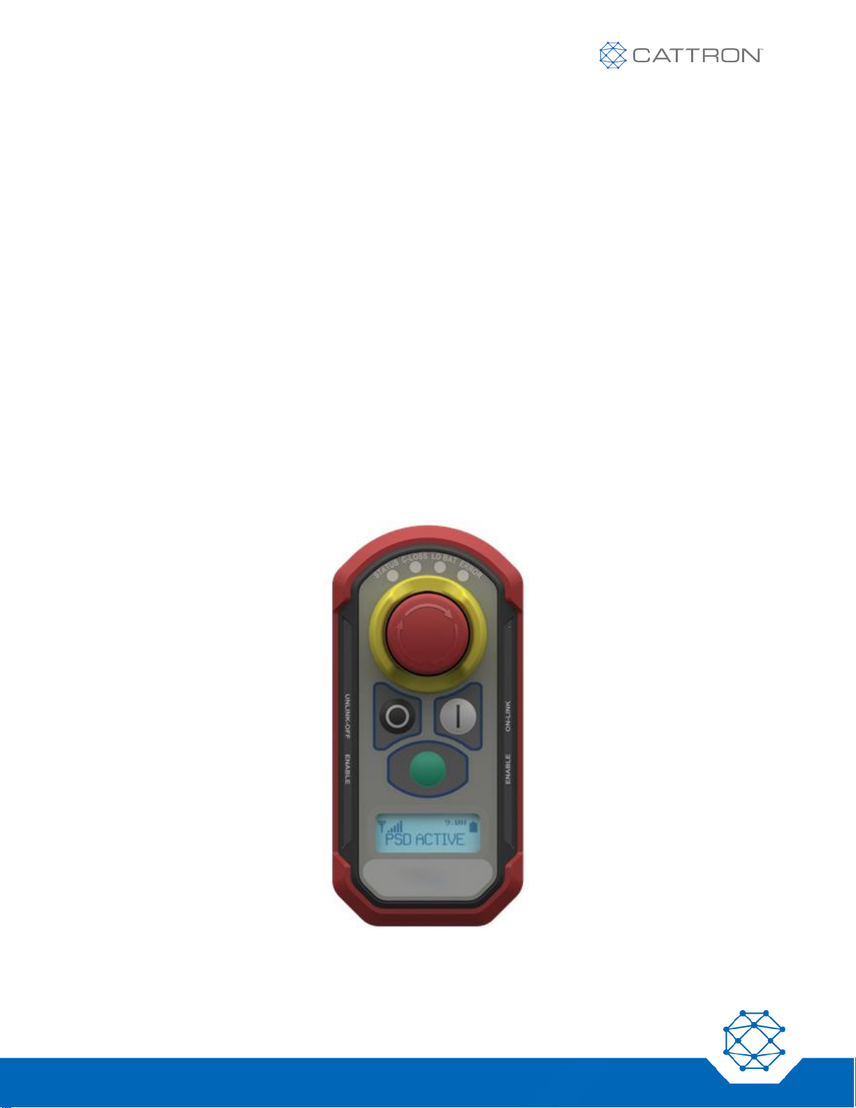
Figure 3: PSD Indications
Page 22
22
Version 17
Safe-E-Stop™
User Guide
6.2.1 PSD LEDs
Referring to Figure 3 above, there are four LEDs above the E-Stop switch. These are:
STATUS
This will be flashing:
GREEN: Normal operation
ORANGE: Conditions that require the user to be aware
RED: Conditions that require the user to take corrective action
COMM LOSS
Illuminates RED if this PSD loses communication
Illuminates ORANGE if another PSD loses communication
LOW BATTERY
Illuminates RED when the battery requires charging
ERROR
Flashes in case of internal error
6.2.1.1 PSD LCD
The LCD provides valuable information to the user. A backlight turns on each time there is a change of displayed
message and the backlight will remain on for 10 seconds.
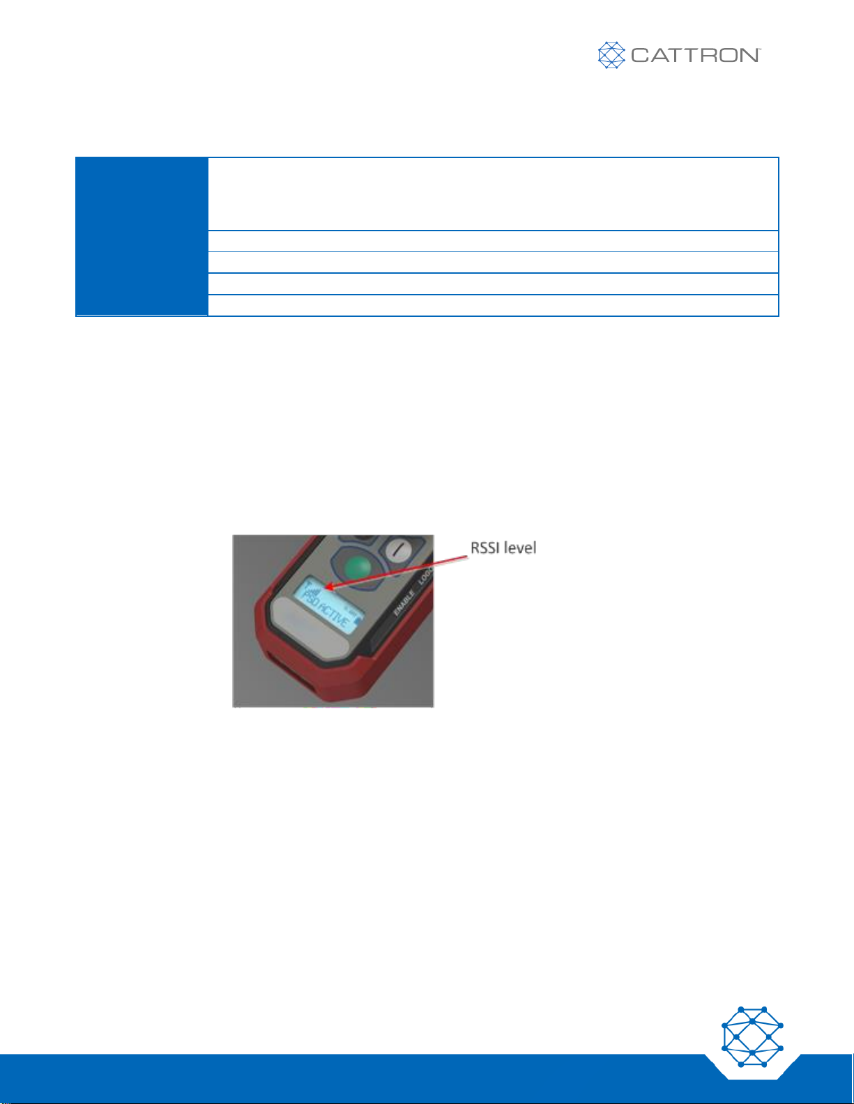
6.2.1.2 Radio signal level Monitoring
The RF signal level is displayed on the PSD using a graphic icon, as shown in Figure 4.
More bars mean more signal. Very low signal will be accompanied by the icon flashing.
Figure 4: RF Signal Level Monitoring
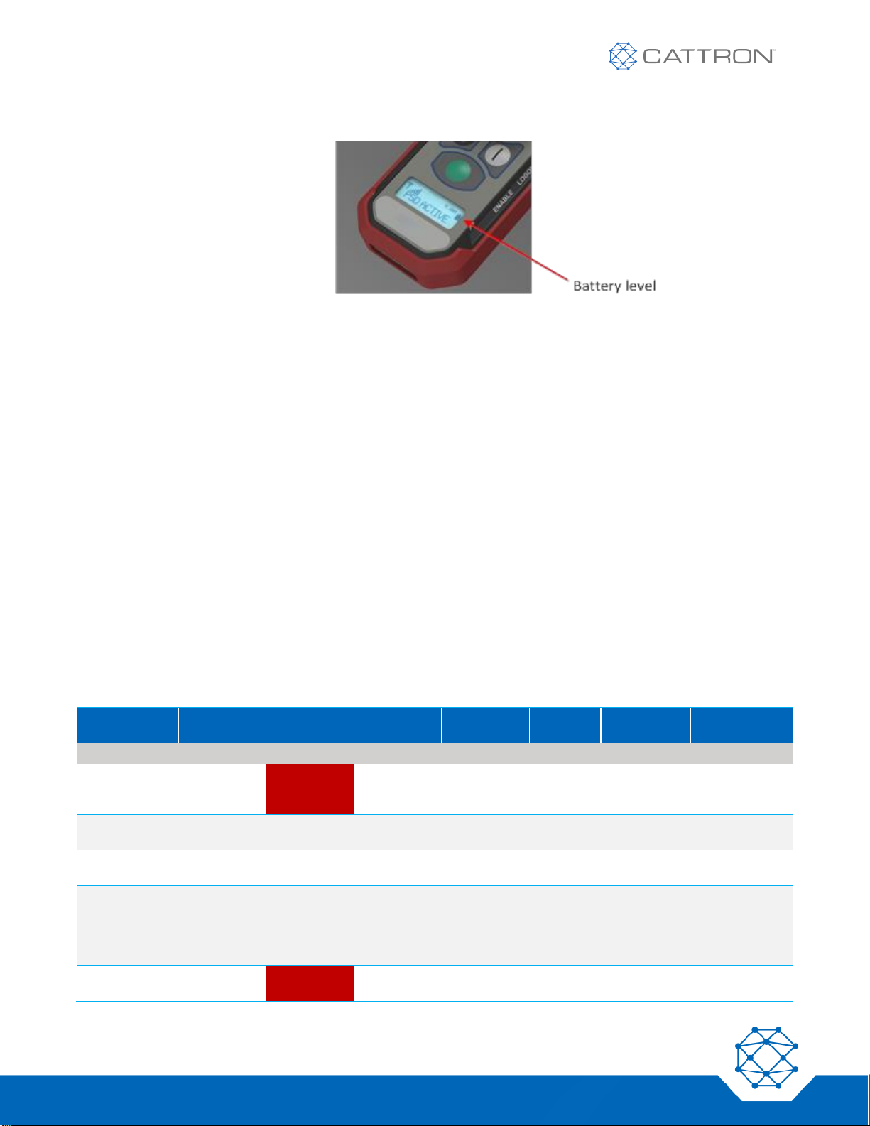
6.2.1.3 Battery Monitoring
The estimated battery level is displayed on the PSD using a graphic icon and time in hours, as shown in Figure 5.
Resolution is approximate and shown within 0.5-hour increments; accuracy may vary under some conditions,
such as low temperature.
The icon flashes when the battery charge state is very low.
Note that if the low battery LED illuminates, this indicates an imminent shut down due to low battery regardless of
the hours shown on the LCD.
Page 23
23
Version 17
Safe-E-Stop™
User Guide
Figure 5: Battery Level Monitoring
6.2.1.4 General Status Monitoring
The main LCD area gives general status as defined in the tables below.
6.3 Joining an E-Stop Group
For a PSD to link to a group:
1. Verify that the PSD has the correct configuration for the MSD to be joined.
2. Ensure the PSD is in good physical condition and that the E-Stop switch is in the released position.
3. Briefly press the ‘|’ button on the PSD and it will power on. If the ‘I’ button is pressed again it will proceed
to step 4 below. Otherwise, the LCD will display the firmware revision for 3 seconds and then for the next
3 seconds the Master-Address / Sub-Address on line 1 and the frequency on line 2, then proceed to step
4.
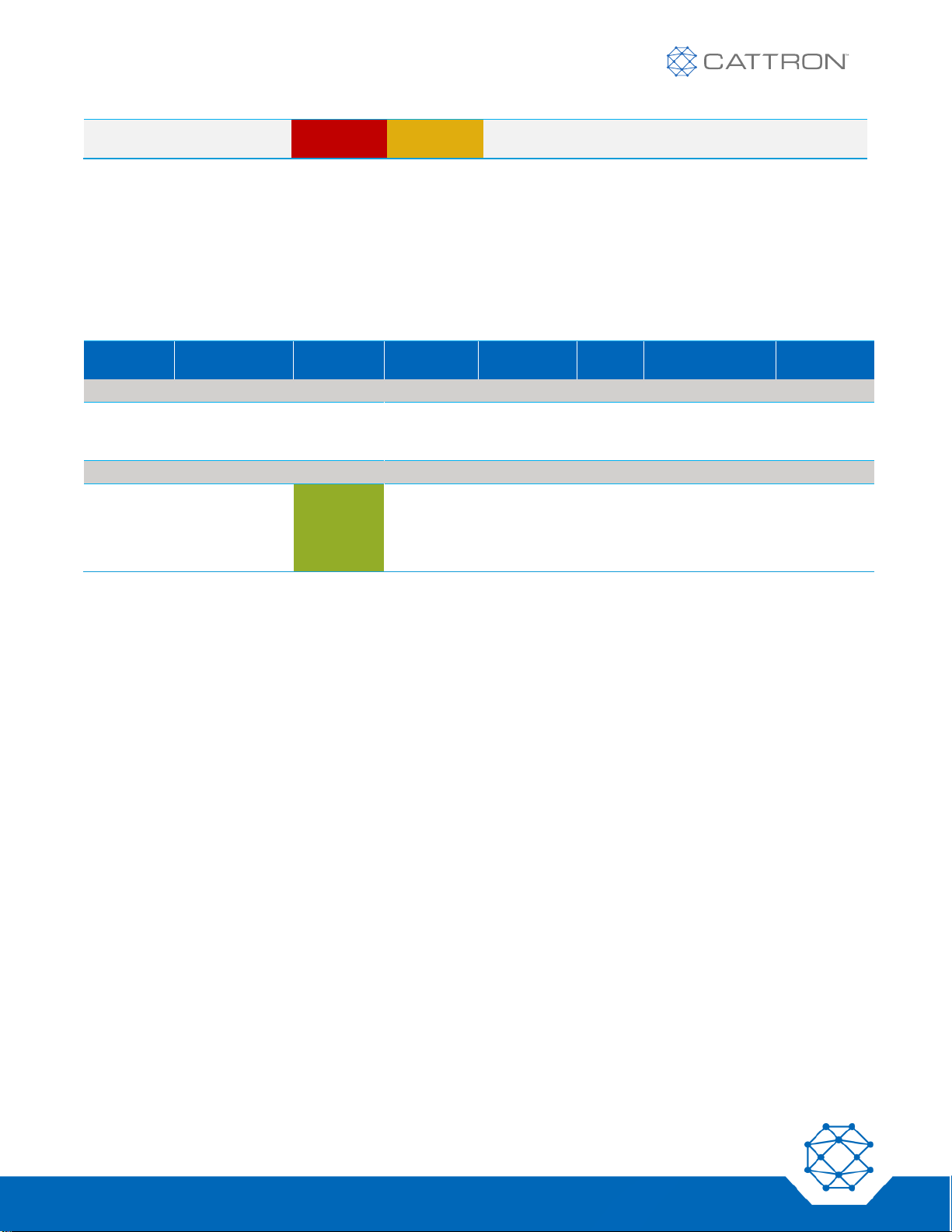
4. The LEDs and the Display will show a state from the following table. If functioning properly, the LCD
displays ‘LINK? HOLD |’. If no action is taken after 60 seconds, the unit will power off.
5. Verify that the LCD display shows sufficient battery life for the duration of work to be performed.
Table 6: PSD Unlinked Operational States
BUTTON
PRESSED
STATUS LED
COMM
LOSS LED
LOW BATT
LED
ERROR
LED
HAPTIC
FEEDBACK
DISPLAY
PSD UNLINKED STATE
PSD unlinked
- ESTOP
pressed
ESTOP
Red
3 short
pulses
REL ESTOP
PSD unlinked
1 short
pulse
LINK? HOLD I
Automatic 60
sec shutdown
3 short
pulses
SHUTDOWN
Manual
shutdown
Follow
Unlink
process,
then press
‘O’ for 3 sec
3 short
pulses
SHUTDOWN
Links full
Red
3 short
pulses
LINKS FULL
Page 24
24
Version 17
Safe-E-Stop™
User Guide
MSD not seen
Red
Flashing
Orange
3 short
pulses
MSD NOT
SEEN
When ready to join the group, ensure that you are in the work area and press and hold the ‘|’ button for longer
than half a second. Monitor the PSD display for information on linking status. The PSD returns a status message
depending on several factors as displayed in the following table.
If functioning properly, the unit will have a green flashing Status LED and the display will show ‘PSD # ACTIVE’
where # represents the PSD sub-address.
Table 7: PSD Linking Operational States
BUTTON
PRESSED
STATUS
LED
COMM
LOSS LED
LOW BATT
LED
ERRO
R LED
HAPTIC
FEEDBACK
DISPLAY
PSD LINKING STATE
PSD
linking
‘I’ for 500mS
1 short pulse as
soon as link is
established
LINKING
(flashing
until linked
PSD LINKED STATE
PSD
linked
(normal
operation
mode)
Green
(flashing)
1 short pulse (at
state transition to
PSD linked – see
PSD Linking
above)
PSD #
ACTIVE
Page 25
25
Version 17
Safe-E-Stop™
User Guide
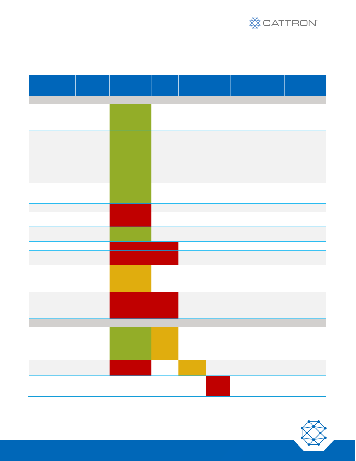
Once a PSD has joined and become an active member of the E-Stop group, the PSD displays its current status
as indicated in the following table, where # is the current ID of this or another PSD:
Table 8: Linked Operational States
BUTTON
PRESSED
STATUS LED
COMM
LOSS
LED
LOW
BATT
LED
ERRO
R LED
HAPTIC FEEDBACK
DISPLAY
PSD LINKED STATE
PSD linked
(normal
operation
mode)
Green
(flashing)
1 short pulse (at
state transition to
PSD linked)
PSD #
ACTIVE
Unlink PSD
stage 1
‘O’ until
Status LED
changes to
fast flash;
release ‘O’
for 0.5
seconds,
then
Green (slow to
fast flashing)
Returns to
normal
operation if no
2nd press
within 5
seconds
PSD #
ACTIVE
Unlink PSD
stage 2 within 5
seconds
Press ‘O’
again for 1
second
Green
(flashing fast
to off)
1 short pulse (at
state transition to
PSD unlinked)
Changes to:
PSD unlinked
state above
ESTOP pressed
ESTOP
Red (flashing)
3 short pulses
ESTOP
ESTOP pressed
– other PSD
Red (flashing)
3 short pulses
ESTOP #
ESTOP reopened
Reopen
ESTOP
Green
(flashing)
1 short pulse on all
PSDs
PSD #
ACTIVE
Comm Loss
Red (flashing)
Red
3 short pulses
COMM LOSS
Comm Loss other PSD
Red (flashing)
Red
3 short pulses
COMM LOSS
#
Comm Loss
recovery within
30 sec of
Comm Loss
‘I’ for
500mS
Orange
(flashing)
3 short pulses
LINKING
Failure to
recover from
Comm loss;
Recover at MSD
Red (flashing)
Red
flashing
after 30
sec
3 short pulses
(at state transition to
PSD unlinked)
RESET MSD
COMM LOSS
#
BATTERY/ RSSI MONITORING
Low RF signal
Green
(flashing)
Orange
flashing
3 short pulses every
10 sec, 1 short
pulse when reentering good RF
signal area
PSD #
ACTIVE
Low battery
level
Red Flashing
Orange
flashing
3 short pulses every
10 sec.
PSD #
ACTIVE
ERROR
Red
flashin
g
Page 26
26
Version 17
Safe-E-Stop™
User Guide
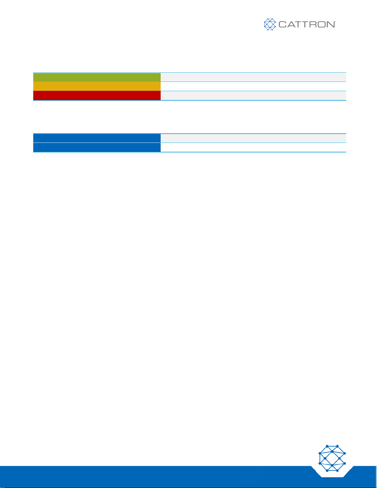
The Status LED generally has the following meaning:
Table 9: PSD Status LED General Meaning
GREEN
Normal operation
ORANGE
Items of note
RED
Action is required to correct a problem
The Haptic feedback (vibration) generally has the following meaning:
Table 10: Haptic Feedback General Meaning
ONE PULSE
Confirmation
THREE PULSES
Warning of an abnormal event
6.4 Normal Operation
Once linked to an MSD, normal operation can commence.
For normal operation all linked PSDs must have their E-Stop switches released, good battery capacity, and be
within a good RF range (typically within 300 feet of the machine, but the distance will vary by environment).
6.4.1 Communication Loss
Moving a PSD out of RF range results in an E-Stop; this is a safety-critical feature to ensure that the E-Stop of a
linked PSD is always available. As this is not ideal, the PSD warns the user if the signal is getting too low by
flashing the RSSI ICON, flashing the status LED red, (requiring action by the user), changing the COMM LOSS
LED to orange, and vibrating in groups of 3 pulses. The user must move closer to the machine or risk causing an
E-Stop by COMM LOSS.
If a PSD moves out of range and causes a COMM LOSS, both the E-Stop and COMM LOSS safety relays on the
MSD open.
6.4.2 Communication Loss Recovery Stage 1
The PSD causing the COMM LOSS has 30 seconds to move back into RF range, after which the user can press
the ‘|’ button on the PSD to recover the MSD operation. The machine will still need to be reset.
6.4.3 Communication Loss Recovery Stage 2
If the PSD is not moved back into range within 30 seconds, a full COMM LOSS is enforced. All PSDs unlink and
an MSD reset will be required by pressing a button that is wired to the MSD COMM LOSS reset switch safety
inputs. Afterwards, all PSDs will need to relink to rejoin the operation, and the machine will need to be reset.
This process makes it possible to recover from a PSD that has, for instance, been accidentally removed from site
without de-linking.
As part of the recovery process, it is important that all users are accounted for.
6.4.4 Issuing an E-Stop
In normal operation, the E-Stop switch can be pressed at any time. This results in the MSD E-Stop Safety Relays
opening within 500mS, bringing the machine to a safe state. Note that the MSD COMM LOSS relays remain
closed.
The PSD issuing the E-Stop will have the Status LED flashing red and the display will show ESTOP. The PSD will
vibrate three times.
Page 27

27
Version 17
Safe-E-Stop™
User Guide
The Status LEDs of other PSDs (if any) will flash orange. The display will show ESTOP #, where # is the number
of the issuing PSD. The PSD will vibrate three times.
6.4.5 Recovery of an E-Stop
To recover following an E-Stop, the problem requiring the E-Stop must be satisfactorily resolved. The PSDs that
issued the E-Stop need to release their E-Stop switches, after which the MSD E-Stop Safety Relays will close and
the machine can be reset to restart operations.
6.5 Leaving an E-Stop Group
An active member of the E-Stop group may have reason to leave an operation, such as completing work, needing
a rest break, changing shift, etc.
Members may leave the group at any time without causing an E-STOP or COMM LOSS by following a simple
procedure that informs the MSD that the PSD user wants to leave the group in a controlled and safe way.
The user simply needs to press and hold the ‘O’ button for more than 1 second until the Status LED begins
flashing, then release the ‘O’ button for slightly more than 0.5 seconds, then press the ‘O’ button again for at least
1 second. The PSD will then unlink from the MSD. Note that if the ‘O’ button is not pressed a second time within 5
seconds, the PSD will return to normal operational state. This process ensures a PSD is not accidentally unlinked.
When the PSD transitions to the unlinked state the PSD vibrates once to confirm and the LCD displays “LINK?
Hold I.”
6.6 Switching OFF the PSD
From the unlinked state, the PSD will power down after 60 seconds without input. The PSD can also be powered
down manually by holding the ‘O’ button for three seconds.
Note that if the PSD is in Error state it will power off after 3 minutes.
6.7 Charging the Battery
1. Ensure the charging adapter is connected to a power socket.
2. Connect the adapter to the charging cradle.
3. Insert the PSD into the cradle.
4. Ensure the power to the charging adapter is switched on and the LED on the adapter is illuminated.
5. Battery charging now begins.
6. The PSD battery charging process will be completed within approximately3 hours.
6.7.1 Battery Capacity and Operating Life
The battery in the PSD will slowly degrade over time and will reach 80% capacity after approximately 500 charge/
discharge cycles, reducing the maximum run time of the PSD. Other factors affect the run time of the PSD,
including temperature; very low temperatures will significantly reduce available battery capacity. At -20°C the
capacity will be approximately 30% lower than at 25°C.
Cattron recommends that the customer estimate the usage of their PSDs in order to plan for a battery
replacement after 500 charge/ discharge cycles.
The battery is not user serviceable. The PSD must be returned to Cattron or an authorized agent for service.
Page 28
28
Version 17
Safe-E-Stop™
User Guide
6.8 PSD Belt Clip
The PSD belt clip provides a secure means to wear the PSD so that the E-Stop switch is presented with the best
possible aspect for immediate access; in a safety-critical application this is superior to an end-mounted switch that
may require a two-handed approach to activate.
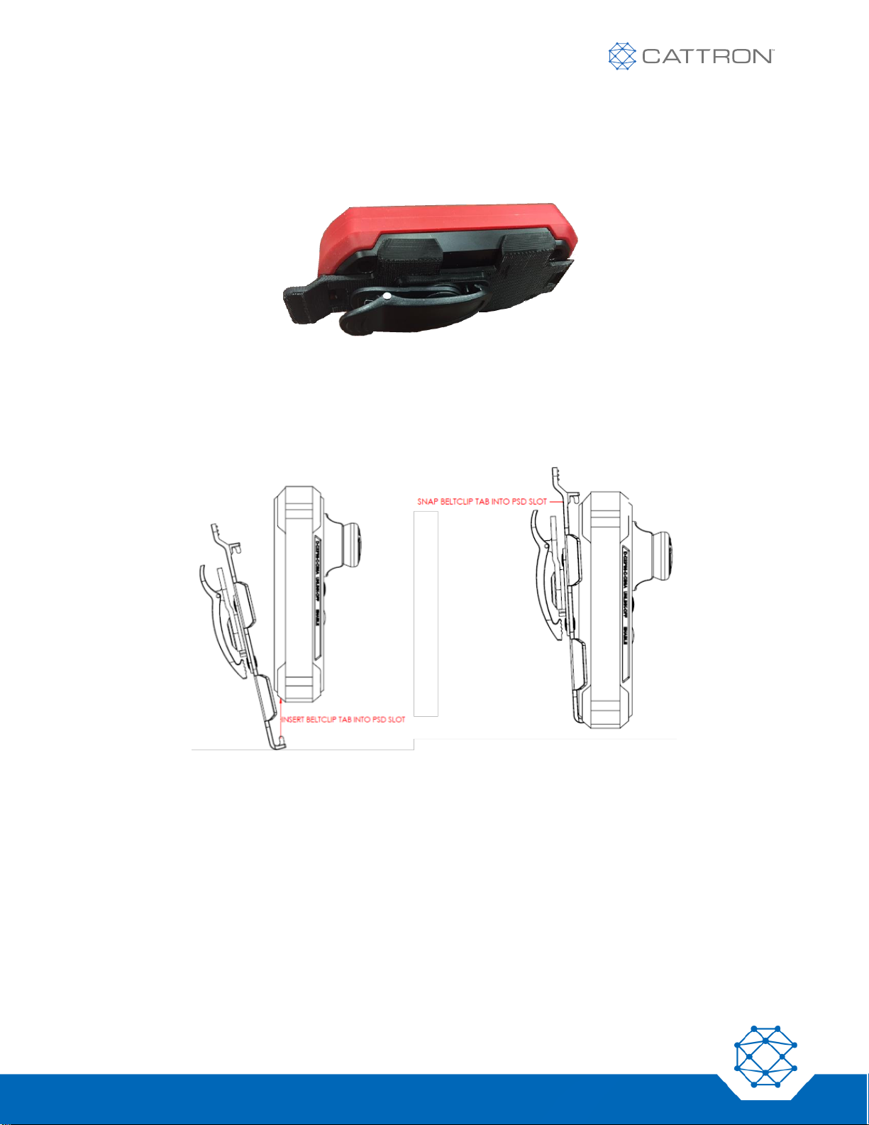
Figure 6: PSD Belt Clip
The belt clip should be attached to a belt that is no wider than 1.5 inches (38mm).
The PSD attachment can be rotated as required by the user.
To attach the PSD to the clip, see the diagram below. The PSD can be attached to the clip either way round.
Figure 7: PSD Belt Clip Attachment
Page 29
29
Version 17
Safe-E-Stop™
User Guide
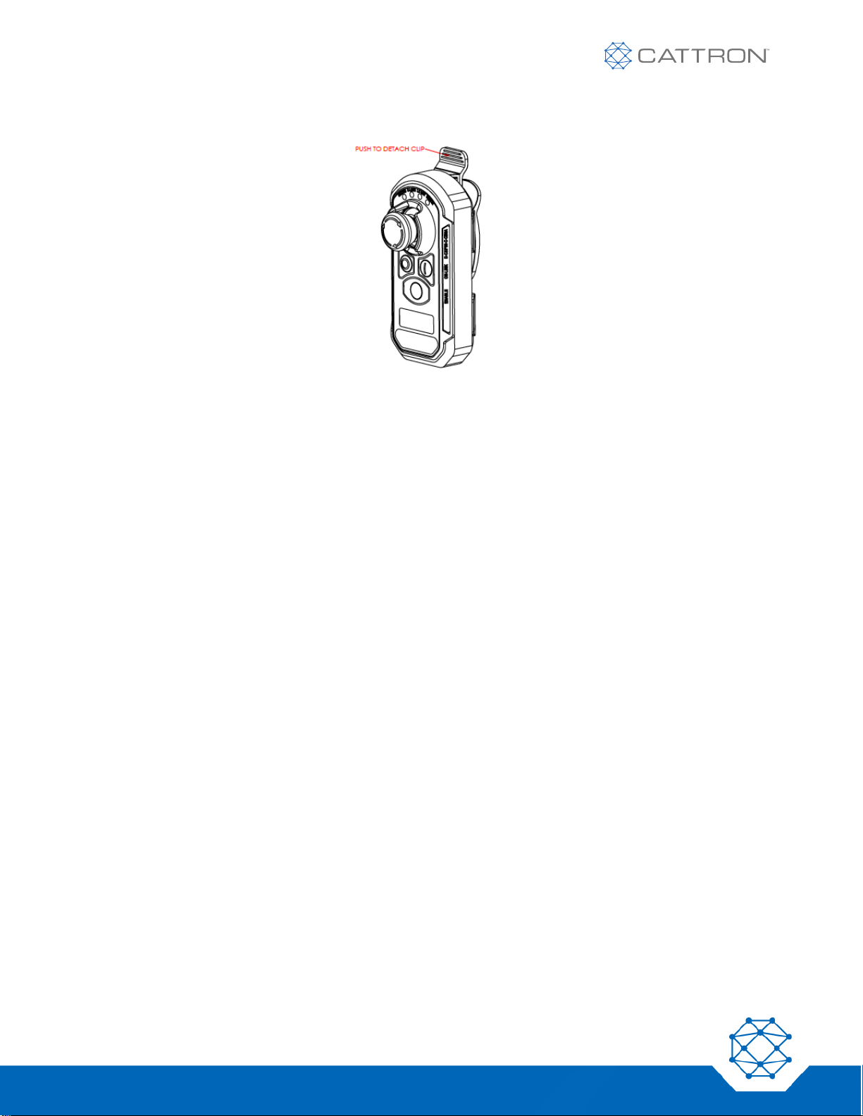
To detach the PSD from the clip, press the tab away from the PSD, as shown in Figure 8.
Figure 8: PSD Belt Clip Detachment
Page 30

30
Version 17
Safe-E-Stop™
User Guide
7. Battery Chargers
7.1 General Information
There are two versions of the battery charger: a single-bay unit with part number 1PRT-8778-A001, and a six-bay
charger with part number 1PRT-8779-A001.
Both units have been specifically designed to work with the Cattron Safe-E-Stop PSDs, versions 1 or 2.
These chargers will rapidly charge the battery, monitor the battery for safe charging, and provide years of reliable
service with proper care.
The chargers require no special maintenance, but in the event of damage to the unit, the external power supply,
or cord, contact Cattron customer service for a replacement.
Unlinked PSDs should not be visible to personnel in the area to potentially be confused for an available E-Stop
switch. If PSDs in chargers are unlinked, they should be placed within a secondary enclosure or positioned so
that the E-Stop switch faces toward a wall and away from personnel.
Always fully charge the PSD before initial use. The PSD’s battery may be charged when it is partially discharged.
It is neither necessary nor advantageous to fully discharge the battery before recharging.
Return the PSD to Cattron for service or recycling. Do not discard unwanted PSDs in the trash or incinerate. The
battery may explode if exposed to fire or excessive heat.
7.2 Caution
Keep the battery charger in a dry location and only operate it within a temperature range of 0 to 40° Celsius (32 to
104° Fahrenheit).
Make sure contacts in the charging bay and the PSD are clean. If the contacts require cleaning, disconnect the
charger from the power supply and wipe with a dry, lint-free cloth.
Do not allow wire or metal objects to touch contacts in the charging slot or any internal part of the charger.
Do not remove the charger’s housing or make any modification to the charger. The charger has no user-
serviceable parts.
Use only the power supply included with the charger. Use of other power supplies may damage the charger or the
battery being charged.
Page 31
31
Version 17
Safe-E-Stop™
User Guide
7.3 Single Bay Charger
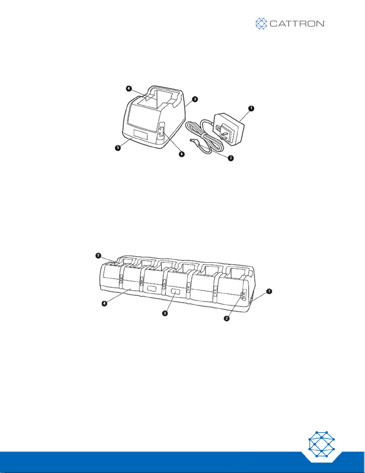
A single-bay charger can charge one PSD at a time. A PSD will fully charge within approximately 3 hours.
Figure 9: Single Slot Charger Features and Power Cord
1. Power supply (input 100V – 240V AC).
2. DC plug (9V DC output).
3. DC power connection – back of charger.
4. Charging slot for PSD-1-x.
5. Charger base.
6. Charge status and power-on LEDs.
7.4 Six-Bay Charger
A six-bay charger can charge up to 6 PSDs at a time. Each PSD will fully charge within approximately 3 hours.
Figure 10: Six Slot Charger Features
1. DC power connection.
2. Charge status and power-on LEDs.
3. Quick reference information for charge status LEDs.
4. Charger base.
5. Charging slots for batteries.
Page 32
32
Version 17
Safe-E-Stop™
User Guide
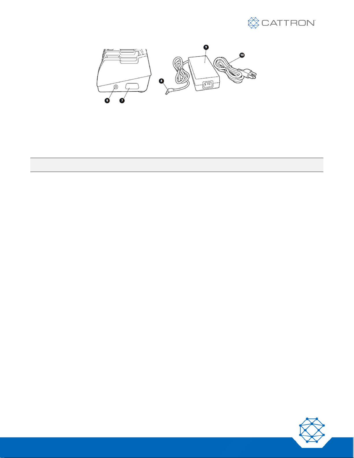
Figure 11: Six Bay Charger, Side View and Power Cord
6. DC power connection for power supply (included).
7. DC power connection for optional 12V-24V kit.
8. DC plug (12V DC output).
9. Power supply (input 100V – 240V AC).
10. AC cord for power supply.
NOTE: Additional reference information for charge status LEDs is located on the bottom of the charger.
Page 33
33
Version 17
Safe-E-Stop™
User Guide
7.5 Battery Charger Status and Indicators
The Battery charger LEDs indicate the current charging state.
The bottom LED illuminates Green when the unit is connected to power.
The top LED is the status LED and conforms to the Table 11.
When the charge status LED flashes RED, a fault condition exists and when it flashes ORANGE you are receiving
an advisement concerning the condition of the PSD’s battery. There are two flash patterns for faults and two flash
patterns for advisements. Each is described in Table 11.
To initiate charging, place the PSD in a charging slot. The Top LED will initially illuminate RED to confirm the
battery is charging normally.
When charging is complete and after removing the PSD, the charge status LED will illuminate ORANGE for a few
seconds. Allow the charge status LED to go off before placing another PSD in the charging pod.
Table 11: Battery Charger Status indication
TOP LED COLOR
FLASH PATTERN
MEANING
GREEN
FLASHING
Battery’s capacity is over 80% charged. It is recommended that the battery be
charged to at least 80% capacity before use.
GREEN
SOLID
Battery is fully charged and charging has terminated. When the PSD’s battery
is fully discharged, it will be completely charged in less than 3 hours.
RED
SOLID
Battery in PSD is rapid charging. Charge level is less than 80% of battery
capacity.
RED
TWO FLASHES
Indicates battery contact in the PSD is “open” and current is not passing
through the (+) and (-) contacts on the battery. A double flash pattern is also
provided if the battery has a short circuit. For either condition, charging is
immediately terminated. Have the battery checked by a qualified technician.
RED
THREE FLASHES
High temperature condition. Battery temperature is >45°C and cannot be
charged safely. Do not attempt charging a battery if it is excessively warm
when touched.
AMBER
SOLID
Low temperature condition. Battery temperature is <0°C (below freezing) and
cannot be charged. Charger will monitor battery temperature for two hours and
begin charging once it rises above 0°C. Remove battery from charger if not
charging after two hours.
AMBER
ONE FLASH
Under-charged condition. Battery remains under charged after the charger
completes a full charging cycle. A single flash pattern is also provided if the
battery temperature remains <0°C (below freezing) after monitoring for two
hours.
Page 34

34
Version 17
Safe-E-Stop™
User Guide
8. MSD
8.1 MSD Overview
The MSD provides the physical link into the machine’s hard-wired E-Stop system. Its E-Stop Safety Relays are
wired in series with this circuit.
The PSDs are dynamically linked to the MSD on an as-needed basis.
A controlled process must be in place to ensure that PSD users verify that they have linked to the MSD when
joining and when leaving have unlinked from the MSD.
Remember that the PSD has distinct and clear operator feedback to show if it is UNLINKED or LINKED. Provided
the user is correctly trained and aware, there should be low likelihood that an operator has failed to link yet
believes that they are linked. Additional confirmation may be obtained by having a PLC monitor the Ethernet port
data and turn on a lamp or buzzer by the machine when any PSD green button is pressed. This can be used as a
final confirmation that the PSD is on and linked to that machine.
NOTE 1: The MSD does not need a PSD to be connected in order to keep its E-Stop Safety Relays closed; as
long as power is connected to the MSD and it has no faults, these relays are held closed and the hardwired E-Stop circuit is maintained; only the COMM LOSS relays will be open without a PSD connected.
NOTE 2: The COMM LOSS relays are an automatic function and have a safety rating of SIL3. The COMM LOSS
relays are a positive indication that at least one PSD is linked and that none of those PSDs are in a
state of COMM LOSS.
NOTE 3: The E-Stop relays are triggered by human action (the PSD E-Stop switch) and so are not an automatic
function; however, from the point of being triggered (E-Stop switch pressed by the user) the system has
a SIL3 performance level.
NOTE 4: "If the machine will at times be used without any of the Safe-E-Stop PSDs in use the MSD COMM
LOSS relays will be open; therefore the COMM LOSS relays cannot be wired in series with the E-Stop
relays because the hard-wired machine E-Stop circuit will never be closed; therefore, if the COMM
LOSS relays are required they would either a) need an override switch, b) not be used or c) used to
alter operating mode by a PLC."
NOTE 5: When one or more PSDs are linked the E-Stop and COMM LOSS relays require good communications
to stay in their closed state; a COMM LOSS will be triggered by any PSD leaving the operating range or
RF interference corrupting or blocking the RF signal.
Page 35

35
Version 17
Safe-E-Stop™
User Guide
8.2 MSD Connections
The MSD features multiple interface ports for various connections:
▪ COMM LOSS reset switch connects to inputs 1 and 3 (polarity reversible)
▪ INPUTS 2 & 4 are unused (polarity reversible)
▪ RJ45 Ethernet port
▪ Antenna port TNC
▪ 24Vdc power input (9-36Vdc)
▪ E-Stop Safety Relay outputs R1 & R2
▪ COMM Loss Safety Relay outputs R3 & R4
▪ Auxiliary dc output (same as 24Vdc input voltage but protected by a fuse)
CAUTION
The choice of connection will be determined by the safety level required for the target application and machine.
To achieve SIL3 capable safety levels a dual channel connection approach will be required and is
recommended, but single channels are optional for lower safety levels and are also shown below.
Additionally, it must be remembered that the Ethernet port is not safety-critical, only informational, therefore the
functionality of the green button on the PSD should not be used for safety-critical functionality such as
restarting the machine.
USE OF THE GREEN BUTTON FOR SAFETY-CRITICAL FUNCTIONS COULD RESULT IN UNEXPECTED
ACTUATION OF FUNCTION AND MAY LEAD TO INJURY OR DEATH.
Page 36
36
Version 17
Safe-E-Stop™
User Guide
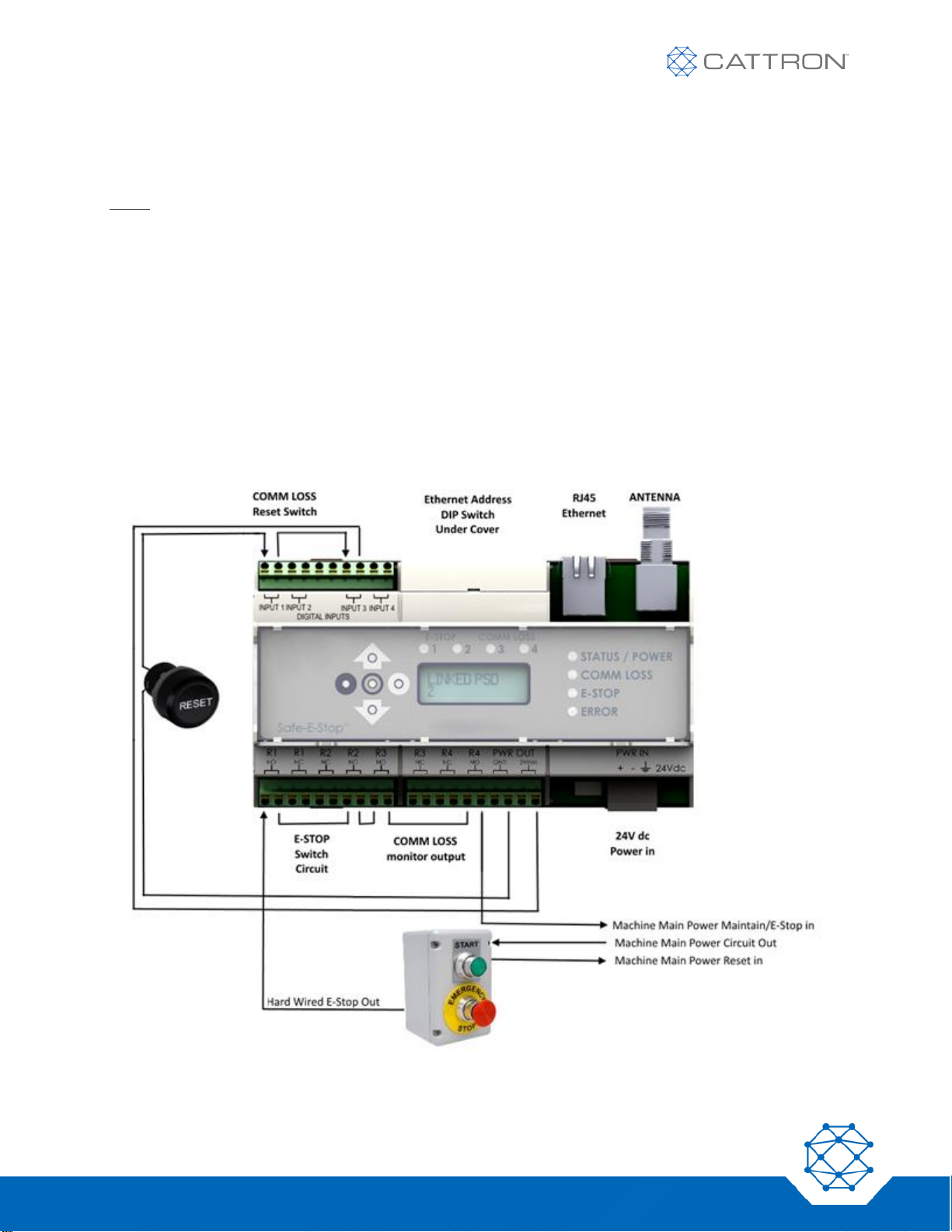
8.2.1 Single Channel Connections Example when using the COMM LOSS Relays
The following configuration combines the SIL3 function of the COMM LOSS relays with the systematic capability
of 3 provided by the E-Stop relays in a single channel configuration.
If a single PSD is always to be used, then use of the COMM LOSS relays will also provide additional status
information. Once one PSD is ‘LINKED’, it is placed into service as an additional E-Stop and the COMM LOSS
relays are closed. If a user fails to link their PSD and confirm that it is linked, it will not be detected and the
machine could be reset unless the COMM LOSS relays are wired in series with the E-Stop relays, this will enforce
the need for a single PSD.
However, each additional PSD will not make any further difference to the COMM LOSS relays; if additional
users fail to LINK correctly and confirm LINK status, it will not be detectable via the COMM LOSS relays. If further
confirmation is required, it is possible to implement additional verification using the Ethernet bus data and a PLC
control system to ensure that one, two, or a minimum number of PSDs is linked for operation to commence. Once
linked, any PSD that has a COMM LOSS will cause the COMM LOSS and E-Stop relays to open.
Additionally, if the machine is to be run without a PSD connected at times, this will not be possible without either
overriding or not using the COMM LOSS relays, because their state will be open without a linked PSD.
The single channel connection method below will not provide protection against an external wiring fault.
Figure 12: MSD Typical Single Channel Connections When Using the COMM LOSS Relays
Page 37
37
Version 17
Safe-E-Stop™
User Guide
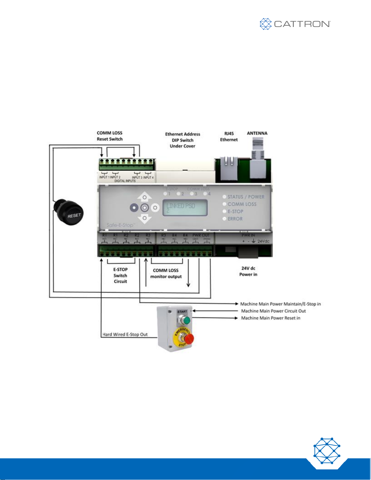
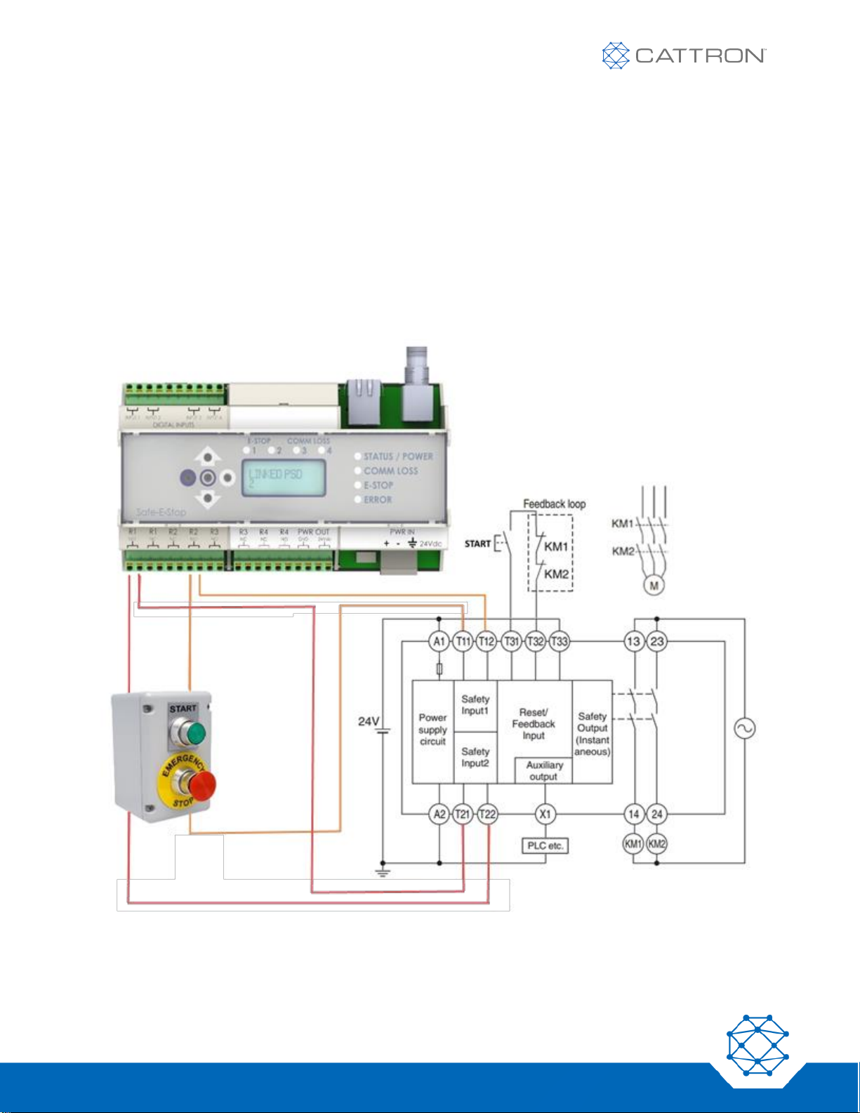
8.2.2 Single-Channel Connections Example when not using the COMM LOSS Relays
The following configuration does not use the SIL3 function of the COMM LOSS relays but does use the
systematic capability of 3 provided by the E-Stop relays.
Where a strong process is in place that ensures the users confirm that the PSD is LINKED before starting to work,
the use of the COMM LOSS relays may not be needed. The Ethernet bus may be used to give visual feedback of
PSD status or total number of PSDs linked, or to allow the green button to light a lamp, etc. This makes it possible
to run the machine with the hard-wired E-Stop switch in use and no PSD in use.
The single channel connection method below will not provide protection against an external wiring fault.
Figure 13: MSD Typical Single-Channel Connections When Not Using the COMM LOSS Relays
Page 38
38
Version 17
Safe-E-Stop™
User Guide
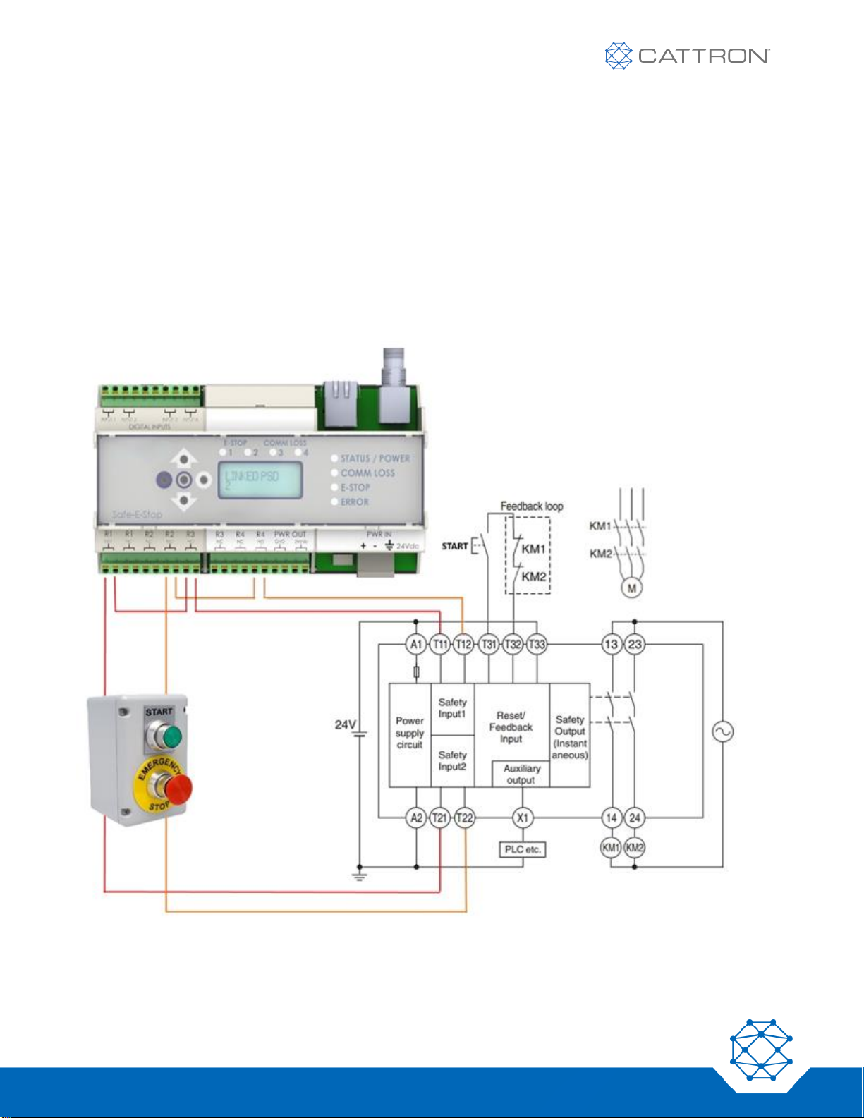
8.2.3 Dual-Channel Connections Example when not using the COMM LOSS Relays
The following configuration provides the systematic capability of 3 provided by the E-Stop relays in a dual channel
configuration.
Where a strong process is in place that ensures the users confirm that the PSD is LINKED before starting to work,
the use of the COMM LOSS relays may not be needed.
The Ethernet bus may be used to give visual feedback of PSD status or total number of PSDs linked, or to allow
the green button to light a lamp, etc. This makes it possible to run the machine with the hard-wired E-Stop switch
in use and no PSD in use.
The dual-channel connection method below ensures a high level of reliability and monitoring is imposed; no
single-channel wiring fault will be possible.
The COMM LOSS reset function is not shown but is still required, see Fig 12.
Figure 14: MSD Typical Dual Channel Connections When Not Using the COMM LOSS Relays
Page 39
39
Version 17
Safe-E-Stop™
User Guide
8.2.4 Dual-Channel Connection Example using E-Stop relays and the COMM LOSS relays
The following configuration combines the SIL3 function of the COMM LOSS relays with the systematic capability
of 3 provided by the E-Stop relays in a dual channel configuration.
The Ethernet bus may be used to give visual feedback of PSD status or total number of PSDs linked, or to allow
the green button to light a lamp, etc. This makes it possible to run the machine with the hard-wired E-Stop switch
in use and no PSD in use.
The dual-channel connection method below ensures a high level of reliability and monitoring is imposed; provided
the safety PLC inputs are OR’d, no single-channel wiring fault will be possible.
Additionally, if the machine is to be run without a PSD connected at times, this will not be possible without either
overriding or not using the COMM LOSS relays, because their state will be open without a PSD linked.
The COMM LOSS reset function is not shown but is still required, see Fig 12.
Figure 15: MSD Typical Dual Channel Connections When Using the COMM LOSS Relays
The COMM LOSS reset function is not shown but is still required, see Fig 12.
Page 40
40
Version 17
Safe-E-Stop™
User Guide
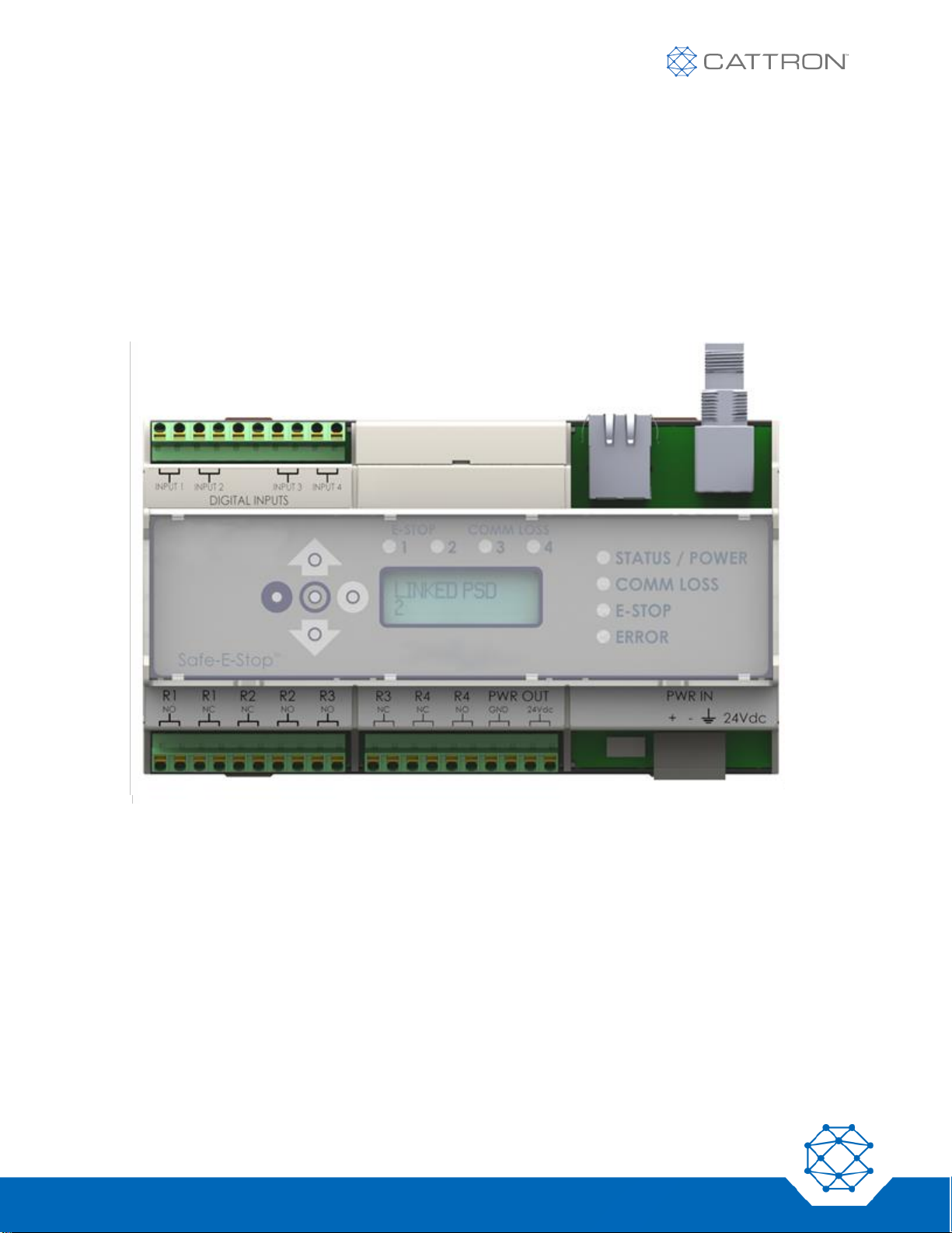
8.3 MSD Status Indicators
The MSD provides an overview of operational status with both LED and LCD.
The Ethernet port can provide detailed operational status of linked wireless E-Stop’s to operations personnel. This
information includes:
▪ The number and identity of linked PSDs
▪ The activation state of each PSD’s green enable button
▪ The state of each PSD’s E-Stop switch
▪ The communication state and RF signal level of each PSD
Figure 16: MSD Status Indicators
Page 41
41
Version 17
Safe-E-Stop™
User Guide
MSD LEDs
The Status of the four Safety relays is indicated by the four red LEDs above the LCD. When the LED is on the NO
terminal will be closed, and when the LED is off (and in all cases when the MSD has no power) the NC terminals
will be closed.
The four LEDs to the right of the LCD relate more to operational status as follows:
▪ STATUS / POWER shows that the unit is on and other various states, as shown in Table 12.
▪ COMM LOSS illuminates if one of more PSDs are either in danger of losing, or have lost, communication.
▪ E-Stop illuminates when one or more PSDs have an active E-Stop switch.
▪ The ERROR LED illuminates if there is an internal error.
MSD LCD
The MSD LCD displays the current operational state, as detailed in Table 12.
The LCD also provides additional information when using the five-button cluster to the left.
The MSD LCD remains illuminated.
When first turned on, the MSD display will show the current firmware revision for three seconds, followed by the
master address on line 1 and the frequency on line 2 for the next three seconds. The LCD will then revert to the
indications on the table below.
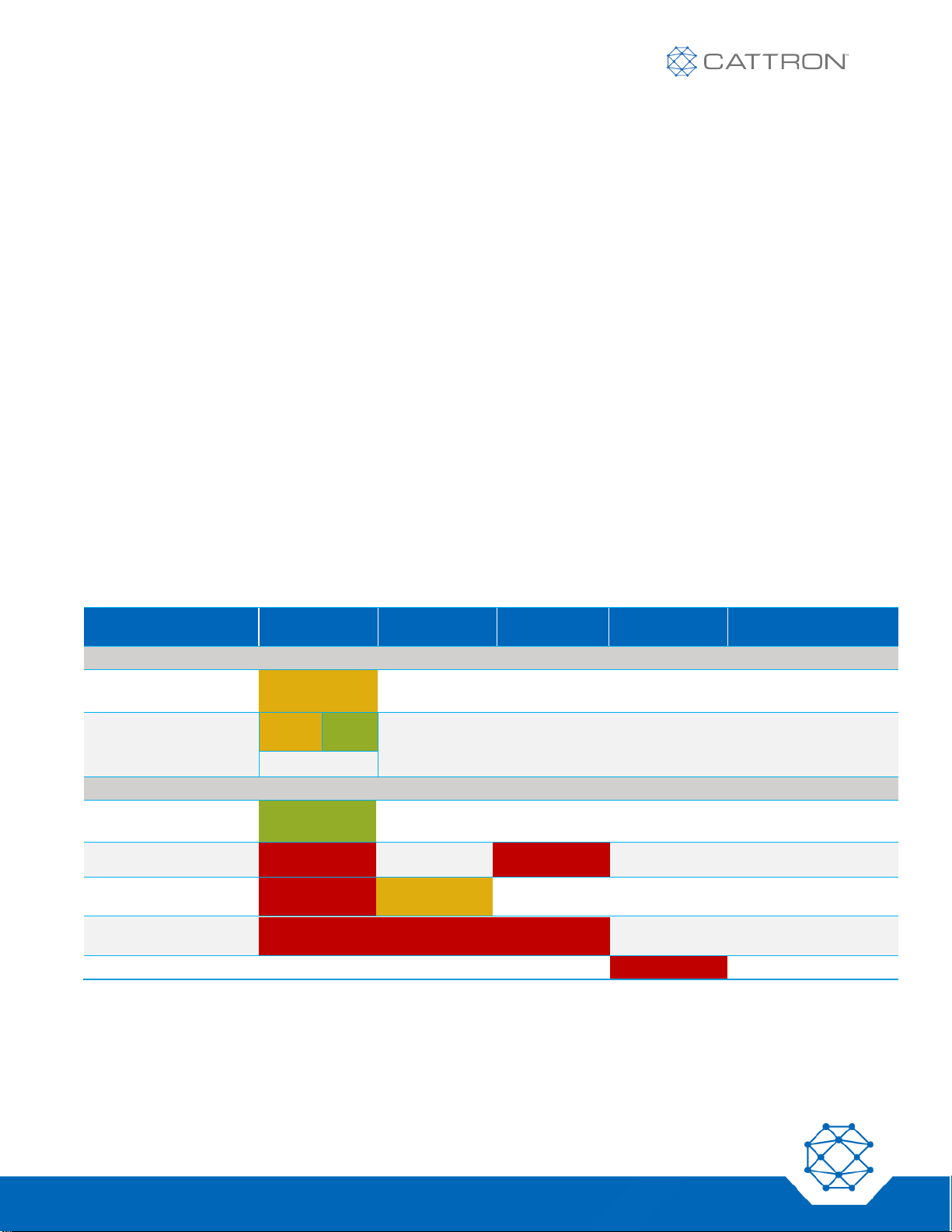
8.4 MSD Operational States
Table 12: MSD Operational States — # represents the PSD sub-address
SIDE STATUS
LED
SIDE COMM
LOSS LED
SIDE ESTOP
LED
SIDE ERROR
LED
DISPLAY
MSD INACTIVE STATE
No PSDs linked
Orange
LINKED PSD
NONE
Any PSD Linking
Orange
Gree
n
LINKING #
Flashing
MSD ACTIVE STATE
PSDs linked
(normal mode)
Green
LINKED PSD # # # # #
ESTOP pressed
Red
Red ESTOP # # # # #
Low RF signal
Red
Orange flashing
PSD (with low signal) #
blinking
COMM LOSS longer
than 30 seconds
Red
Red
Red
COMM LOSS PRESS
RESET
ERROR
Red
Page 42

42
Version 17
Safe-E-Stop™
User Guide
8.5 MSD Information and Setup
The MSD LCD, in combination with the five buttons to the left, allow access to three different screens, plus the
bootup screen, that shows the current firmware revision. The screens may be cycled by using the up and down
buttons on the MSD. The screens are:
▪ The default status screen, See the Table 12.
▪ Ethernet parameters page, which will show one of the following:
o Ethernet Module not installed
o EtherNet/IP
o PROFINET
o IP address type (static or DHCP)
o IP address value
o Subnet mask.
▪ The RF Received Signal Strength Indication (RSSI) screen; this shows the signal strength of each PSD that
is currently linked. A lower number (around 50-60) indicates a very strong signal while a higher number
(around 90-100) indicates a weaker signal.
▪ Operation parameters page: shows System Address and RF Frequency (MHz)
Page 43
43
Version 17
Safe-E-Stop™
User Guide
8.6 MSD Ethernet Address Configuration
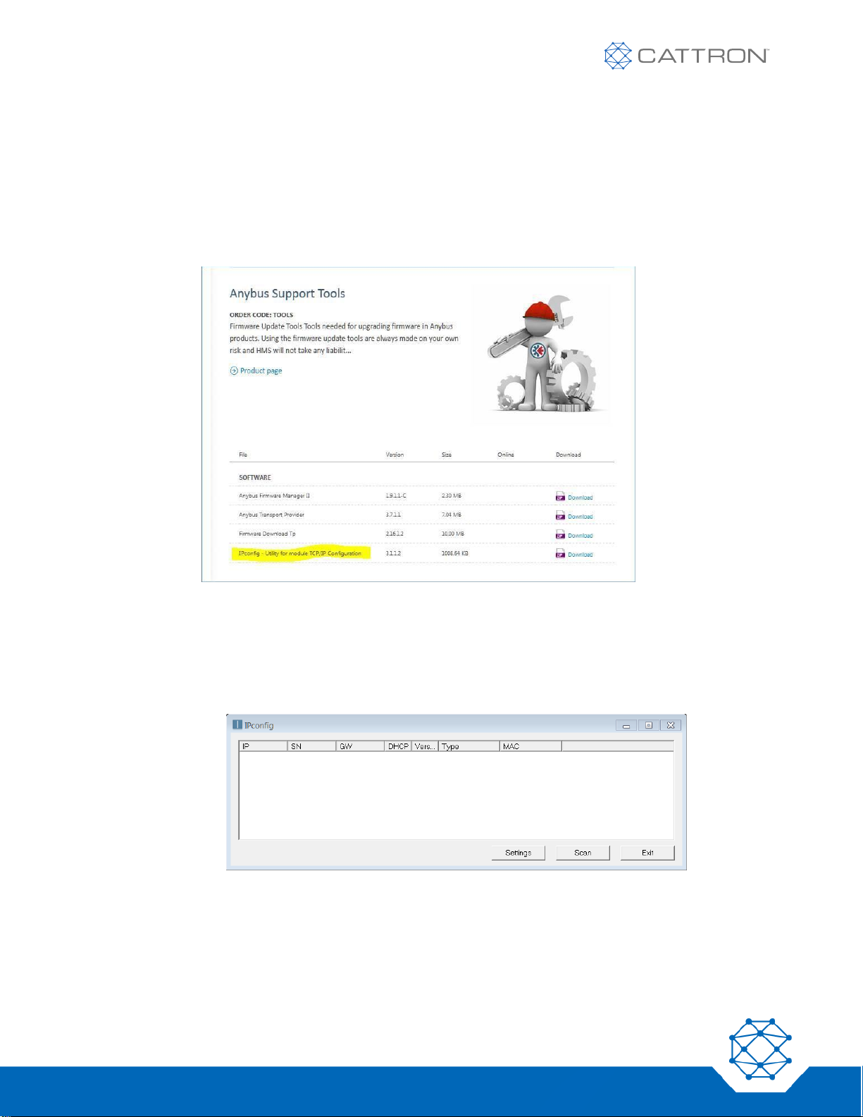
To program the IP address on an MSD it is first necessary to download a third-party tool which is freely available
from HMS, the manufacturer of the Anybus EtherNet modules used in the MSD.
a. To download and install the IPconfig software tool onto your PC follow this link:
https://www.anybus.com/support/file-doc-downloads/anybus-support-tools?orderCode=tools
Figure 17: Anybus download webpage
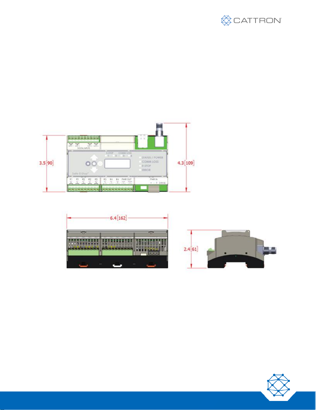
b. Connect your PC to the sameLAN the MSD is connected to. They do not need to be configured to the
same subnet.
c. Start the tool. A simple window will open.
Figure 18: IP Configuration Window
d. Press the Scan button. All devices using Anybus EtherNet interface will be detected and shown.
e. Double-click on the device you wish to configure and a new window will appear where you can set all IP
parameters (IP address, subnet mask, gateway, etc.)
f. The MSD’s current setting can be reviewed on the IP address screen
Page 44

44
Version 17
Safe-E-Stop™
User Guide
8.6.1 Ethernet Telegram Content
NOTE: The MSD’s Ethernet interface is NOT designed to be used for safety-critical applications. It is exclusively a
system status and information mechanism.
The MSD is offered with three different physical BUS configurations, these are;
1. No bus fitted
2. EtherNet/IP (also supports Modbus TCP)
3. PROFINET (also supports Modbus TCP)ETHERNET/IP AND MODBUS TCP, THE 2
ND
SUPPORTING PROFINET AND
MODBUS TCP, AND THE 3
RD
WITH NO ETHERNET
NOTE: REFER TO APPENDIX FOR TELEGRAM MAPPING INFORMATION
8.7 MSD Operation
The MSD is a critical part of your machine control system. For reliable operation, it is important that it is operated
within designed limits as directed and is maintained in good order.
As long as the MSD remains powered on, the only interaction that may be required will be the result of one or
more PSDs leaving RF range, resulting in communication loss for longer than 30 seconds. This condition requires
the remaining users to confirm that the user of the offending PSD was not subject to an accident. To enforce this
check, all PSDs will automatically unlink and the MSD will require its COMM LOSS RESET button to be pressed
as a confirmation before any PSDs are able to re-link.
The reset button is wired into one pair of the MSD's safety inputs, enabling the button to be placed at a
convenient location near the operators.
8.8 MSD Installation
8.8.1 Safety Instructions for Installation
Only trained and qualified persons may perform installation and maintenance work.
NOTE: Ensure suitable and appropriate transient protection devices are fitted to the relay’s contacts. Ensure
correct wiring of the machines’ main contactors and reset circuits. Use appropriate gauge wiring and
under no circumstances use wire of less than 24AWG. Ferrules should be used to protect against loose
wire strands and proper insertion into the terminals. Thoroughly test each hard-wired and
Safe-E-Stop MSD prior to handing over to production.
▪ Isolate the system from the electrical power in accordance with the applicable regulations.
▪ Observe user-specific regulations.
▪ Only use suitable tools.
▪ Secure the installation area.
8.8.2 MSD Installation Notes on Enclosure
The MSD must be housed in a secondary enclosure for protection; a suitable option kit (2OPT-8637-A102) is
available from Cattron. This enclosure provides visibility to the MSD. This allows local users to better understand
Page 45
45
Version 17
Safe-E-Stop™
User Guide
its operational status by reference to the MSD LEDs and LCD. All required information can also be obtained
through the Ethernet port.
In any case, the enclosure must provide an appropriate protection level for the environment in which it is installed
and also maintain the MSD within its stated operating parameters (see appendix).
The enclosure should provide suitable mechanical rigidity, IP rating, etc. The wiring should carry a suitable rating
for voltage, current, insulation, temperature rating, etc.
It is suggested that an enclosure approved for use by a recognized authority, such as UL, CSA, Intertek, TUV,
etc., be selected. The optional enclosure (Cattron Part Number 2OPT-8637-A102) provides a suitable level of
protection for most generic industrial and commercial environments.
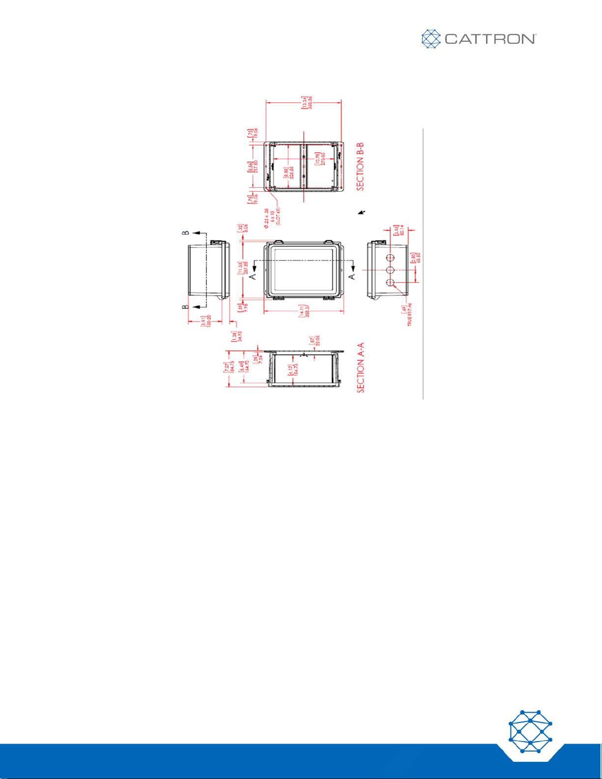
8.8.2.1 MSD Dimensions
Figure 19: MSD Dimensions
Page 46
46
Version 17
Safe-E-Stop™
User Guide
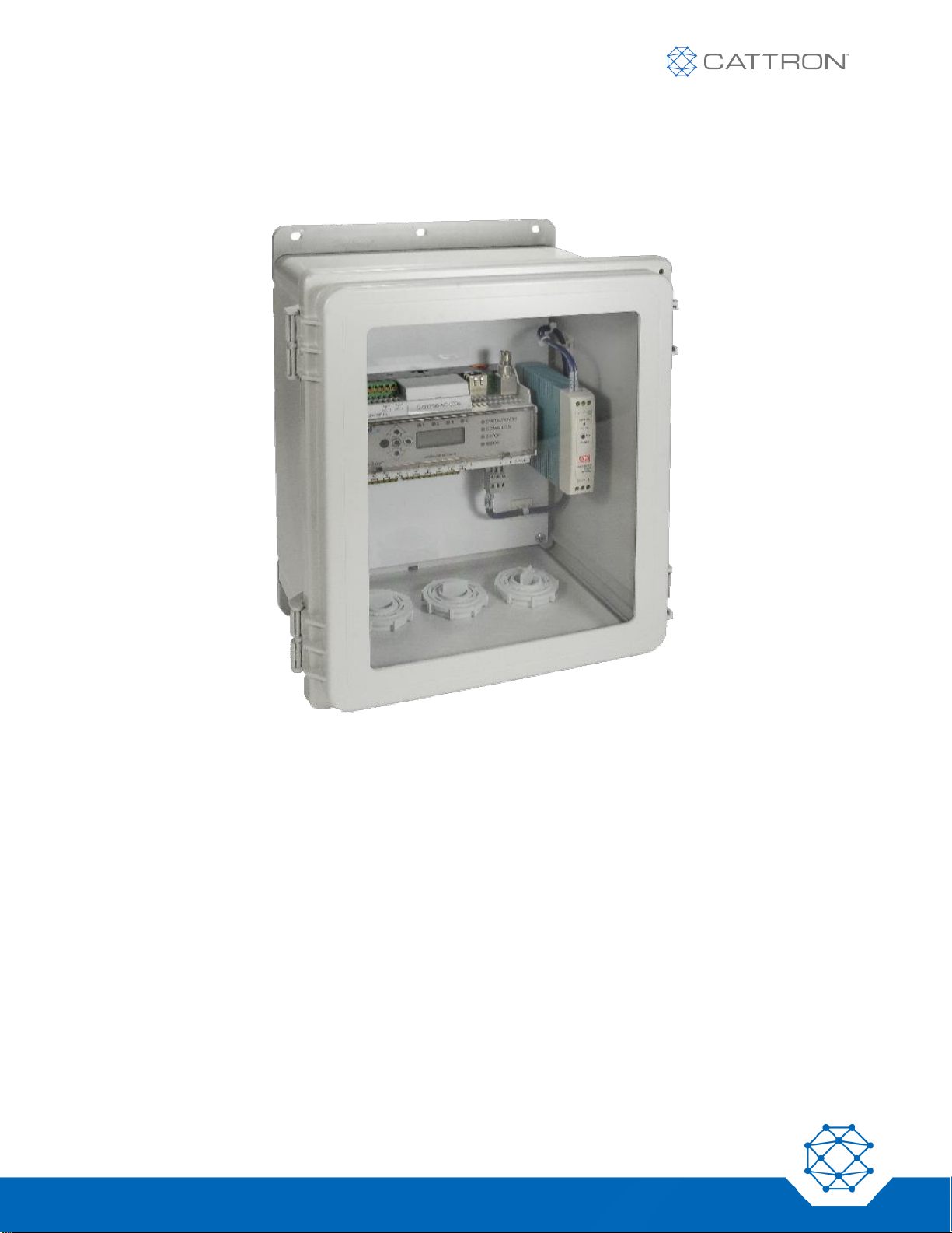
8.8.2.2 Secondary Enclosure Option Kit (2OPT-8637-A102) Dimensions
Figure 20: Secondary Enclosure Dimensions
Page 47
47
Version 17
Safe-E-Stop™
User Guide
The secondary enclosure kit comprises the enclosure, an internal backplate with DIN rail mounted, and three
25mm conduit connection points: one for the antenna and two for the remainder of the wiring.
Metallic conduit must be bonded together and grounded. The backplane must also be grounded if a 110Vac
supply is used or switched by the MSD.
Figure 21: MSD Optional Secondary Enclosure and Power Supply
8.8.3 General Rules for Mounting the MSD
The MCU is designed for DIN rail mounting, is rated at IP30, and must be protected from moisture and dust.
Mount the MCU on a DIN rail in a secondary enclosure (see 8.8.2) (a suitable option kit is available from
Cattron).
Select a location to minimize any possible interference from RF sources, such as motors. Ideally, install the MSD
enclosure close to the area where the hard-wired E-Stop is located and where it can be viewed easily by users
and maintainers. An approved enclosure with a window is ideal.
All wiring entering the enclosure must be terminated inside the enclosure.
To prevent interference on signal lines do not install high and low voltage cables in the same conduit.
The MSD ships with an external antenna kit. When installing the external antenna keep the antenna cable
separate from all other wiring, both inside and outside the secondary enclosure.
If the MSD is in a stand-alone application i.e. not being used with a PLC, it will be necessary to also have a
suitable DIN rail-mounting 24Vdc power supply (an option available at the time of order).
Page 48
48
Version 17
Safe-E-Stop™
User Guide
8.8.4 MSD Connections
Before installing the MSD, prepare an electrical wiring diagram that defines all electrical interface connections
between the system and the equipment being controlled.
Cattron also advises you to first read the following topics of discussion and to locate and refer to the example
mainline drawing provided.
Do not exceed the relay rating (see Appendix V). When connected to contactors, protect these relay contacts
with suitably-rated transient suppression devices to maximize contact life expectancy and prevent whiskering.
Overload protection <=8A for the relays and 1A for the power supply. Means to isolate the MSD from power when
required should be in place. The supply voltage is 24Vdc nominal (9-36Vdc), maximum current is 1A, nominal
current at 24V is 250mA. The MSD is fitted with a protective fuse next to the DC input terminal (Cattron part
number PRT-0001852) rated at 1A. An optional wide range (85-264VAC 47-63Hz 1A) power supply is available
from Cattron.
Care should also be taken to provide suitably-rated overload protection and isolation device. When using an
external power supply, this should also have a 1A overload protective device.
The safety inputs are rated at 24Vdc +- 4Vdc, omni-directional (non-polarized).
8.8.5 MSD Terminals
The MSD is fitted with spring clamp terminals to ensure reliable connections are continuously maintained.
These terminals require the use of a size 3 screwdriver to open the clamp for release (CAUTION, do not press the
release clamp too hard or it may damage the terminal). The ferrules are simply pushed in for insertion.
The use of ferrules is required to eliminate any possibility of wire strands shorting to adjacent terminals and to aid
insertion into the spring clamps.
8.8.5.1 Terminal and Wire Specifications
Wire sizes smaller than 0.459 mm2, 24AWG and a temperature rating of lower than 80° Celsius are unallowed, for
electrical safety certification compliance.
*For voltages greater than 24Vdc wire sizes of 18AWG (0.82mm2) minimum are recommended, but in all cases
the wiring must be correctly rated for its intended service,
Wire gauge: https://en.wikipedia.org/wiki/American_wire_gauge
Insulation: http://iq.ul.com/awm/stylepage.aspx?style=1015
Table 13: Terminals Maximum Wire Capacity
INPUTS AND OUTPUTS
POWER
IN
TEMPERATURE RATING
USE OF
FERRULES
Size mm2
0.459* to 1.5
0.459* to 2.5
>80°C (176F)
Required
Size AWG
24* to 16
24* to 12
>80°C (176F)
Required
Page 49
49
Version 17
Safe-E-Stop™
User Guide
8.8.6 Connecting the Antenna
Installation rules:
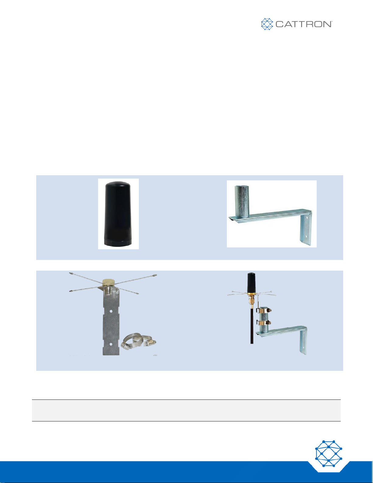
▪ Mount the antenna on the ground plane provided with the system. Loctite 262 or equivalent glue maybe used
on the thread to secure the antenna to the socket when necessary.
▪ The antenna should have a clear line of sight to the operating area and be within 300ft of all PSDs.
▪ The antenna extension (coaxial) cable must be no longer than required, being at most 50 feet in length
(without further reference to your supplier).
▪ Coaxial cable should be type RG58AU, similar or lower loss; appropriate cables are available from Cattron
and may have been provided with your system.
▪ If the coaxial cable is going to an antenna remote from the MSD location, keep it separate from any power-
carrying conductors and mount it within a metallic conduit system for protection.
▪ If the MSD is mounted within a secondary enclosure, correctly mount any metallic conduit with earth bonding
to the secondary enclosure.
Figure 22: Typical Antenna
Figure 23: Antenna Mount
Figure 24: Ground Plane (typical)
Figure 25: Typical Antenna Assembly
There are minor physical differences between these parts, depending on the RF Band.
NOTE: Cable type may vary depending on required cable length; standard 25ft and custom-length cables are
available from Cattron.
Page 50

50
Version 17
Safe-E-Stop™
User Guide
9. System Commissioning
When the system has been installed, the functionality should be tested thoroughly as follows:
1. Charge the PSDs.
2. Verify that the MSD is in a protective secondary enclosure suitably rated for the environment.
3. Inspect all wiring to ensure it is correct, secure, and neatly restrained according to good engineering
practice and compliant with all local and national rules.
4. Any metallic conduit that was used should be suitably cross bonded when connecting to a
non-metallic enclosure.
5. Verify that appropriate supply protection has been installed to the MSD.
6. Verify that the correct operating voltage is being applied, 24Vdc to the MSD, and that the polarity is
correct; higher voltages require the optional power supply.
7. Verify that the MSD reset switch has been installed and is accessible to the operators.
8. Verify that the antenna is mounted correctly and in such a way that it has good line of sight to the
operating area and that the cables are secure.
9. Apply power and observe that the MSD powers up correctly and the LCD is displaying ‘LINKED
PSD NONE.’
10. Verify that the machine can be started as normal.
11. Verify that each of the existing fixed E-Stop switches still operate correctly.
12. Link each of the PSDs in turn. Verify that each links correctly and operates the E-Stop correctly.
13. Ensure operators are trained in the use and features of the system, particularly in the use of the battery
charger, logging on and logging off requirements, activation and release of the E-Stop switch, use of the
belt clip, and understanding the operating range and consequences of exceeding the operating range,
use of the MSD reset switch in the event of a prolonged communication loss, and expectations to
maintain the equipment in good operating order.
Page 51

51
Version 17
Safe-E-Stop™
User Guide
10. System Decommissioning
If the system is to be decommissioned it is important to ensure that the machine is left in a fully operational state
and that any hard-wired E-Stop switches are fully functional. Decommissioning must be carried out by competent
and trained personnel. Equipment removed should be disposed of in compliance with local and national rules
related to disposal and recycling of electronic equipment and batteries.
Page 52
52
Version 17
Safe-E-Stop™
User Guide
11. Parts Lists
11.1 Part Numbers
The following part numbers must be specified with the RF Band letter in place of the ‘X1’ according to the
following frequency chart. If you are unsure of the band you require, contact Cattron or your authorized distributor
for advice.
Table 14: Frequency Chart for Part Number Matrixes
RF BAND
FREQ MHZ
WHERE TYPICALLY USED
A
418-419
China
B
428-434
EU, Brazil & others
C
447
EU Licensed
D
450-470
North America and Other licensed
E
869
EU F 902-928
North America
J
429
Japan
Table 15: MSD & PSD Part Numbers
ITEM
PART NUMBER
DESCRIPTION
PSD
PSD-2-X-C
PSD, must identify band (X) Color (C) and serial number of
target system if ordered after main system.
MSD
MSD-2-X-Y
MSD, must identify band (X) Bus option (Y) and serial number
of target system if ordered after main system
Refer to 2.19 for full details of configuration parameters.
Table 16: Antenna Kit Contents
PSS VERSION
1&2
BANDS
COVERED
ANTENNA
ANTENNA MOUNT
GROUND
PLANE
CO-AXIAL
CABLE 25FT
(7.7M)
ORDERING NUMBER EXAMPLE - Items Included
PSA
- 2 -
ABJ 1 1 1 1
PSA
- 2 -
CD 1 1 1 1
PSA
- 2 -
EF 1 1 1 1
Page 53
53
Version 17
Safe-E-Stop™
User Guide
Table 17: Accessory Part Numbers
ITEM
PART NUMBER
DESCRIPTION
MSD Secondary Enclosure
kit
2OPT-8637-A102
Enclosure IP66, NEMA 4, Clear hinged locking lid with
DIN rail with 3 Cable glands
Power Supply 100-264Vac to
24Vdc 1A DIN Rail mount
2OPT-8637-A103
Power supply 110Vac – 24Vdc
PSD Belt Clip
1PRT-8795-A001
PSD Belt Clip Back mount open face
Battery Charger Single Slot
1PRT-8778-A001
PSD Two-hour Battery Charger 110v-240Vac Single Slot
Battery Charger Six Slot
1PRT-8779-A001
PSD Two-hour Battery Charger 110v-240Vac Six Slot
Label sheet, multi-color logo
3LBL-8777-A101
Label sheet with 6 different color replacement logos for
easy identification of the PSD
MSD Fuse
PRT-0001852
Fuse, Ceramic, 1.5A
User Manual V2, English
9M02-8978-A001-EN
Installation and operation manual
User Manual V2, German
9M02-8978-A001-DE
Installation and operation manual
User Manual V2, Portuguese
9M02-8978-A001-PT-BR
Installation and operation manual, Brazilian
User Manual V2, French
9M02-8978-A001-FR
Installation and operation manual, European
User Manual V2, Spanish
9M02-8978-A001-ES-MX
Installation and operation manual, Mexican
Table 18: Example MSD & PSD Part Numbers
PSS PART NUMBER
DESCRIPTION
PSD-2-B-R
PSD version 2, for Band B (433-434), Red
PSD-2-F-Y
PSD version 2, for Band F (902-927), Yellow
PSD-2-D-G
PSD version 2, for Band D (450-470), Green
PSD-2-J-K
PSD version 2, for Band J, Black
MSD-2-D-X
MSD version 2, for Band D, No Bus
MSD-2-B-P
MSD version 2, for Band B, PROFINET bus
MSD-2-D-E
MSD version 2, for Band D, EtherNet/IP bus
Table 19: Example Parts needed to build a System
PART NUMBER
QTY
DESCRIPTION
COMMENT
PSD-2-B-R
7
PSD version 2, for Band B (433-434), Red
Maximum of 15
MSD-2-B-P
2
MSD version 2, for Band B, PROFINET bus
One plus one spare
PSA-2-AB
1
Full Antenna Kit, Bands A and B
One needed per installation
1PRT-8779-A001
1
Battery Charger Six Slot
As needed
2OPT-8637-A102
1
MSD Secondary Enclosure kit
If not in client’s enclosure
2OPT-8637-A103
1
Power Supply 100-264Vac to 24Vdc 1A DIN Rail mount
If no 24Vdc is available
3LBL-8777-A101
7
Label sheet, multi-color logo
If another color logo is wanted.
9M02-8681-A001-FR
1
User Manual, French
Page 54

54
Version 17
Safe-E-Stop™
User Guide
12. Maintenance
The Safe-E-Stop personal safety system is a safety-critical device that is designed, built, and maintained to the
strictest of standards. There are no user-serviceable parts within either the PSD or MSD.
For any repairs that may be required to these units, return to Cattron or an authorized service agent is required.
12.1 PSD Maintenance
Each time the PSD is put into operation, examine it for any obvious physical damage that may affect safe and
reliable operation. When switching on the unit, verify that the status LED, LCD, and haptic feedback
all work.
Your PSD battery will slowly degrade over time; by the time it has been charged and discharged 500 times it
will have lost approximately 20% of its capacity. Cattron therefore recommends that you calculate your usage so
that you can determine when the battery will need to be replaced and plan to ship the PSD back for service at that
point in time.
The PSD must remain in good physical condition and operated within its specified limits. The enclosure sealing
is carefully maintained by tamper proof screws set at a critical torque setting.
If any physical damage that may compromise the sealing of the enclosure or operational performance is apparent
on the PSD, return it for repair.
The PSD may be cleaned with warm soapy water using common dish washing soaps. Stubborn stains may be
removed with a cloth dampened with isopropyl (rubbing) alcohol.
Do not use:
▪ Heavy industrial cleaners
▪ Citrus or oil-based cleaners
▪ Ethanol (denatured alcohol, methylated spirits)
▪ Acetone and acetone-based cleaners
▪ Chlorine based cleaners (bleach)
Do not store your PSDs at elevated temperatures.
Page 55

55
Version 17
Safe-E-Stop™
User Guide
12.2 MSD Maintenance
The MSD must remain in good physical condition and must be operated within its specified limits. The enclosure it
is mounted within must be rated for the environment and the inside of this enclosure kept free of condensation.
Cable and conduit entry points must be kept in good condition.
If the MSD is damaged or faulty, return it to Cattron or an authorized service agent for repair.
If the enclosure housing the MSD is damaged, it should be repaired to prevent damage to the MSD.
The MSD should not need cleaning if it has been installed in a secondary enclosure according to this manual.
Dust may be removed with a dry cloth or by the use of a light air jet or vacuum.
If the MSD fails to power on (No LEDs or display), verify that the incoming supply is correct on the 24V incoming
connector first. If this is correct there should be 24Vdc between P4 terminals 7+8 and 9+10. If missing, F3
adjacent to the incoming power terminal may be faulty. As the MSD may have more than one source of power on
its terminals, isolate if necessary. After removing power from the MSD, F3 can be removed by carefully pulling the
fuse straight out using tweezers or needle nose pliers. Replacement is the reverse of the removal procedure. F3
is a 1.5A, 125V slow blow ceramic fuse, Cattron part number PRT-0001852.
No further maintenance of the MSD is possible.
12.3 Spare MSD
A configured spare MSD may be included in an installation for rapid recovery in case of a problem, if so, it is
critical that only one MSD can be powered at any time, this could be achieved with a power change over Keyswitch.
The outputs and reset inputs can normally be wired in parallel.
Note that the Antenna system will also either need to be duplicated on the spare, or the coaxial cable switched to
the operating unit.
Page 56
56
Version 17
Safe-E-Stop™
User Guide
Appendix A: PSD and MSD Configuration
A.1 General
The Configuration tool makes it possible for any user to set the operating frequency of a PSD or an MSD. It also
allows authorized users such as major users and distributors to set the MSD and PSD master address, plus the
PSD’s individual sub-address.
Address setting uses an online database and is restricted to authorized users to ensure no address or subaddress duplication can exist, as this could present a safety issue.
A.2 Benefits of using the configuration tool
Frequency Change
The Safe-E-Stop system must have an interference-free operating RF channel to reliably maintain a machine in
the running state, as interference could block the signal and lead to false E-Stop events. Having the configuration
tool makes it possible for a user to change the operating frequency in the event that another system on or off site
is causing interference on the current channel. It also means that for authorized users, spare PSDs and MSDs
can be stored and deployed quickly for any user on any machine, leading to much faster service.
WARNING
Selection of the correct operating frequency is entirely the responsibility of the user. Cattron accepts no
responsibility for incorrect frequency selection or configuration.
The frequency selected must conform to the channel-setting rules shown in section 4 of this manual or the
system may not function correctly.
For licensed frequencies, the channel set must also have a valid FCC, IC, or other license, or the user may be
subject to federal license infringement fines.
Master Address Change
The Safe-E-Stop system requires that the MSD and associated PSDs all share a common master address.
Having the configuration tool makes it possible for an authorized user to set or change the master address of any
MSD or PSD, allowing for spare PSDs and MSDs to be stored and deployed quickly for any user on any machine,
leading to much faster service. PSDs will also require the sub-address to be configured (see below).
WARNING
Users should ensure that when a system includes one or more spare MSDs, that only one is powered on at a
time or the system will not operate without errors.
All users must ensure that only one Master Address is used in one location, i.e. do not use one MSD and some
associated PSDs in one location and a spare MSD plus other associated PSDs in another location.
Authorized users must ensure the above is adhered to by associating only one Master Address per user
location.
PSD Sub-Address
MSDs can be associated with up to 15 PSDs, each having a unique identity between 1 and 15. This additional
PSD setting can be made with the configuration tool by authorized users.
Page 57
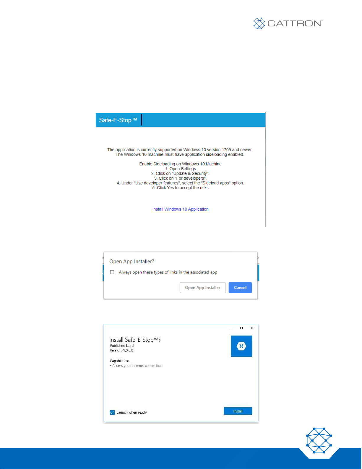
57
Version 17
Safe-E-Stop™
User Guide
A.3 Installing the Configuration Tool
The application should be installed on a PC with a Bluetooth® adapter. The PC must be running Windows 10
version 1709 or newer. The application can be downloaded from this link:
https://www.estopconfig.com/app
In order to install the application, it is necessary to allow side-loaded applications as described on the opening
page.
If prompted, select ‘Open App Installer’.
Follow the installation instructions.
Page 58
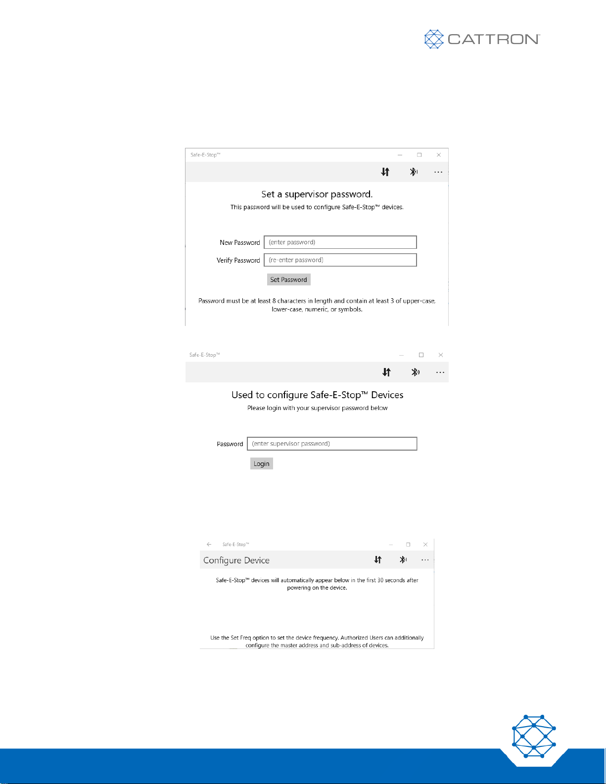
58
Version 17
Safe-E-Stop™
User Guide
A.4 Using the Configuration Tool
Launch Application
Launch the application and set the supervisor password. Note that if this password is lost, the application will
need to be re-installed.
Log in.
Configuring Devices (Frequency)
The configure device screen will appear. Power up the PSD or MSD.
Page 59
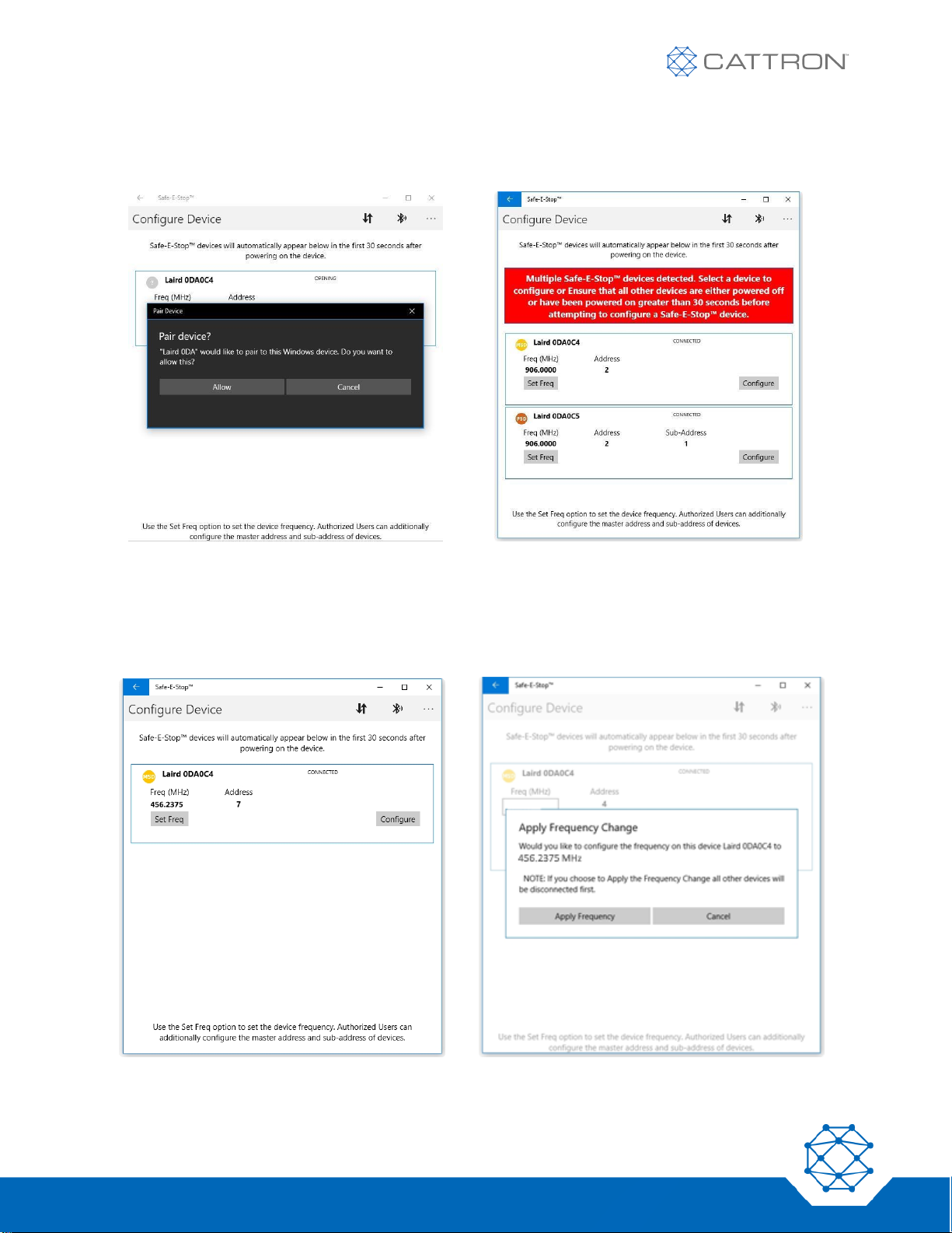
59
Version 17
Safe-E-Stop™
User Guide
Select the device from the list shown and pair with it.
If multiple devices have been powered on (or have reset) in the last 30 seconds, be sure to select the correct
device.
To set the frequency, click on the ‘Set Freq’ box, enter the new value (compliant with the frequency setting
rules of section 4 of this manual) and click ‘Apply’.
A confirmation box will appear. Click ‘Apply Frequency’ to continue.
Page 60
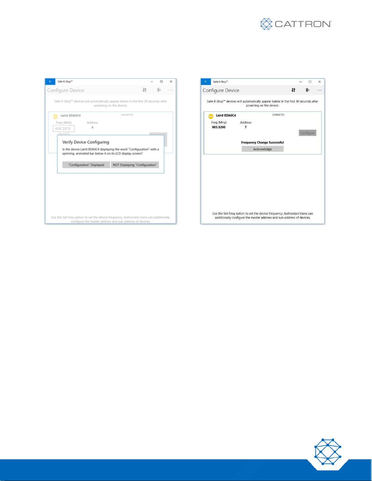
60
Version 17
Safe-E-Stop™
User Guide
● A ‘Verify Device Configuration’ box will appear asking you to check the PSD or MSD to ensure the
device is showing a changed configuration message.
● If successfully applied, a confirmation will appear. Click ‘Acknowledge’ to continue.
● Once the unit is powered on again, verify that it shows the expected configuration.
Page 61
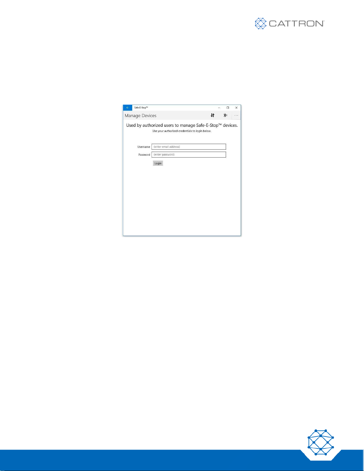
61
Version 17
Safe-E-Stop™
User Guide
Configuring Devices Authorized Users (Frequency or Address)
Configuration of address requires that the PC is connected to the internet so that login to the online address
management database and authorized user management is available.
User login information will have been pre-assigned by Cattron.
If this page is not visible, it can be switched to by clicking the arrows icon next to the Bluetooth icon.
Once authorization has been obtained, the MSD and PSD can be programmed while the PC is no longer
connected to the internet.
Once the user is logged in, a ‘Manage Devices’ screen will appear with three available tabs at the top:
● Available (devices)
● Authorized (devices that can now be configured offline)
● Destroyed (devices that have been destroyed and the address released for use again)
Note that for address configuration,
● Master Address will be restricted to
o 3 MSDs (1 primary and 2 spares)
o 15 PSDs
● 15 sub-addresses (each of A through O) will be restricted to
o 1 PSD
Page 62
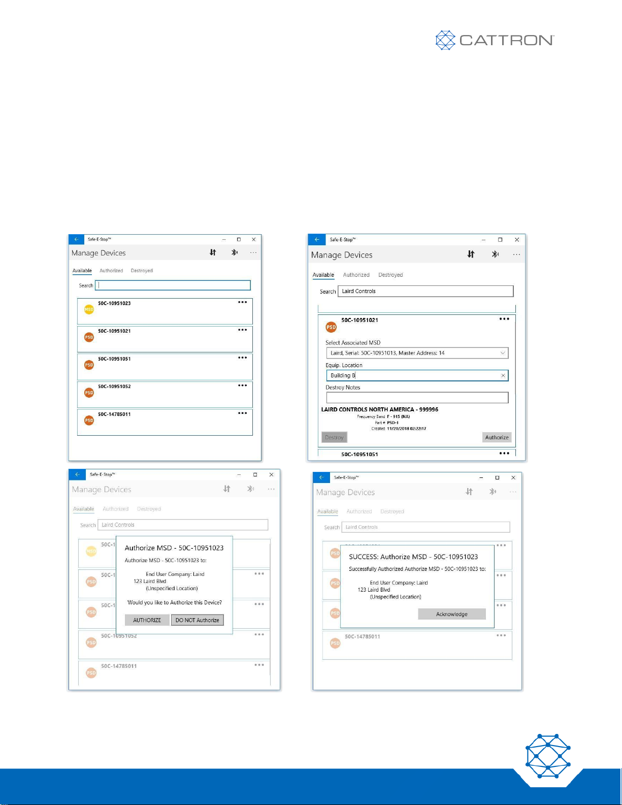
62
Version 17
Safe-E-Stop™
User Guide
Authorizing Devices
When a device is authorized, the master address and sub-address for PSDs will be automatically assigned.
Authorizing a Primary MSD
Unless an MSD is a spare, the ‘Make Spare’ selection should be left unselected.
When making a spare MSD or a PSD, see the next section first.
The ‘Available’ tab (left) will show a list of devices by type and serial number. Clicking on one of those devices
brings up the detailed information dialog (right) followed by the confirmation dialog to move it to the ‘Authorized’
tab.
Page 63
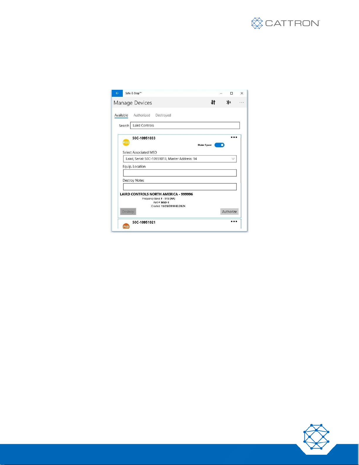
63
Version 17
Safe-E-Stop™
User Guide
Authorizing a Spare MSD
When making (authorizing) a spare MSD, it is necessary to select ‘Make Spare’ and then ‘Select Associated
MSD’ from the drop-down list on the Authorization tab (below left). This ensures that both units share the same
master address.
Authorizing a PSD
When making (authorizing) a PSD, it is also necessary to ‘Select Associated MSD’ from the drop-down menu on
the ‘Authorization’ tab. (Remember that the master address is the common factor and there may be up to three
MSDs with the same master address; it will not matter which is selected. This ensures that both the MSD and
PSD share the same master address.) The system will automatically assign the next available sub-address.
Page 64
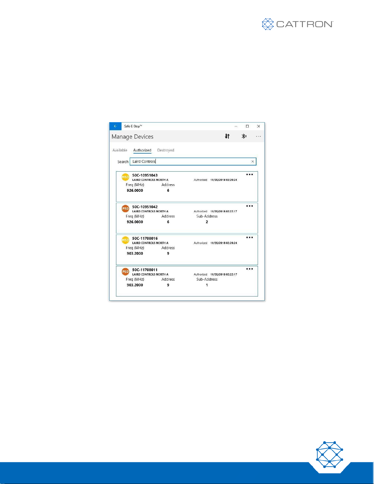
64
Version 17
Safe-E-Stop™
User Guide
Applying Configuration to a unit
● Once the required units are on the ‘Authorized’ tab, the PC can be taken offline if necessary to
program the specific unit (by serial number, e.g. 50C-12011023) requiring configuration.
● The process is somewhat like programming the frequency above. The frequency will be the only
parameter that must be entered manually for the frequency determined for use on this system. The
address parameters will be pre-defined during configuration.
● Only devices on the ‘Authorized’ tab can be configured.
Page 65
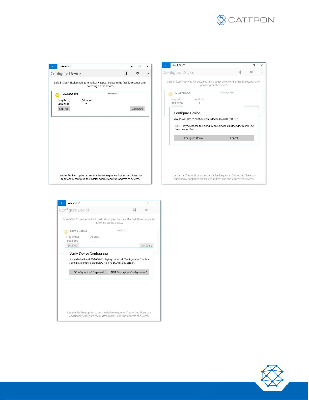
65
Version 17
Safe-E-Stop™
User Guide
● Click the Bluetooth icon at the top of the screen.
● then switch it on. It will show on the screen (below left).
● Click the ‘Configure’ button and confirm as prompted.
Page 66
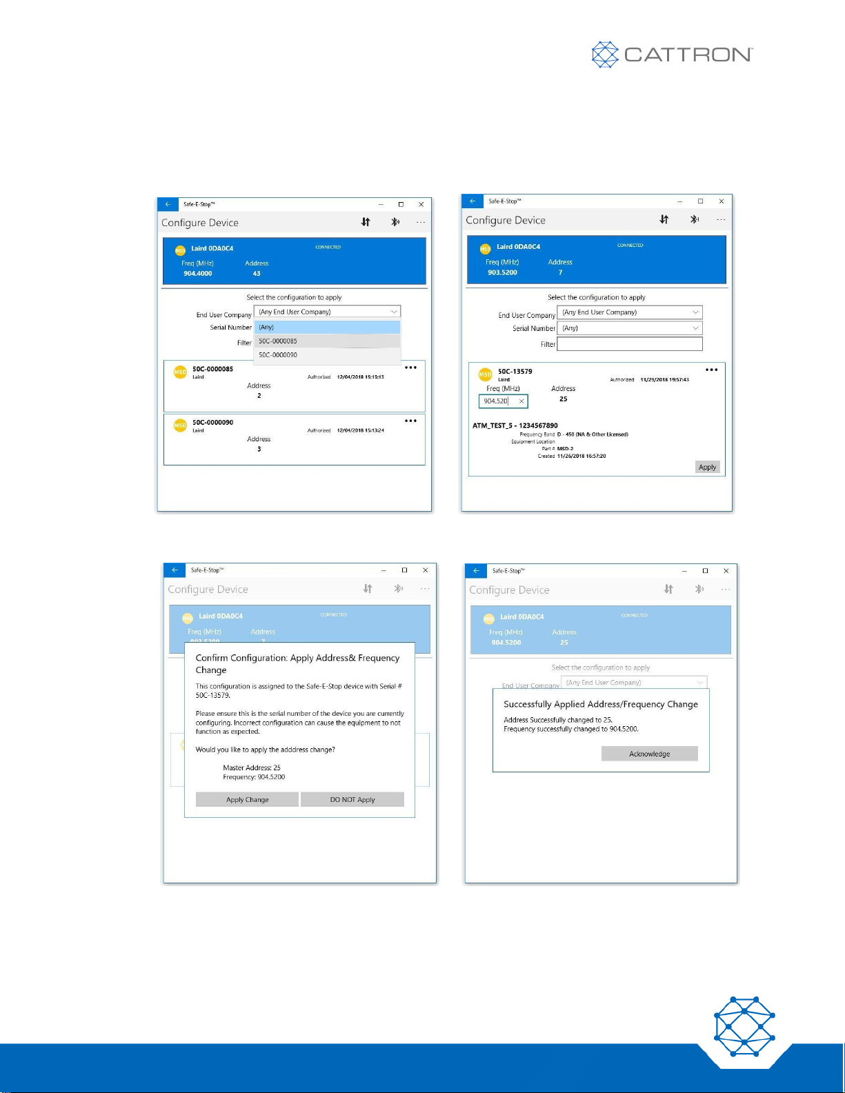
66
Version 17
Safe-E-Stop™
User Guide
● Select the correct device configuration from the available devices. It is possible to click the ‘End User
Company’ drop-down and choose the correct serial number, or click the ‘Serial Number’ drop-down
and select the correct serial number to match the device to be programmed.
● Enter or correct the operating frequency as required.
● Click ‘Apply’, then approve the requests to confirm and acknowledge when complete.
● Verify that the unit shows the expected configuration when powered on again.
Page 67
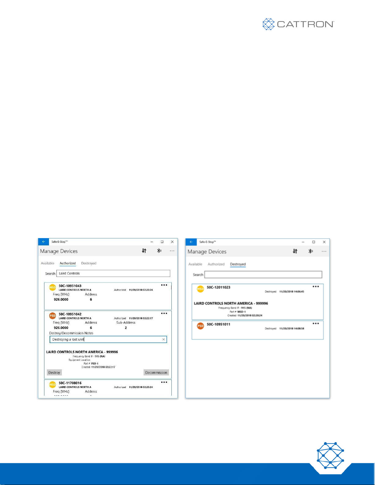
67
Version 17
Safe-E-Stop™
User Guide
De-commissioning and marking units as Destroyed
Decommissioning a unit
If a unit is no longer required on a given system, it can be decommissioned and made available again for use on
another system.
This can be achieved by selecting units from the ‘Authorized’ tab and clicking the ‘Decommission’ button. Confirm
and acknowledge as prompted.
The device will then appear on the ‘Available’ tab.
Decommissioning disassociates a serial number from any system and releases the address allocated to that unit.
Marking a unit as Destroyed
If a unit is definitely lost or damaged beyond repair, its address can be made available to use again on a new unit.
This is an important step, as there are strict limits on the number of units that can be assigned to a master
address. Only 15 PSD sub-addresses can be issued per master address.
Marking a unit as destroyed can be achieved by selecting units from the ‘Authorized’ tab, adding a reason in the
‘Destroy/Decommission Notes’ field, and clicking the ‘Destroy’ button. Confirm and acknowledge as prompted.
These devices will then appear on the ‘Destroyed’ tab.
NOTE: Destroyed units cannot be returned to an available state.
Marking a unit as Destroyed deletes its serial number from the database and makes its address allocations
available for use.
Page 68
68
Version 17
Safe-E-Stop™
User Guide
Appendix B: RF Channel Number vs Operating Frequency
Operating frequency must be assigned in compliance with the rules set out in each RF band section below.
Frequency is factory set, so at time of order, the factory must be advised which RF channel should be selected
based on knowledge of existing RF systems that are already operating on site.
Band B (433-434MHz)
This band starts at 433.0775MHz. Channel spacing is 25KHz.
There are 69 channels available and channel frequency is coded with a letter and two digits.
Channel A00 will be 433.0775MHz. Channel A68 will be 434.7775MHz.
Band B Channel Spacing Rules
If the MSD is to be installed less than 100m (330’) from another RF system (Cattron or other), select a frequency
at least 50KHz (2 channels) away from other frequencies in use.
Band D (450-470MHz)
This band starts at 450.000MHz. Channel spacing is 12.5KHz.
There are 1600 channels available and channel frequency is coded with a letter and two digits.
Channel A00 will be 450.000MHz. Channel B00 will be 451.250MHz. Channel Q00 will be 470.000MHz.
Band D Channel Spacing Rules
If the MSD is to be installed less than 100m (330’) from another RF system (Cattron or other), select a frequency
at least 50KHz (4 channels) away from other frequencies in use.
Band F (902-927MHz)
This band starts at 902.6MHz. Channel spacing is 100KHz.
There are 349 channels available and channel frequency is coded with a letter and two digits.
Channel A00 will be 902.6MHz. Channel B00 will be 912.600MHz. Channel C49 will be 927.500MHz
Band F Channel Spacing Rules
If the MSD is to be installed less than 100m (330’) from another RF system (Cattron or other), select a frequency
at least 200KHz (2 channels) away from other frequencies in use.
Table 20: Unavailable Frequencies
AVOID FREQUENCIES
Band B
Band D
Band F
434,177,500
466,937,500
902,600,000
912,100,000
921,600,000
902,700,000
912,200,000
921,700,000
902,800,000
912,300,000
921,800,000
902,900,000
921,100,000
921,900,000
911,700,000
921,200,000
922,000,000
911,800,000
921,300,000
922,100,000
911,900,000
921,400,000
912,000,000
921,500,000
Page 69

69
Version 17
Safe-E-Stop™
User Guide
Band J (929MHz)
This band starts at 429.250MHz. Channel spacing is 25KHz.
There are 40 channels available and channel frequency is coded with a letter and two digits.
Channel A00 will be 429.250Hz. Channel A39 will be 429.7375MHz.
Band J Channel Spacing Rules
If the MSD is to be installed less than 100m (330’) from another RF system (Cattron or other), select a frequency
at least 50KHz (2 channels) away from other frequencies in use.
Page 70

70
Version 17
Safe-E-Stop™
User Guide
Appendix C: Approvals and Compliance Notifications
FCC Caution
This device complies with part 15 of the FCC Rules. Operation is subject to the following two conditions: (1) This
device may not cause harmful interference, and (2) this device must accept any interference received, including
interference that may cause undesired operation.
EU Caution
Hereby, Cattron, declares that the Safe-E-Stop™ system follows the essential requirements and other relevant
provisions of Directive 2014/53/EC.
Equipment Rating
The PSD is rated at IP67 and an operating temperature range of -20°C to +60°C; do not use the PSD for
conditions beyond these limits.
The PSD battery cannot be charged if its temperature exceeds 40°C.
The MSD is rated at IP30 and an operating temperature range of -20°C to +60°C, up to 90% non-condensing RH.
For environments harsher than this, use an appropriate secondary enclosure.
Declaration of Conformity
Declaration of Conformity can be located at www.cattron.com/doc
Page 71
71
Version 17
Safe-E-Stop™
User Guide
Appendix D: Ethernet Configuration & Data Mapping
EtherNet/IP
Table 21: Configuration Parameters for the EtherNet/IP Telegram:
PARAMETER
ASSEMBLY INSTANCE
SIZE (IN BYTES)
Input (T->O)
100
64
Output (O->T)
150
64
Configuration
3
0
Table 22: EtherNet/IP Device Identity information
CLASS: IDENTITY OBJECT (01H)
INSTANCES #1 ATTRIBUTES
#
Access
Name
Type
Value
1
Get
Vendor ID
UINT
1367 (Cattron)
2
Get
Device Type
UINT
12 (Communication Adapter Profile)
3
Get
Product Code
UINT
2
4
Get
Revision
Struct of:
Firmware revision number
Major Revision
USINT
(co-controller firmware revision, 1st segment)
Minor Revision
USINT
(co-controller firmware revision, 2nd segment)
5
Get
Status
WORD
Status summary of the device.
6
Get
Serial Number
UDINT
Serial number of HMS ABIC
7
Get
Product Name
SHORT_STRING
“Safe-E-Stop”
Table 23: Device Status (Attribute 5) – as Provided by the HMS ABIC
BITS
NAME
VALUE/ DESCRIPTION
0
Owned
1: Module has an owner
1
(Reserved)
Read as 0
2
Configured
1: Device has been configured (differently from out-of-the-box default)
3
(Reserved)
Read as 0
4-7
Extended Device Status
Supported values:
0: Unknown
2: At least one faulted I/O connection
3: No I/O connection established
4: Non-volatile configuration bad
6: At least one I/O connection in Run mode
7: At least one I/O connection established, all in idle mode
Other: (Reserved)
8
Minor recoverable fault
9 Minor unrecoverable fault
10
Major recoverable fault
11
Major unrecoverable fault
12-15
(Reserved)
Read as 0
Page 72
72
Version 17
Safe-E-Stop™
User Guide
Table 24: Input (to Remote Device) Data Mapping
BYTE #
FIELD
TYPE
DESCRIPTION / VALUE
1
Message Format Revision
USINT (0-255)
Revision of the Message Format Definition. Set to 1
2
Message Update Counter
USINT (0-255)
Free running counter; Increments each time the Ethernet/IP
message content is updated inside the MSD.
This is value is independent from the Ethernet/IP packet rate or
RF transactions rate.
3-4
System Address
UINT (0-65535)
5
MSD status:
Bit 0: ESTOP
Bit 1: COMLOSS
Bit 2: COMLOSS_
RESET
Bit 3: TILT
bit field:
BOOL
BOOL
BOOL
BOOL
Set to 1 when the MSD is in ESTOP state (a PSD ESTOP is
pressed or a PSD sends a TILT indication)
Set to 1 when the MSD is in COM LOSS state
Set to 1 when the MSD is in COM LOSS state and COM LOSS
recovery time expired is not expired yet
Set to 1 when a PSD TILT event is detected
6
PSD1 ID
USINT (0-255)
IDs of the PSD currently linked to MSD (up to 5 PSD)
0 : empty field
1-15 : PSD ID
16-255 : not used
7
PSD2 ID
Same
8
PSD3 ID
Same
9
PSD4 ID
Same
10
PSD5 ID
Same
11
Offending PSD ID
USINT (0-255)
PSD ID broadcasted by the MSD to all other PSDs after an
ESTOP or COMLOSS event, to be shown on the PSD displays.
0 : no PSD event (if MSD status is zero)
: MSD wired ESTOP button (if MSD ESTOP field is 1)
1-15 : Offending PSD ID
16-255 : not used
12
MSD display buttons
Bit 0: up arrow
Bit 1: down arrow
Bit 2: right arrow
Bit 3: left arrow
Bit 4: center button
Bits 5-7: Reserved
bit field:
BOOL
BOOL
BOOL
BOOL
BOOL
-
Each bit is Set to 1 when the corresponding button is pressed
Future use. Set to 0
13-16
Reserved
-
Future use. Set to 0
17
PSD1 – Status byte 1
Bit 0: TILT WARNING
indicator
Bit 1: REQUEST button
pressed
Bit 2: GREEN button – 2
nd
step
Bit 3: LOW RSSI indicator
Bit 4: LOW BATT
indicator
Bit 5: RELEASE button
pressed
Bit 6: Reserved
Bit 7: ESTOP pressed
bit field:
BOOL
BOOL
BOOL
BOOL
BOOL
BOOL
BOOL
Reflects PSD telegrams bits 31 to 38
18
PSD1 – Status byte 2
Bit 0-6: (FLP dependent)
bit field:
BOOL x 7
Reflects PSD telegrams bits 39-46
Page 73
73
Version 17
Safe-E-Stop™
User Guide
Bit 7: TILT indicator
BOOL
19
PSD1 – RSSI
SINT
(-128 to 127)
Received signal strength of last telegram received, in dBm
20-22
PSD2 Status bytes
1-2 & RSSI
(same structure as PSD1)
23-25
PSD3 Status bytes
1-2 & RSSI
(same structure as PSD1)
26-28
PSD4 Status bytes
1-2 & RSSI
(same structure as PSD1)
29-31
PSD5 Status bytes
1-2 & RSSI
(same structure as PSD1)
32
Reserved
Future use. Set to 0
33
MSD transactions counter
USINT (0-255)
Free running counter; increments each time a RF transaction is
initiated by the MSD.
34
PSD1 responses counter
USINT
Free running counters; each counter increment for each valid
response received from the corresponding PSD.
Valid responses are responses with right System Address and
no CRC or framing error
With the current transaction structure, if no response losses,
each PSD response counter increments twice as fast as the
MSD transaction counter
35
PSD2 responses counter
USINT
36
PSD3 responses counter
USINT
37
PSD4 responses counter
USINT
38
PSD5 responses counter
USINT
39-64
Reserved
Future use. Set to 0
Page 74
74
Version 17
Safe-E-Stop™
User Guide
Modbus TCP Configuration
The MSD implements a Modbus TCP server that provides access to the I/O Data.
The Modbus TCP server is available on both the EtherNet/IP and PROFINET versions.
● The server is accessible over TCP port 502
● Up to 8 simultaneous Modbus/TCP connections are supported
Table 25: Supported Function Codes
MODBUS FUNCTION
FUNCTION CODE
DESCRIPTION
Read Coils
1
Output Data Readback (discrete)
Read Discrete Inputs
2
Input Data Read (discrete)
Read Holding Registers
3
Output Data Readback (16-bit register)
Read Input Registers
4
Input Data Read (16-bit register)
Write Single Coil
5
Output Data Write (discrete)
Write Single Register
6
Output Data Write (16-bit register)
Write Multiple Coils
15
Output Data Write (discrete)
Write Multiple Registers
16
Output Data Write (16-bit register)
Mask Write Register
22
Output Data Modify (16-bit register)
Read/Write Registers
23
Output Data Write and Readback in a single operation (16-bit
register)
Table 26: Exception Codes
CODE
NAME
DESCRIPTION
01h
Illegal function
The function code received in the query is not supported
02h
Illegal data address
The data address received in the query is outside the initialized memory area
03h
Illegal data value
A value contained in the query data field is illegal
Page 75
75
Version 17
Safe-E-Stop™
User Guide
The Input registers follow the same structure as the EtherNet/IP messages, where the 64 bytes from the
EtherNet/IP messages are mapped to 32 Modbus 16-bit registers.
Table 27: Input Registers
MODBUS REGISTER
ADDRESS
MSB
LSB
REFERENCE: ETHERNET/IP
MESSAGES BYTES #
1
Registers mapping
Revision
Input Registers
Update Counter
1, 2
2
System Address MSB
System Address –
LSB
3, 4
3
MSD status
PSD1 ID
5, 6
4
PSD2 ID
PSD3 ID
7, 8
5
PSD4 ID
PSD5 ID
9, 10
6
Offending PSD ID
MSD display buttons
11, 12
7
(reserved)
(reserved)
13, 14
8
(reserved)
(reserved)
15, 16
9
PSD1 – Status byte 1
PSD1 – Status byte
2
17, 18
10
PSD1 - RSSI
PSD2 – Status byte
1
19, 20
11
PSD2 – Status byte 2
PSD2 - RSSI
21, 22
12
PSD3 – Status byte 1
PSD3 – Status byte
2
23, 24
13
PSD3 - RSSI
PSD4 – Status byte
1
25, 26
14
PSD4 – Status byte 2
PSD4 - RSSI
27, 28
15
PSD5 – Status byte 1
PSD5 – Status byte
2
29, 30
16
PSD5 - RSSI
(reserved)
31, 32
17
PSD1 responses
counter
PSD2 responses
counter
33, 34
18
PSD3 responses
counter
PSD4 responses
counter
35, 36
19
PSD5 responses
counter
(reserved)
37, 38
20 -32
(reserved)
(reserved)
39 – 64
Output Registers
32 output registers are implemented. No functions are defined for this release. Writing output registers have no
impact.
Page 76
76
Version 17
Safe-E-Stop™
User Guide
PROFINET Configuration
PROFINET protocol handling is done by a PROFINET communication module from HMS (Anybus-IC AB6005).
This module implements real-time (RT) PROFINET I/O in accordance with PROFINET Conformance Class A
(CC-A).
This module is pre-certified if using the default settings of all parameters and is using the original GSD (general
station descriptor) file provided by HMS. At this time, the PROFINET interface reflects HMS default values and
identifiers.
By default, the Anybus module identifies itself as a generic HMS product:
Table 28: Identity Information
PARAMETER
VALUE
Station Name
(not assigned)
Station Type
ABIC-PRT
Vendor ID
010Ch (HMS Industrial Networks)
Device ID
0008h (Anybus-IC PROFINET)
Electronic Data Sheet (GSD File)
The electronic data sheet (GSD file) is stored in XML format:
GSDML-V2.3-HMS-ABICPRT-20130219.xml
The GSD file features the following characteristics:
● Three Device Access Points (DAP):
- ABIC_V1 : RT Migration for older firmware.
- ABIC_V15 : RT Migration. Supplied for reverse compatibility with IO Controllers not supporting
extended PROFINET diagnostics
- ABIC_V2 : RT Standard
● All DAPs support modules with following block sizes: 1, 2, 4, 8, 16, 32, 64, 128 bytes
● All modules available as input, output and bidirectional (input/output)
● Each module is associated with exactly one submodule.
In most cases, ABIC_V2 DAP should be selected, with 64 bytes input module.
Input Data
Input Data size : 64 bytes
Table 29 Input (to Remote Device) Data Mapping
BYTE #
FIELD
TYPE
DESCRIPTION / VALUE
1
Message Format Revision
USINT (0-255)
Revision of the Message Format Definition. Set to 1
2
Message Update Counter
USINT (0-255)
Free running counter; Increments each time the Ethernet/IP
message content is updated inside the MSD.
This is value is independent from the Ethernet/IP packet rate or
RF transactions rate.
3-4
System Address
UINT (0-65535)
5
MSD status:
bit field:
Page 77
77
Version 17
Safe-E-Stop™
User Guide
Bit 0: ESTOP
Bit 1: COMLOSS
Bit 2: COMLOSS_
RESET
Bit 3: TILT
BOOL
BOOL
BOOL
BOOL
Set to 1 when the MSD is in ESTOP state (a PSD ESTOP is
pressed or a PSD sends a TILT indication)
Set to 1 when the MSD is in COM LOSS state
Set to 1 when the MSD is in COM LOSS state and COM LOSS
recovery time expired is not expired yet
Set to 1 when a PSD TILT event is detected
6
PSD1 ID
USINT (0-255)
IDs of the PSD currently linked to MSD (up to 5 PSD)
0 : empty field
1-15 : PSD ID
16-255 : not used
7
PSD2 ID
Same
8
PSD3 ID
Same
9
PSD4 ID
Same
10
PSD5 ID
Same
11
Offending PSD ID
USINT (0-255)
PSD ID broadcasted by the MSD to all other PSDs after an
ESTOP or COMLOSS event, to be shown on the PSD displays.
0 : no PSD event (if MSD status is zero)
: MSD wired ESTOP button (if MSD ESTOP field is 1)
1-15 : Offending PSD ID
16-255 : not used
12
MSD display buttons
Bit 0: up arrow
Bit 1: down arrow
Bit 2: right arrow
Bit 3: left arrow
Bit 4: center button
Bits 5-7: Reserved
bit field:
BOOL
BOOL
BOOL
BOOL
BOOL
-
Each bit is Set to 1 when the corresponding button is pressed
Future use. Set to 0
13-16
Reserved
-
Future use. Set to 0
17
PSD1 – Status byte 1
Bit 0: TILT WARNING
indicator
Bit 1: REQUEST button
pressed
Bit 2: GREEN button – 2
nd
step
Bit 3: LOW RSSI indicator
Bit 4: LOW BATT
indicator
Bit 5: RELEASE button
pressed
Bit 6: Reserved
Bit 7: ESTOP pressed
bit field:
BOOL
BOOL
BOOL
BOOL
BOOL
BOOL
BOOL
Reflects PSD telegrams bits 31 to 38
18
PSD1 – Status byte 2
Bit 0-6: (FLP dependent)
Bit 7: TILT indicator
bit field:
BOOL x 7
BOOL
Reflects PSD telegrams bits 39-46
19
PSD1 – RSSI
SINT
(-128 to 127)
Received signal strength of last telegram received, in dBm
20-22
PSD2 Status bytes
1-2 & RSSI
(same structure as PSD1)
23-25
PSD3 Status bytes
1-2 & RSSI
(same structure as PSD1)
26-28
PSD4 Status bytes
1-2 & RSSI
(same structure as PSD1)
Page 78
78
Version 17
Safe-E-Stop™
User Guide
29-31
PSD5 Status bytes
1-2 & RSSI
(same structure as PSD1)
32
Reserved
Future use. Set to 0
33
MSD transactions counter
USINT (0-255)
Free running counter; increments each time a RF transaction is
initiated by the MSD.
34
PSD1 responses counter
USINT
Free running counters; each counter increment for each valid
response received from the corresponding PSD.
Valid responses are responses with right System Address and
no CRC or framing error
With the current transaction structure, if no response losses,
each PSD response counter increments twice as fast as the
MSD transaction counter
35
PSD2 responses counter
USINT
36
PSD3 responses counter
USINT
37
PSD4 responses counter
USINT
38
PSD5 responses counter
USINT
39-64
Reserved
Future use. Set to 0
Output Data
Output Data size : 64 bytes
Data Mapping : Output Data content is not defined for this release. Writing output data has no impact.
Page 79

79
Version 17
Safe-E-Stop™
User Guide
Appendix E: Troubleshooting
Communication Losses
Repeated communication losses from random PSDs may be caused by one of four factors:
Required Operating Range is Too Long
Required operating range is beyond system capability within the operating environment. The system range will be
about 300ft (100m) line-of-sight to the MSD antenna, but when machinery and obstacles are interposed, this
range will be reduced. If operating range is too short even when line-of-sight is within the stated range, check the
next three items. In the case of a frequency-diversity (dual-channel) system, if both channels are less than solid,
check for common issues such as antenna, cable, and faulty equipment. If only one channel is below nominal,
look for interference issues.
Bad Antenna or Coaxial Cable
Check that the coaxial cable is securely attached at the MSD and at the antenna ground plane, and that the cable
is dry and undamaged. Also, check that the antenna is securely attached to the ground plane.
If the above are true, check the resistance of the coaxial cable at the MSD between center and screen:
▪ If it is short circuit, the cable is faulty.
▪ If it is open circuit, then short circuit the connector at the antenna end and make sure that the connector now
shows a short circuit at the MSD end. If not, the cable is faulty.
▪ If everything is OK, remove the short at the antenna end and reconnect the cable at both ends.
RF Interference
The PSS can only operate correctly in the absence of RF interference.
If RF interference is suspected, an audit of other wireless systems in the area should be conducted. If a problem
is found, remove the source of interference. Otherwise, the Safe-E-Stop system frequency will need to be
reprogrammed at Cattron or an authorized service facility.
NOTE: Use of licensed frequencies will normally provide a protected RF environment; use of unlicensed
frequencies will require careful onsite management to ensure reliable system operation.
MSD Radio is Faulty
If the items above have been eliminated as possibilities, the radio in the MSD may be faulty. This can be checked
by returning the MSD to Cattron for analysis and repair.
Page 80

80
Version 17
Safe-E-Stop™
User Guide
PSD
Error Light is Flashing
The error LED is flashing.
Wait until the PSD powers down after 3 minutes, then try restarting the unit. If the problem persists, return the
device to Cattron or an authorized service facility.
Error 1 Shown on LCD
The main controller has an error.
The PS remains in this state for 3 minutes, then turns off.
Return unit for service.
Error 2 Shown on LCD
The unit is unable to read the battery state.
Displays ERROR2 for 30 seconds and then turns off.
Unit pulses three times when the fault is initially detected.
The operator can unlink during this 30-second period to avoid a COMLOSS.
Return unit for service.
Error 3 Shown on LCD
The unit is unable to correctly read or decode the status telegrams for other PSDs or MSD.
Displays ERROR3 for 30 seconds and then turns off.
Unit pulses three times when the fault is initially detected.
The operator can unlink during this 30-second period to avoid a COMLOSS.
Return unit for service.
Battery Operating Time is Shorter than Expected
The PSD operates for 14+ hours on a fully charged battery at a temperature of around 20°C. Very low
temperatures will reduce this time; at temperatures below minus 20°C, operating time will be reduced by about
30%.
A battery that has been charged more than 500 times will have lost 20% of its capacity. This can be rectified by
having a new battery installed by Cattron or an authorized service facility.
Cannot Link to MSD
If 5 PSDs are already linked to the MSD, it will not be possible to link another PSD.
MSD Not Seen
A PSD and MSD must have matching configurations as identified on their displays. Check the configuration as
shown when the PSD and MSD are first turned on to ensure that they match. The MSD configuration is also
available on one of the LCD screen pages.
If other PSDs are successfully linked to the MSD and the configuration is correct, the PSD is faulty. Return to
Cattron or an authorized service facility.
Page 81

81
Version 17
Safe-E-Stop™
User Guide
Operating Range is Short
If all PSDs have the same issue, see the Error! Reference source not found section above. If only one PSD
has the problem, the PSD is faulty. Return to Cattron or an authorized service facility.
MSD
Error Light is Flashing
If switching the MSD off and back on does not resolve the problem, return to Cattron or an authorized service
facility.
No Power
If all lights are off, request the services of an authorized and trained service agent to conduct the following
analysis and repair:
Verify that the 24Vdc input supply is available and, if necessary, check and replace the fuse to the left of the
supply terminal.
If the fuse blows again, disconnect all input and output terminals and replace the fuse again. If the problem
persists, the MSD is faulty. Return to Cattron or an authorized service facility. If the fuse no longer blows, check
all external wiring for an intermittent short circuit on the 24V line and correct.
Operating Range is Short
If all PSDs have the same issue see Error! Reference source not found section above.
Cannot Reset Unit after a PSD Communication Loss
Check the wiring and voltages between the reset input, the external reset button, and the 24V supply to the reset
button. If this supply is not common to the MSD supply, ensure the 0v line of the external supply is connected to
the 0V line of the MSD supply.
Battery Charger
Chargers don’t generally require maintenance, but in the event of damage to the unit, the external power supply,
or the cable, contact Cattron customer service for a replacement.
Make sure contacts in charging pod and on the PSD are clean. If contacts require cleaning, disconnect charger
from power supply and wipe with a dry, lint free cloth.
Do not charge PSD batteries at temperatures below 0° Celsius or above 40° Celsius.
Page 82
82
Version 17
Safe-E-Stop™
User Guide
Appendix F: Technical Data and Specifications PSD and MSD
*Refer to current datasheet at www.Cattron.com
Appendix G: Technical Data and Specifications Battery Charger
CHARGER MODEL
1PRT-8778-A001
1PRT-8779-A001
Dimensions (W x L x H)
101 x 137 x 81 mm
3.9 x 5.4 x 3.2 inches
509 x 148 x 94 mm
20.0 x 5.8 x 3.7 inches
Weight (Charger Only)
290 g / 0.64 lbs.
1.63 kg / 3.6 lbs.
Weight (Power Supply)
153 g / 0.34 lbs.
0.86 kg / 1.9 lbs.
Compatible Device
PSD-n-x-x
PSD-n-x-x
Operating Temperature
0° C – 32° C / 32° F – 104° F
0° C – 40° C / 32° F – 104° F
Storage Temperature
-20° C – 60° C / -4° F – 140° F
-20° C – 60° C / -4° F – 140° F
Power Supply Input
100V–240V AC / 50–60 Hz / 0.58A (max)
100V–240V AC / 50–60 Hz / 2.2A (max)
Charger Input
9V DC / 2.2A
12V DC / 7.0A (DC port)
12V / 7.0A - 24V / 3.5A (hardwire port)
Charger Output
4.2V DC / 1.3A
4.2V DC / 1.3A (each position)
Charge Rate
1.3A, 3 to 4-hour charge cycle
1.3A (each position) 3 to 4-hour charge
cycle
Approvals (Charger)
FCC / CEC / DOE
FCC / CEC / DOE
Approvals (Power Supply)
UL / FCC
UL / FCC
RoHS
Compliant
Compliant
Page 83

83
Version 17
Safe-E-Stop™
User Guide
Appendix H: Safety Manual for Safe-E-Stop
Functions
The Safe-E-Stop product has been designed to provide a wireless emergency stop function. Because it is a
wireless system, any loss of communication between the machine safety device (MSD) and any of the linked
personal safety devices (PSDs) will result in the machine stopping.
The communication loss function is controlled by the MSD and ensures that if communication with one of the
linked PSDs is lost for more than 2 seconds, the MSD will open all of its safety relays. This safety function has a
safety performance level of SIL3 according to IEC61508:2010, vol 1-7.
The emergency stop function is implemented between any linked PSD and the MSD. The emergency stop
function is not fully automatic; it is initiated when an operator presses the emergency stop switch. The design of
the system from this point to the opening of the E-Stop safety relays of the MSD has been designed to the
Systematic Capability of 3 as per IEC61508:2010, vol 1-7.
Once the E-Stop event is triggered, the stop function has a safety performance level of SIL3 according to
IEC61508:2010 vol 1-7.
Failure Modes
PSD
Any failure of the PSD will lead to the PSD transitioning into a safe state. In such a safe state, the PSD will
terminate all wireless communications, causing the MSD to detect a communication loss and open all the safety
relays (E-Stop and COMM LOSS). This will bring the machine to a safe state. The display on the PSD will show
ERROR 1 and the error LED will flash.
MSD
Any failure of the MSD will lead to the MSD transitioning into a safe state. In such a safe state, the MSD will open
all safety relays and stop all wireless communication with the PSDs. The display on the MSD will show ERROR 1
and the error LED will flash.
Operational Constraints
The PSD is a personal safety device. It is the responsibility of the operator/user to verify that the PSD is linked. In
an environment where multiple systems are in use, the operators need to be trained to verify that the correct PSD
is in use.
Several methods are suggested to help the operator select the right PSD:
● Clear identification of the machine under control that corresponds with the configuration labels on the
PSD side labels.
● A color code such as the colored logo label option or the different colored PSD option.
● By connecting a PLC using the Ethernet interface, the PLC could provide some indication of each PSD
that is connected by using the green button on the PSD; the PLC could also provide a visual or audible
indication that it is acting on the intended machine.
Page 84
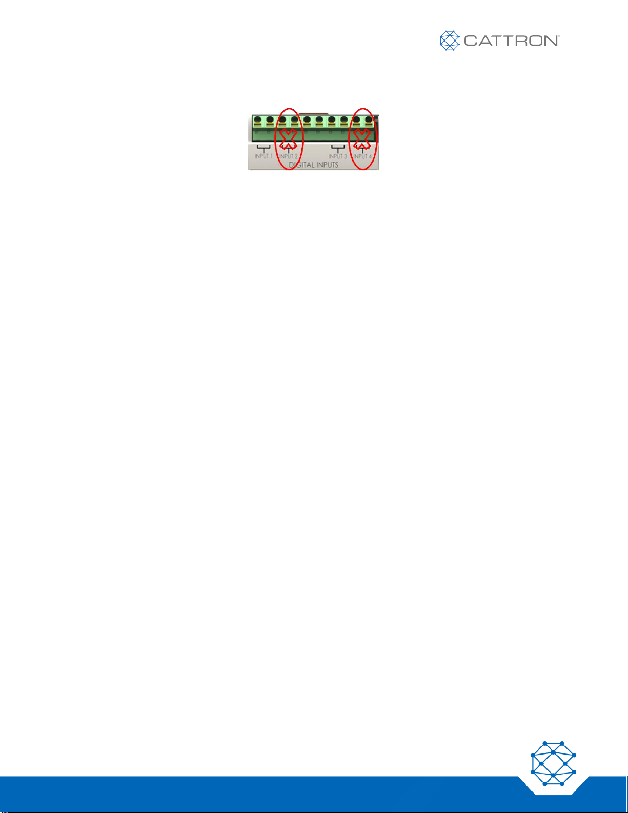
84
Version 17
Safe-E-Stop™
User Guide
The input contacts INPUT 2 and INPUT 4 have no assigned function and should not be connected. They are
reserved for future use.
THIS MANUAL CONTAINS MANY IMPORTANT WARNINGS AND CAUTIONS THAT SHOULD BE REVIEWED PRIOR TO
INSTALLATION, COMMISSIONING, CONFIGURATION CHANGES, OR DECOMMISSIONING. THESE WARNINGS CAN
BE FOUND IN CHAPTER 2.
Page 85
85
Version 17
Safe-E-Stop™
User Guide
Appendix I: Safety Performance Level
The Safety performance level provided below was calculated with IEC 61508 and the equivalent ISO13849
performance level is shown in brackets.
FUNCTION TYPE
FUNCTION
SAFETY PERFORMANCE LEVEL IEC
61508
PROBABILITY OF FAILURE PER
HOUR ( PFH )
COMM LOSS
Automatic Safety Function
COMMUNICATION
LOSS
SIL3 (ISO13849 PLe)
PFH = 1.58248e-09
ESTOP
After manual activation
ESTOP
SIL3 (ISO13849 PLe)
PFH = 1.90565e-09
For detailed information on the failure modes, failure rates and safe failure fraction, please contact Cattron
division and ask for “parameter for failure rate determination.”
Due to continuous product improvement, the information provided in this document is subject to change without notice.
Cattron Support
For remote and communication control systems support, parts and repair, or technical support, visit us online at:
www.cattron.com/Contact
Safe-E-Stop™ is manufactured at the following location:
Cattron North America Inc., 655 N River Rd NW, Suite A, Warren, OH 44483
9M02-8978-A001-EN
Version 17
 Loading...