


MANUALE ISTRUZIONI
OPERATOR’S HANDBOOK
MANUEL D’UTILISATION
GEBRAUCHSANWEISUNG
MANUAL DE ISTRUCCIONES
TURBO
A UNIVERSAL ASPIRATOR

ITALIANO
Dati generali di funzionamento 50/60 Hz .........................................................................2
Introduzione ......................................................................................................................3
Segnali ed avvisi ...............................................................................................................3
Montaggio e messa in funzione ........................................................................................4
Manutenzione ordinaria ....................................................................................................8
Manutenzione straordinaria ..............................................................................................9
Istruzioni per muoversi e modi care alcuni parametri nei menù di Turbo-Smart ............10
Istruzioni per settare la comunicazione Zig-bee (wireless) .............................................17
Descrizione allarmi .........................................................................................................22
Avvisi importanti .............................................................................................................23
Trasporto e stoccaggio ...................................................................................................23
Trasporto di apparecchi usati ..........................................................................................23
Illustrazioni......................................................................................................................121
INDICE
TURBO
A UNIVERSAL ASPIRATOR
1
2
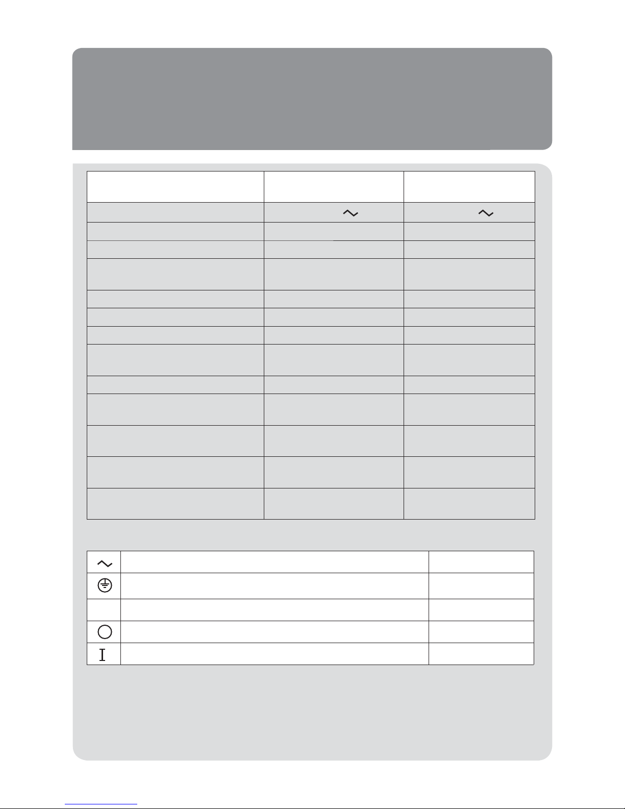
• Dati generali di funzionamento 50/60 Hz
Aspiratore ad uso dentistico Turbo-Smart
Modello Turbo-Smart “A” Turbo-Smart “B”
Tensione nominale 230 V 230 V
Frequenza nominale 50/60 Hz 50/60 Hz
Corrente nominale 7 A 9 A
Modalità di impiego Funzionamento
continuo
Funzionamento
continuo
Protezione contro l’umidità Comune Comune
Potenza massima assorbita 1,45 kW 1,87 kW
Portata massima 86 m³/h 105 m³/h
Prevalenza massima per il
servizio continuo
2000 mm H2O 2000 mm H2O
Velocità di rotazione 70 hz 85 hz 70 hz 110 hz
Pressione sonora versione
scarenata
68,4 dB(A) 69 dB(A) 68,4 dB(A) 73,7 dB(A)
Pressione sonora versione
carenata in plastica
66,4 dB(A) 67 dB(A) 66,4 dB(A) 72 dB(A)
Pressione sonora versione
carenata per interno
48,5 dB(A) 49,5 dB(A) 48,5 dB(A) 52,2 dB(A)
Pressione sonora versione
carenata per esterno
54 dB(A) 55 dB(A) 54 dB(A) 58,7 dB(A)
Corrente alternata IEC 417-5032
Terra di protezione IEC 417-5019
Grado di protezione contro i contatti diretti o indiretti IEC 60204-1
Aperto (sconnessione dalla rete di alimentazione) IEC 417-5008
Chiuso (connessione alla rete di alimentazione) IEC 417-5007
Livello di pressione sonora rilevato secondo la norma ISO 3746-1979 (E).
Parametri: r = 1,5 - rumore di fondo: 34 dB(A) - strumento Bruel & Kjaer type 2232.
ENGLISH
General 50/60 Hz running data.......................................................................................26
Introduction ....................................................................................................................27
Signals and warnings .....................................................................................................27
Installation and starting ..................................................................................................28
Routine maintenance .....................................................................................................32
Extraordinary maintenance ............................................................................................33
Instructions to navigate Turbo-Smart menus and to modify some parameters ............34
Instructions for communication settings Zigbee (wireless) ............................................41
Alarms description .........................................................................................................46
Important notices ...........................................................................................................47
Transport and storage ....................................................................................................47
Transport of second-hand appliances ............................................................................47
Pictures ........................................................................................................................121
25
INDEX
TURBO
A UNIVERSAL ASPIRATOR

26
• General 50/60 Hz running data
Turbo-Smart dental aspirator
Model Turbo-Smart “A” Turbo-Smart “B”
Rated voltage 230 V 230 V
Rated frequency 50/60 Hz 50/60 Hz
Rated current 7 A 9 A
Operating conditions Continuous
operation
Continuous
operation
Protection against
ingress of liquids
Ordinary Ordinary
Max. absorbed power 1,45 kW 1,87 kW
Max. fl ow 86 m³/h 105 m³/h
Max. head for
continuous service
2000 mm H2O 2000 mm H2O
Rotation speed 70 Hz 85 Hz 70 Hz 110 Hz
Sound pressure
version without box
68.4 dB(A) 69 dB(A) 68.4 dB(A) 73.7 dB(A)
Sound pressure
version with plastic box
66.4 dB(A) 67 dB(A) 66.4 dB(A) 72 dB(A)
Sound pressure level version with
box for indoor installation
48.5dB(A)49.5dB(A) 48.5 dB(A) 52.2 dB(A)
Sound pressure level version with
box for outdoor installation
54 dB(A) 55 dB(A) 54 dB(A) 58.7 dB(A)
Alternating current IEC 417-5032
Earthing IEC 417-5019
Degree of protection against electric shock IEC 60204-1
Open (disconnected from the main electrical supply) IEC 417-5008
Closed (connected to the main electrical supply) IEC 417-5007
Sound pressure level tested according to the standard ISO 3746-1979 (E).
Parameters: r = 1,5 – background noise: 34 dB (A) – instrument Bruel & Kjær type 2232
ENGLISH
27
This booklet is intended to illustrate the installation and starting of the appliance.
It also informs of possible dangers and about the precautions to be taken for accident prevention.
This manual should be always available for consultation during unpacking, use, installation and
starting of Turbo-Smart.
Our updated manuals are available on the web site www.cattani.it. We recommend their consul-
tation especially for updates about safety.
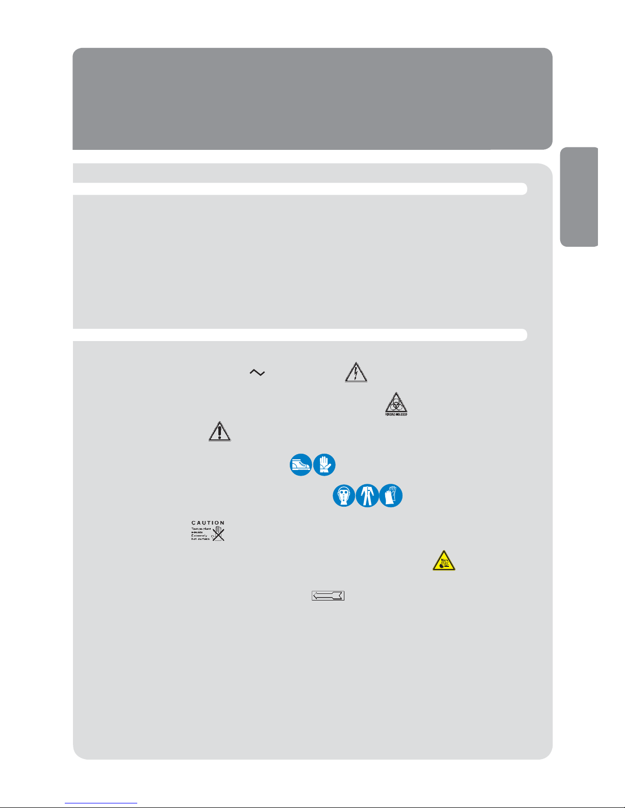
• Introduction
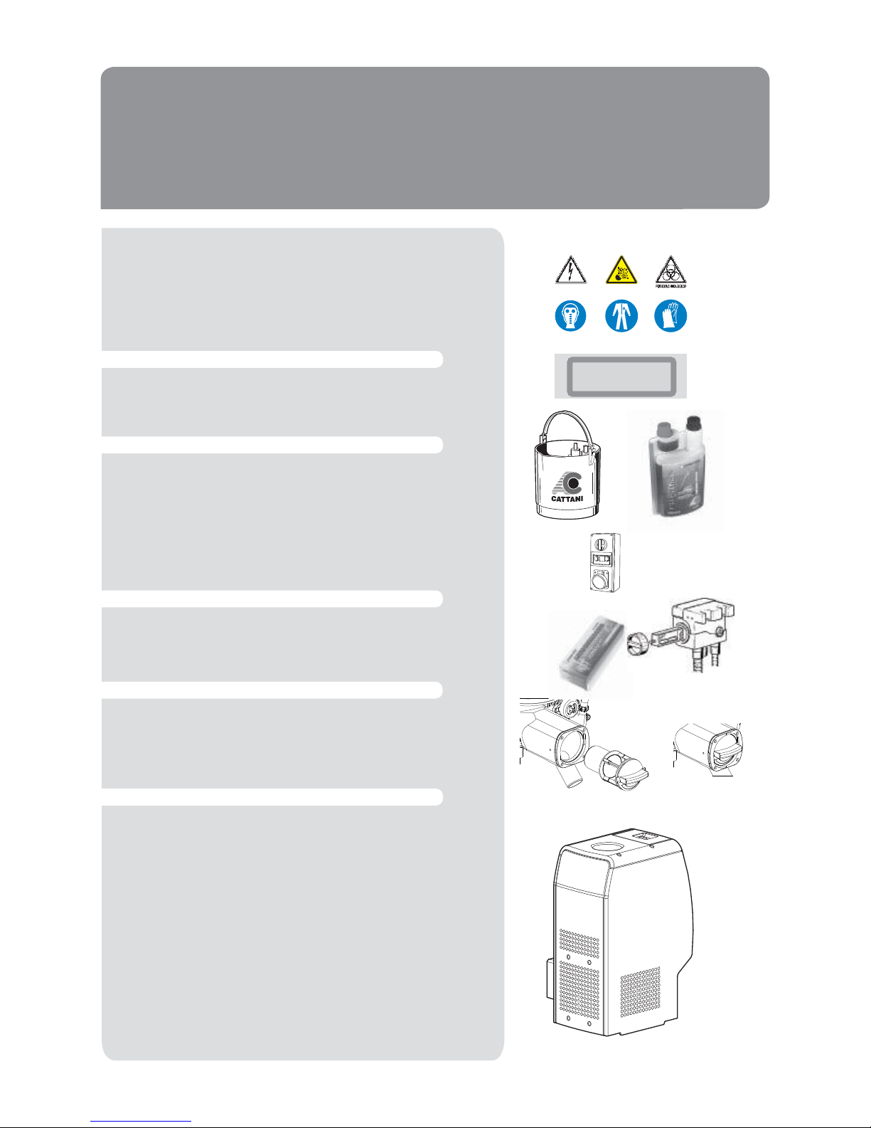
• Electrical shock risk: also 230 V can be lethal.
• Biological danger, risk of infections from epidemic diseases.
• General danger sign.
• Personal protections for heavy works.
• Personal protections against biological danger.
• High temperature.
• Keep the room free from fl ammable, corrosive or explosive material.
• Compulsory direction of fl ow or of rotation.
• Signals and warnings
Warning signs cannot always fully express danger warnings, therefore it is necessary that
the user reads the warnings and keeps them in due consideration.
Failure to observe a danger sign or warning may harm operators or patients.
Safety devices must not be removed. Appliances or their functioning must never be modifi ed.
Despite all our efforts, it is still possible that danger warnings are not exhaustive: we apologise to
the users and kindly request them to care for all danger sources that might have passed unnoticed and to inform us accordingly.
• Introduction
• Signals and warnings
28
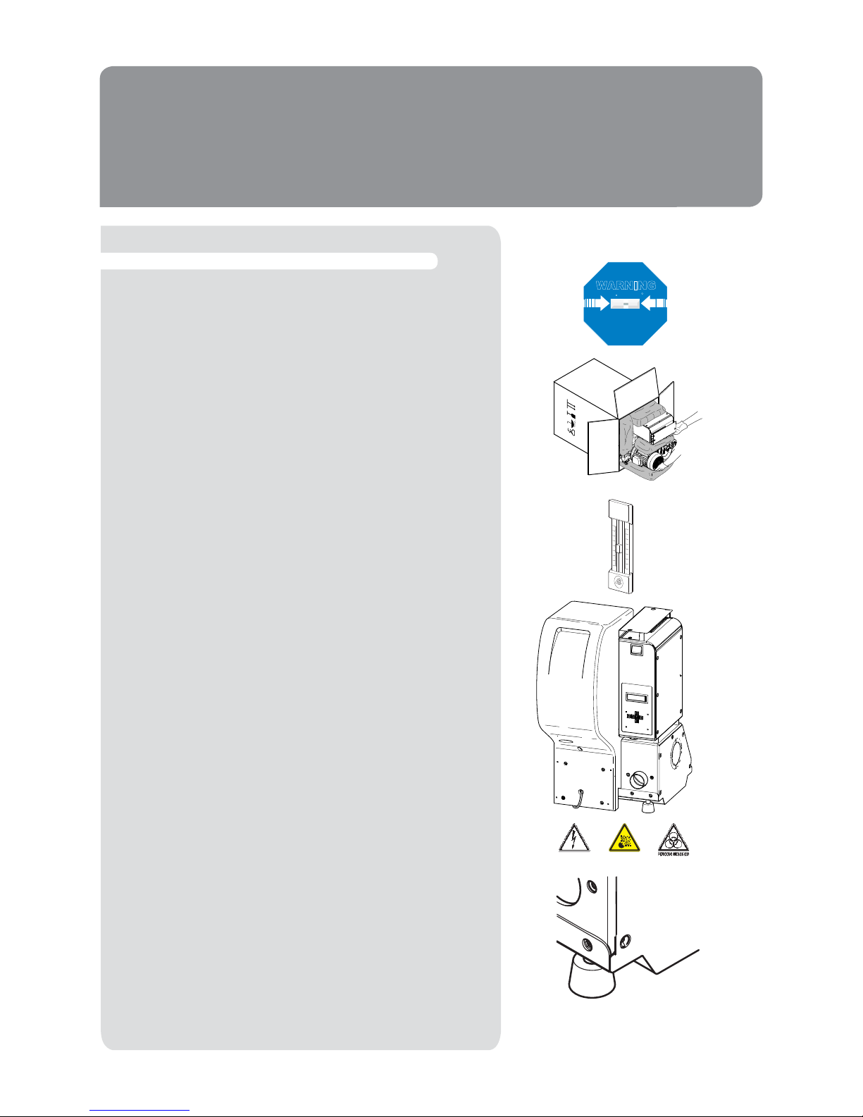
• Installation and starting
• Recommended precautions
Before unpacking the appliance, check the warning shockwatch on the carton. In case of it being red or the carton
being damaged, accept the material reserving the right to
examine the machine.
Unpack the appliance following the instructions shown on
the package. The carton is recyclable. Dispose of it in compliance with regulations in force.
The machine installation must be carried out by a specialist
equipped with the necessary tools. Install the appliance in
a clean location, far from heat sources, humidity and dust.
Turbo-Smart can be installed outdoors (on a balcony, in veranda or gardens), provided that it is sheltered from rain,
splashing, humidity, frost and direct sunshine.
For outdoor installation we recommend the use of our
special designed box tted with double isolating roof, antifreeze and ventilation systems (both tted with xed thermostat for automatic temperature control).
In the plant room temperature can range from a minimum of
+ 5 °C to +35 °C max.
Turbo-Smart tted with box, for indoors our outdoors installation, can be supplied with antifreeze device. In case
the plant room must be ventilated or air-conditioned, we
suggest to contact a thermo-technician for a personalized
project. The plant room must be closed to patients and extraneous people. If such a room is not available, machines
must be protected by a suitable cover, which must not be
easy to remove. Use protections and danger warning boards to prevent accidental risk from electrical shocks or the
possibility (unlikely but not excludible) of re, explosion and
contaminating air or liquid leakage. Use indoors and outdoors boxes designed and produced by the manufacturer of
the machines only.
Keep the plant room free from ammable material. Make
sure that there is no possibility for gas leakages. Do not
connect damaged appliances to the mains. Do not use extension leads, multiple plugs or sockets. Before connecting the machine to the mains, ascertain that the feeding
line is complying with the regulations C.E.I. 64-8 and that
a thermal switch and a residual current operated circuitbreaker (class A or B) (16A) according to the regulations
EN 61008-1 are present. Light coloured, wooden, linoleum,
rubber or marble oors can change colour or get marked if
they are kept in contact with rubber vibration-proof devices
(1). Therefore, it is necessary to use a rubber sheet or some
other suitable material to isolate vibration-proof devices
from the oor.
HANDLE
WITH CARE
WARNING
WARNING
SHOCKWATCH
R
RED INDICATES ROUGH HANDLING
IF RED, NOTE ON BILL OF LADING
INSPECTION MAY BE WARRANTED
MODEL L-55 (37g)
TOLL FREE 1-800-527-9497
www.shockwatch.com
M
inim
a
M
a
x
im
a
3
0
2
0
1
0
0
1
0
2
0
3
0
4
0
5
0
5
0
4
0
3
0
2
0
1
0
0
1
0
2
0
3
0
1
ENGLISH
4
29
• Installation
Before connecting the aspirator to the piping of the centralized system, ascertain that aspiration piping is clean as
heavy debris could damage the appliances.
Connect the PVC light grey aspiration tube (2b) (supplied
with the machine) to the 50 mm Ø tube-holder (2) (“aspirated
uid inlet”).
The other end of the same tube must be connected to the
aspiration piping (3) coming from the surgeries (page 30).
The black heat resistant exhaust air pipe (4b), tted with a
metal spiral, must be connected to the 50 mm Ø tube-holder
(4) (“exhaust air outlet”).
Connect the other end of the pipe to the antibacterial lter
(5), passing preferably through a silencer (5a) supplied with
the aspirator. The hot air coming from the antibacterial lter
must be conveyed outside.
Connect the 18 mm Ø tube-holder (6) to the liquid drain pipe.
In the version tted with Hydrocyclone the aspirator is draining liquids by gravity, therefore these can never be drained
towards the top. The 10 mm Ø tube-holder (8) (“emergency
drain”) must be connected to the liquid drain pipe.
The piping connecting the machine to the aspiration and
draining system should be exible to damper the small
vibrations produced by the aspirator.
The aspiration piping should be run in the oor and at a point
near the aspirator it should rise about 30 cm to reach the
tube-holder (2) ( g. A and B, page 121).
If Turbo-Smart is installed on a lower
oor than the dental units, the aspiration
piping must not enter the centrifugal
separator perpendicularly.
Rather, place a few metres of piping
horizontally on the same level of the
machine and then install it at the centrifugal separator inlet which is on a higher
level (use a exible pipe) ( g.B, page
121). The aspirated uid is reaspirated
by Turbo-Smart.
After the installation, connect the power
cable to the mains according to the
regulation EN 61008-1.
Finally connect the low voltage users line:
the clamps 19 and 20 of the circuit AC8007 ( g. C “AC80-07 wiring diagram”,
page 122) to the users line (12) (det.12,
page 30 and g. F, page 125) which is
feeding all the dental units of the same
system with connections in parallel.
Ascertain that the contact on the dental
unit is clean (free contact without voltage).
6
3
2
4b
8
4
2b
5
5a
20
2
6
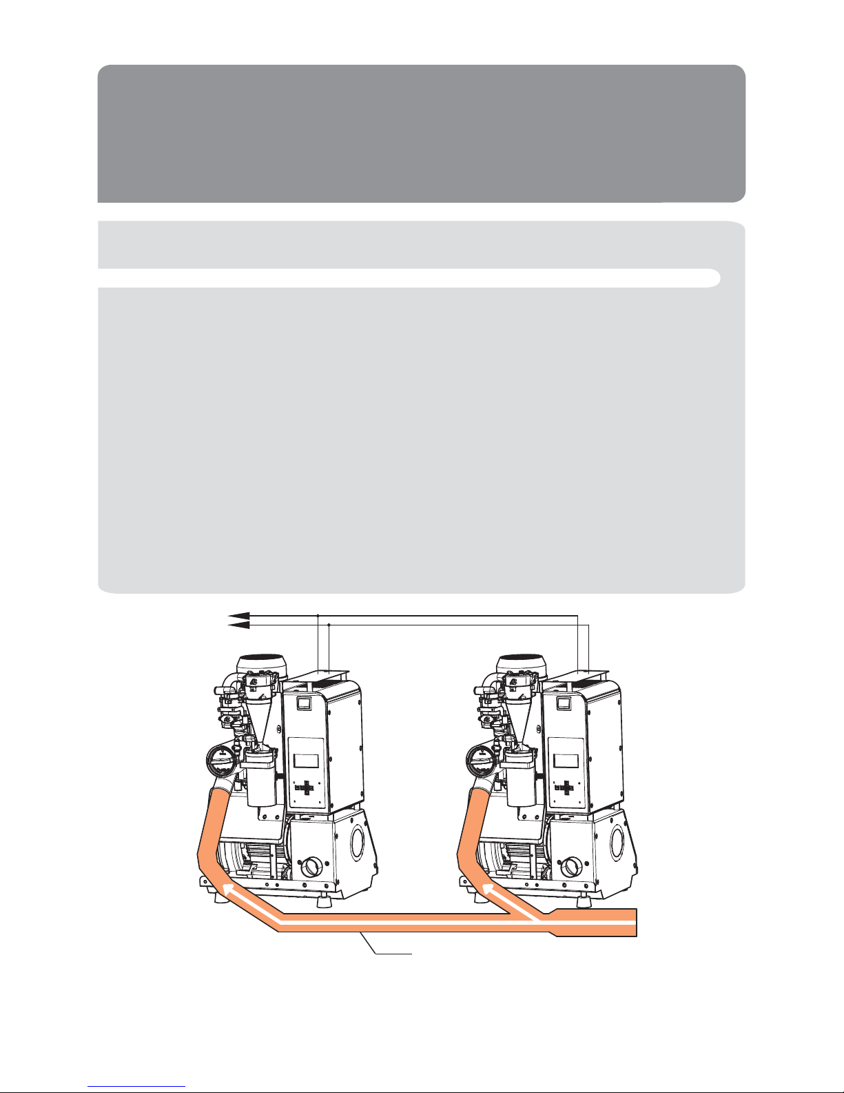
It is advisable to install in parallel only machines with the same ow and head values. With the installation of 2 or 3 Turbo-Smart units in parallel ( g. F) the total ow is doubled or tripled, provided that
the diameter of the main piping is increased of 10 mm for each additional aspirator unit. In the same
way the diameter of the exhaust air pipe must be increased. Turbo-Smart is supplied complete with
all the accessories which are necessary for the installation in parallel, therefore no one-way valves,
supplementary control panels or peripheral units are needed. After connecting 2 or 3 Turbo-Smart
units in parallel to the same main piping, connect in parallel the users wires (12) coming from the
different dental units. Installing Turbo-Smart units in parallel, pay attention not to invert the small
cables of the connection no.19 with the small cables of the connection no.20 ( g. C, page 122). With
multiple aspirators in parallel it can occur that one unit stops and that the operators do not notice it.
In order to bring this to the clinic staff’s attention, the connections 8 and 9 of the control panel (clean
contact) ( g. C, page 122) allow a remote alarm signal to be connected in a room under frequent
control. More Turbo-Smart units in parallel can offer better performance and allow the clinic to save
energy when they are working simultaneously, independent of the suction demand. Disconnecting
one or more aspirators doesn’t result in a saving of energy and also decreases the suction power
of the other machines.
3
12
30
• Installation in parallel
Fig. F
Draw. F
ENGLISH
31
Install and connect the aspirator, select the position ON on
the switch, which will light up after one of the dental units
has started working. At this point aspiration will start.To
check if Turbo-Smart is working correctly, it is advisable to
carry out the dynamic tests (see g. D, page 123 and the
Turbo-Smart working diagram g. E, page 124). Users must
be instructed on the aspirator use and routine maintenance
of new, not used, and therefore not yet contaminated, machines. Show users how to follow the Turbo-Smart working
phases on the display, to interpret danger warnings and
to carry out routine maintenance using Puli-Jet plus new
(A) - (by means of Pulse-Cleaner) (B) - and Antifoaming
Tablets (C).
The aspirating unit (9) (through pipe 10) creates vacuum
inside the centrifugal separator (11). The uid coming from
the dental units enters the centrifugal separator (11) from
the collecting pipe (2). The centrifugal separator separates
air from liquids: air is exhausted outside through the pipe
(4) whereas liquids (in the version without amalgam separator) are drained to the sewage through the waste pipe
connected to the tube-holder (6). The centrifugal separator
(11) is starting before the aspirating unit (9), this allows to
drain the liquids which might collect inside the centrifugal
separator before aspiration starts. Moreover, when the machine is switched off a timer (adjustable) is keeping the motor running for min.10’’ - max. 120’’.
On request, Turbo-Smart can be supplied with the amalgam
separator “Hydrocyclone ISO 18” having its separate manual.
Starting, fi nal test and users instruction
Working
Amalgam Separator ISO 18
BA
C
11
9
10
2
6
4
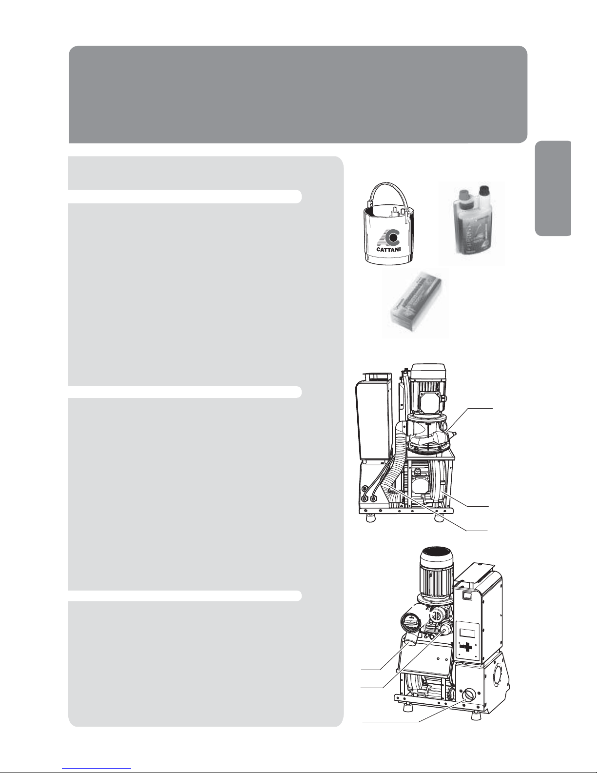
• Routine maintenance
Routine maintenance must be entrusted to specially instructed surgery staff.
• We recommend to pay special attention to all danger signals and to use goggles, gloves and disposable overalls
for personal protection.
• Check for any possible alarm on the display. In case of
alarms, contact the technician.
• At the end of every working day aspirate a solution of Puli-Jet plus new disinfectant with anti-scale agent (A) using
Pulse Cleaner (B);
• Disconnect the machine from the mains before any intervention.
• Place the Antifoam Tablets on the dental unit lters.
• Keep the aspirator lter clean.
• Make sure that the aspirator ventilation is not obstructed;
• Keep the plant room free from anything not related to the
machines, especially from ammable material. Make sure
that there is no possibility for the formation of corrosive,
ammable and explosive mixtures.
Daily
Occasionally
BA
Every evening
Daily
Periodically
32
ALLARME:
TEMPERATURA ELEVATA
 Loading...