

Page 1
Assembly Instructions
Model 64026
The Deep Storage WorkCenter with Contoured Top
A. This unit is Ready-to-Assemble. Catskill uses positive fastening methods such as wood screws and in
some places hidden Bastion fasteners. You will need some standard household tools: hammer and screwdriver. A power screwdriver is recommended for some applications. Where possible, we have packaged
some of the screws in separate labeled packages. Note label for screws and when they are to be used in
assembly in the instructions.
B. Directions (left/right, front/back) are given as facing the front of an assembled upright unit.
C. A friend is recommended to assist with assembly as this will ease the process. Some of the parts are
large and awkward to hold in place, an extra pair of hands will help.
D. See video assembly tips on www.catskillcraftsmen.com
Page 2
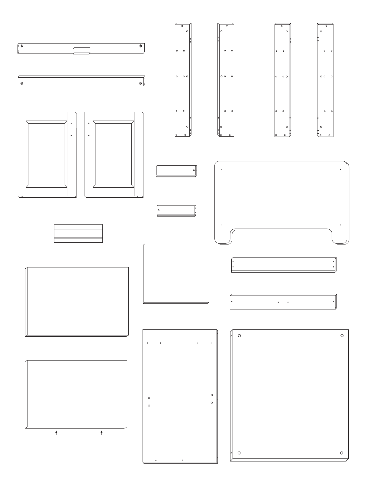
PARTS 64026
P/N: B-27/2/64026/TF
Top Front Brace (1)
Inside View
P/N: B-27/2/64026/BF
Bottom Front Brace (1)
Inside
Inside View
Inside View
P/N: DOOR-64026R
Right Door (1)
P/N: SIDE SHELF-64026
Side Shelf (8)
INSIDE
P/N: DOOR-64026L
Left Door (1)
P/N: L-31/5/RF/64026 P/N: L-31/5/LF/64026
Front Legs (2)
P/N: DS-18R 64026
Right
Drawer Side (1)
P/N: DS-18L 64026
Left
Drawer Side (1)
P/N: DBOT 64026
Drawer Bottom (1)
P/N: L-31/5/LB/64026 P/N: L-31/5/RB/64026
Back Legs (2)
P/N: TT 64026
Table Top (1)
P/N: DBK 64026
Drawer Back (1)
P/N: DF 64026
Drawer Front (1)
P/N: 64026/BOT
Bottom Shelf (1)
EDGE BANDING
P/N: 64026/MID
Middle Shelf (1)
Outside View
P/N: SP 64026
Side Panel (2)
Inside View
P/N: BP 64026
Back Panel (1)
Page 3
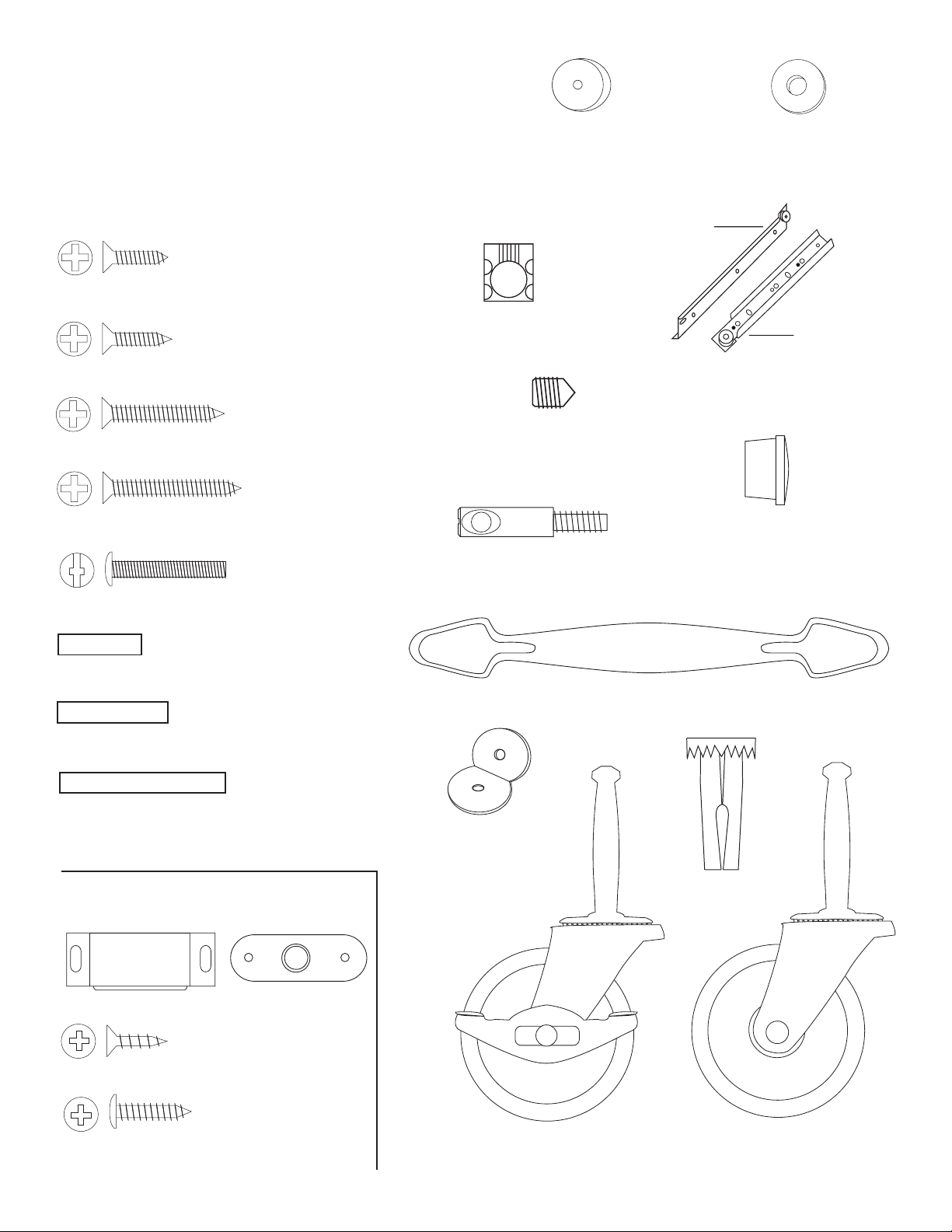
Hardware 64026
IMPORTANT NOTE ON SCREWS: Separate screws
into piles with a note on use as some are very similar.
DO NOT use the larger diameter 5/8” #8 screws to
attach the drawer glides. Screws for the glides have
flat heads & are much smaller in diameter. Double Check!!
(used drawer glides)
5/8” Phillips Flat Head #5 Screw (4)
(used to attach
butterfly bracket)
5/8” Phillips Flat Head #8 Screw (8)
1” Phillips Flat Head #6 Screw (4)
(used to attach cabinet
drawer glides)
P/N: SPACER
Plastic Spacer (4)
(Goes between cabinet
drawer glide & side panel)
P/N: B-NUT
Bastion Barrel Nut (10)
P/N: SET SCREW
Bastion Set Screw (10)
3/16” Flat Washer (2)
Drawer
Cabinet
Drawer Glide (1 Set )
1 1/4” Phillips Flat Head #8 Screw (16)
(used on door/
drawer handles)
1” Truss Head Machine Screw (6)
(Brace pins)
3/4” Long 3/16” DIA. Steel Pin (4)
(Shelf pins)
1” Long 3/16” DIA. Steel Pin (40)
(Door pins)
1 1/2” Long 3/16” DIA. Steel Pin (4)
Magnet Pack
5/8” Wooden Disk (12)
(Packed with Hardware)
P/N: B-POST
Bastion Post (10)
P/N: HANDLE 64024
Nickel Handle (3)
Butterfly
Brackets (4)
Caster Socket (4)
Magnet (2)
Magnet Plate (2)
(Used on Magnet Plate)
1/2” Phillips Flat Head #4 Screw (2)
(Used on Magnet)
5/8” Pan Head Screw (4)
P/N: WHEEL 2L (LOCKING)
Locking Wheel Casters (2)
P/N: WHEEL 2 (NON-LOCKING)
Wheel Casters (2)
Page 4
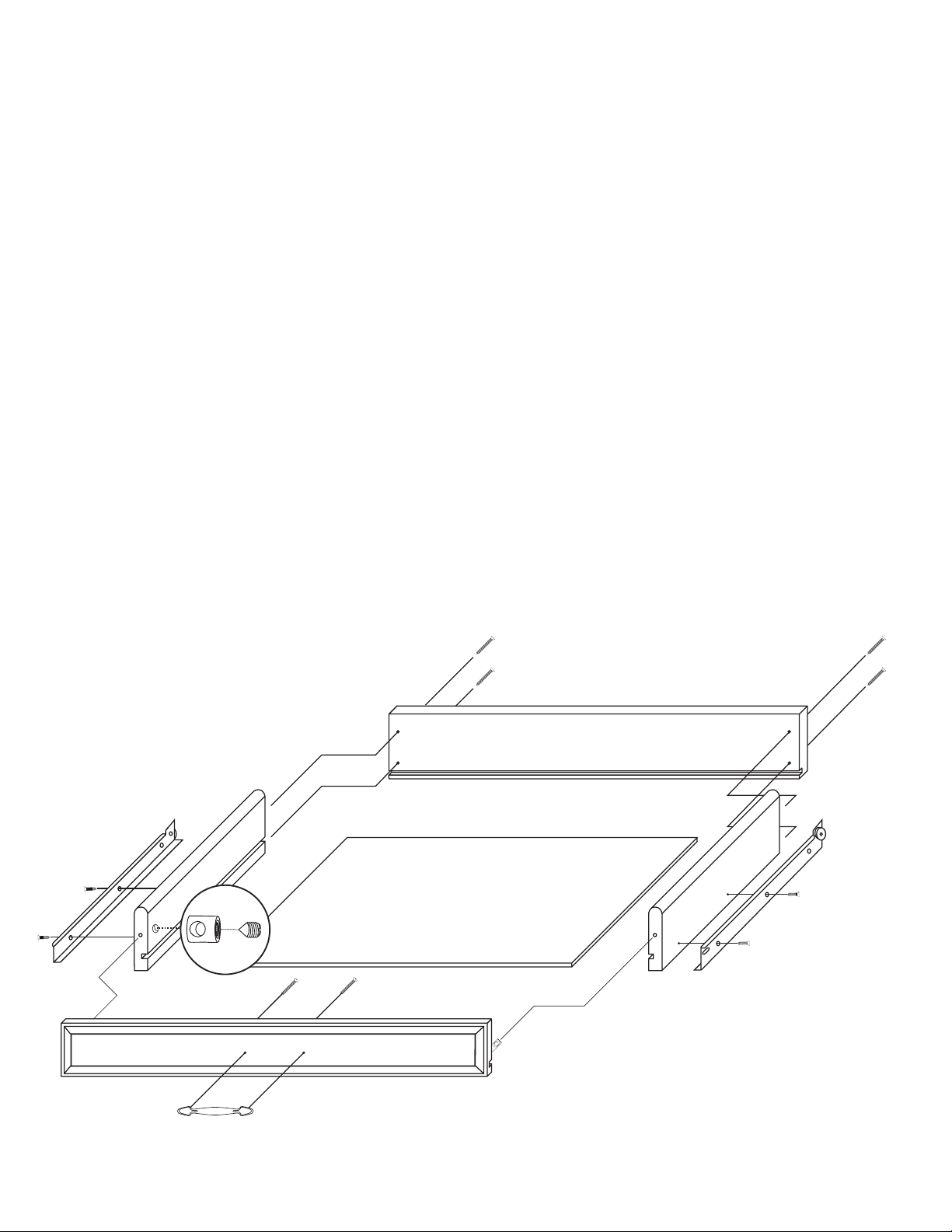
STEP 1
Assemble Drawer
A. Attach the drawer back to the drawer sides with four 1 1/4” #8 screws. There are left and right sides.
Make sure the slots that run the length of the sides are aligned with the slot in the drawer back to accept
the drawer bottom.
B. Slide in drawer bottom, best side up to inside of drawer.
C. Take 2 bastion posts, align the threaded end of the posts with the post holes located near the ends
of the inside of the drawer front. Tighten posts down until the solid shaft of the post hits the wood. Back
post out about 1/2 turn until the hole/screwdriver slot in the end of the post is parallel and in direct line
with the long edges of the Drawer Front.
D. Insert the barrel nuts into the nut access holes on the inside of the drawer side with the threaded
end of the nut facing out. Take the drawer front and carefully insert the posts into the ends of the brace
sides, through the sides of the nut until seated. Push nut snug up against the wood in the nut access
hole toward the inside drawer front. Hole should be slightly off-center toward the drawer front. Insert the
set screw and tighten down with a Phillips screwdriver. See illustration. The ends of the sides should be
tight against the inside drawer front.
E. Attach the drawer handle with the 1” Truss Head Machine Screws.
F. Attach the drawer glides (left and right) to the Drawer Sides using two 5/8” #5 screws per side.
Wheels go toward drawer back and are up.
Illustration 1
Page 5
STEP 2
INSIDE VIEW
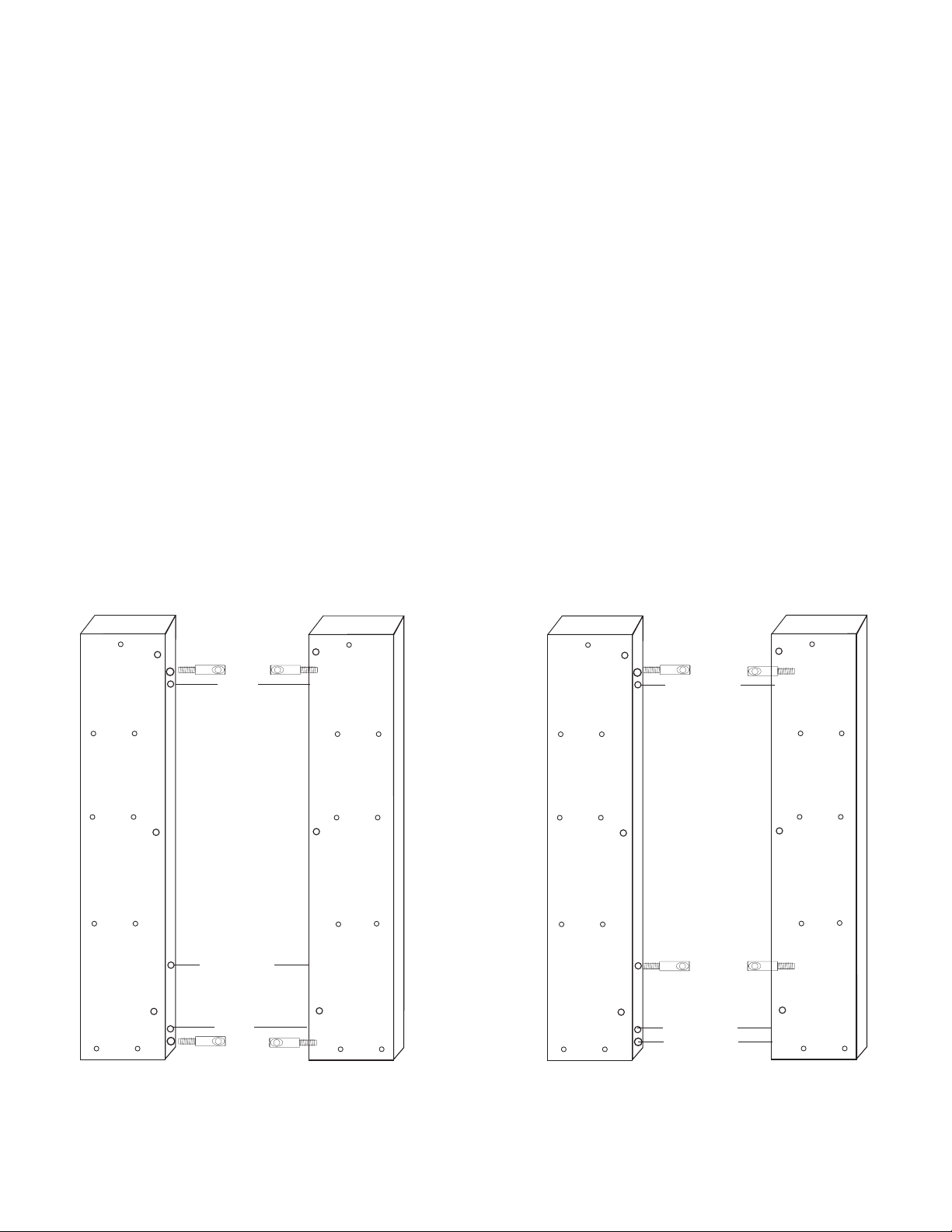
Attach Posts To Legs
A. There are 2 right legs and 2 left legs. Diagonal legs are the same (Example: Right Front /Left
Back). See Illustration 2 below which shows the legs paired (inside view) for the front and back panels
respectively. Notice that the position of the posts in the front legs differ from those in the back legs. This
difference will mean that there are some holes that are not used on all legs.
B. Take all 4 legs and lay out in pairs as in Illustration 2. Each pair of legs should be mirror images of
each other! Make sure the bottoms of the legs (hole in each of legs for caster is bottom) are down as
they are in the illustration.
C. On the Front Legs, posts will go into holes #1 and #5 counting down from the top. On the Back Legs,
posts will go into holes #1 and #3. On the Front Legs, hole #3 is not used. On the Back Legs, holes #4
and #5 are not used.
D. To seat posts, tap the slotted end of posts with hammer until threads just enter holes; then tighten
down (see “Tips On How The Bastion System Works” for alternative methods) until the solid shaft of the
post hits the wood, then back about 1/2 turn so that the hole in the post is perpendicular to the length
of leg/wood grain. Screw posts into all 4 legs. Double check with Illustration 2.
(B)
(B)
(B)
(B)
(A)
(A)
(A)
FRONT LEGS
TOP
Posts
Pins
NOT USED
Pins
Posts
(A)
(B)
(B)
(A)
(B)
(A)
(B)
(A) Thru holes
used to attach
Side Panels
(B) Pin holes
for pins that
support Side
Shelves Sets
of 2
(B)
(B)
(B)
(B)
(A)
(A)
(A)
BACK LEGS
TOP
Posts
NOT USED
Posts
NOT USED
NOT USED
(A)
(B)
(B)
(A)
(B)
(A)
(B)
RIGHT
LEFT
Illustration 2
LEFT
RIGHT
Note: Only the post holes are used
on Back Legs Step 1.
Page 6

STEP 3
Nut Access Holes
Nut Access Holes
Illustration 2
Assemble Cabinet Back
A. Take the Back Panel and the Back Legs, lay out as in illustration 3. The Back Panel cannot be installed
improperly since the top and bottom hole measurements are the same distance top to bottom.
B. Drop a Barrel Nut, open
end up, into each of the
large nut access holes in
the Back Panel. There are
small indented marks on
the lip of the open end of
the Barrel Nut. This shows
the alignment of the holes
through the sides of the
Back Panel. Continue
seating Post until Post goes
thru the sides of the Barrel
Nut and the hole in the post
can be seen through the
threaded end of the nut.
When the back panel is ush
against the inside of the leg,
the hole in the post should
be offset toward the side of
the access hole adjacent
to the post. Insert the Set
Screw and tighten down
with Phillips screwdriver. Set
Screws should thread easily.
DO NOT CROSS THREAD
OR FORCE. As you tighten
the Set Screw down, the
tip of the screw will seek
the center of the hole in the
post, thereby pulling the side
of the Barrel Nut against the
inside edge of the access
hole and toward the leg. If
the nut is loose and does
not tighten down against the
wood after the Set Screw
is tightened then you will
need to remove the leg(s)
and tighten the Bastion Post
down another 1/2 turn, then
repeat above.
Nut Access Holes
Nut Access Holes
Illustration 3
Inside View
C. Attach Right Leg to Back
Panel in the same manner.
Illustration 3A shows the
assembled Back Panel.
Illustration 3A
Page 7

STEP 4
Assemble Cabinet Front
A. Take the 2 Front Braces (Illustration 4) and tap/insert one 3/4” pin into each end of each brace. Take
the 2 doors and tap/insert one 1 1/2” pin into each end of each door. With pins in place lay out Braces,
Doors and Front Legs as illustrated in Illustration 4A.
B. Place 1 washer on each bottom door pin. Push door pins into the Bottom and Top Front Braces until
seated. Next, attach this door assembly to the Left Back Leg with Bastions. Then attach the Right Back
Leg in the same manner (as shown in Step 2). Illustration 4B shows an assembled cabinet front.
Top Front Brace
Post Hole
Pin Hole
Magnet Block
Door Pin Holes
(Inside View)
Bottom Front Brace
Illustration 4
Door Pin Holes
Pin Hole
Post Hole
Washer
This Hole is Not Used
Washer
Illustration 4A
Page 8

Washer
Illustration 3A
This Hole is Not Used
Illustration 4B
C. Invert the Front Cabinet Assembly. Attach the magnet plate to the inside top of the left door using
a at head 1/2” #4 screw. Stick the magnet to the magnet plate on the Right Door. With the Left Door
open, close the Right Door. The Magnet should be positioned over the wooden block on the bottom of
the Top Front Brace. Hold the magnet in place with your thumb and open the Right Door. The Magnet
will be in he correct position on the block. Secure the Magnet with the two Round Head Screws in the
magnet packet. Center screws in the slot in the magnet. This will allow adjustment later, if needed.
Repeat with the Right Door.
Illustration 4C
Page 9

STEP 5
Attach Front Assembly to Back Assembly with Side Panels
A. This step is easier with 2 persons! Take the front assembly and attach the 2 side panels with three
1 1/4” screws per side. Push screws through the three holes on the front face of each leg, aligning
the screws with the pilot holes in the long edges of the panels. Start all three into the pilot holes, then
tighten them down. Repeat with the other side panel. Illustration 5 shows side panels in place attached
to the front assembly.
Illustration 5
Page 10

B. Take the back
Attach back panel with 1 1/4”
Phillips Flat Head #8 Screws
assembly and attach
it to the side panels
using three 1 1/4”
#8 screws as above.
Illustration 5A shows
back panel assembly
going into place.
Illustration 5B shows
cabinet assembly at
this point.
Illustration 5A
Illustration 5B
Page 11

C. Attach the drawer glides to the side panels using 1” #6 screws and round plastic spacers. See
Illustration 5C to locate holes. See Illustration 5C for glide attachment guide. Make sure you have the
right screw (this is the small diameter screw).
Note: Although there are 4 holes in our side panels for glide screws, use holes 1 and 3 front to back.
Insert Round Plastic Spacer
Glide holes
Not Used
between cabinet and drawer glide
Front Brace omitted to show placement
Not Used
Plastic Spacer
Plastic Spacer
Glide
Illustration 5C
Note: Drawer glides are ush with front edges of side panels. Use holes in glides that align with
1st and 3rd pilot holes in the side panels as glides may have more or less holes than illustrated.
Page 12

STEP 6
Final Cabinet Assembly
A. Invert top onto a smooth at surface. On Model 64024 there is no difference between the front and
back of the Top, On Model 64026 make sure the projected wings are toward the front. Attach two of the
buttery brackets to each leg with 5/8” #8 Screws. See Illustration 6.
Attach 2 Butterfly Brackets
on each Leg as illustrated
using 5/8” #8 Screws
Illustration 6
Page 13

B. With unit still upside down, tap the 4 caster sockets into the holes in the bottoms of the legs. Tap in
the 4 casters by hitting straight down on the solid part of the caster between the wheels.
NOTE: put the 2 locking casters in the front,
and the non-locking casters in the back.
Illustration 6A
Page 14

C. Upright the unit and tap eight 1” 3/16 diameter steel pins into each leg. Place the side shelves on the
shelf sits on top of pins
pins. Groove sin the bottom of the shelves t over the pins.
D. Open the cabinet doors and tap two 1” pins into the bottom holes of each side panel. Decide where
you want the middle shelf (it has 2 adjustments to choose from) and tap two pins into each side panel
making sure the pins are aligned side to side. Place the bottom shelf (this shelf has no edge banding)
on the back set of pins and with front of shelf slightly elevated, close doors and the shelf will drop into
place. Take the middle shelf, edge banding out, and place the shelf on the pins. See Illustration 6B for
pin locations.
Groove in side
Underside view of side shelf.
Insert 1” pins at desired shelf height
tilt shelf to insert.
Edge banding out.
Illustration 6B
Page 15

1. The Bastion fastening system consists of a steel post (threaded on one end with a hole
TIPS ON HOW THE BASTION FASTENING SYSTEM WORKS
through the shaft on the other end); a Barrel Nut (cylindrical barrel-shaped with threaded
open end & holes through the sides); and a Set Screw (Phillips slot on one end, pointed on
the other)
2. To attach Posts: A) Dip threads of Post in vegetable oil. B) Align threaded end of Post
with hole in wood, tap on slotted end with hard hammer until threads enter, then tighten
down using a flat head screw driver or the provided allen wrench (See the Illus. Bas. 3 for
alternate seating methods). DO NOT TRY TO HAMMER THE POST ALL THE WAY IN AS IT
WILL STRIP THE POST HOLE. C) When solid shaft of Post hits wood, back out
approximately ½ turn until the hole in the posts is properly aligned as per step by step
directions. For example: the holes in the posts on the inside of the drawer front will be
parallel with the long length of the drawer front when properly seated.
3. A) Place a Barrel Nut into the nut access hole, so that the threads in the nut face out.
The small notches on either side of the nut opening, indicate the location of the holes
through the sides of the nut. B) Insert the posts through the end of the braces (or drawer
sides); through the holes in the sides of the nut. When properly aligned, you will see the hole
in the post inside the barrel nut. Post hole should be slightly off-center toward the wood.
Illustration Bas. 1
WRONG!
Post needs to be screwed deeper.
WRONG!
Post needs to be backed out.
4. Insert the Set Screw into the threaded end of the nut and tighten down. The tip of the Set
Screw will seek the center of the hole in the Post as it is tightened down, forcing the Nut
toward the main shaft of the Post. This is what tightens the wooden parts together. Set
screws should thread easily – DON’T CROSS THREAD! If Set Screw doesn’t thread easily,
check position of the hole in Post.
5. If the wooden parts are not tight against each other, the Post needs to be screwed a half
turn at a time until wood joints are tight.
Illustration Bas. 2
Step 1
Step 2
Illustration Bas. 3
Set screw secures post properly.
CORRECT!
Allen Wrench Provided
See video on our website!
If you have any questions regarding assembly or missing or damaged
parts, call our customer support number:
607-652-7321 or 888-732-7321.
Customer Support Hours are 8am-5pm Mon. - Fri. Eastern Time zone.
Page 16

For continued beauty and long life of your
Catskill Craftsmen cart, we recommend
Catskill Craftsmen’s Butcher Block Oil.
Our Butcher Block Oil is available directly from Catskill Craftsmen’s factory. For
one eight ounce (8 . oz.) bottle, which
is sufcient for two applications, simply
send $6.95 along with the completed
coupon to the address below. Visit us
online at www.catskillcraftsmen.com to
browse our assortment of butcher block
care products. Visa and Mastercard are
accepted online.
BUTCHER BLOCK OIL COUPON
Please send me______# of bottle(s) of the
Catskill Craftsmen Butcher Block Oil at $6.95
per bottle. My check or money order is
enclosed for a total of $____________.
Item code: 64026
Name _______________________________
Address _____________________________
City ________________________________
State ___________ Zip ________________
Catskill Craftsmen, Inc.
15 West End Ave.
Stamford, NY 12167-1296
Please make checks payable to Catskill Craftsmen
Inc. 15 West End Ave., Stamford, NY 12167-1296
 Loading...