

Page 1
CRAFTSMEN, INC.
Assembly Instructions
Model 1582
A. These units are Ready-To-Assemble. Catskill uses positive fastening methods such as wood
screws and in some places hidden Bastion Fasteners. You will need some standard household tools:
hammer and screwdriver. A power screwdriver is recommended . Where possible, we have packaged
some of the screws in separate labeled packages. To keep hardware separate after packets are
open, we suggest you place each type of screw into separate containers. Note labels for screws and
when they are to be used in assembly in the instructions.
B. Directions (left/right, front/back) are given as facing the front of an assembled upright unit.
C. A friend is recommended to assist with assembly as this will ease the process. Some of the parts
are large and awkward to hold in place and an extra pair of hands will help.
Model 1582
Page 2
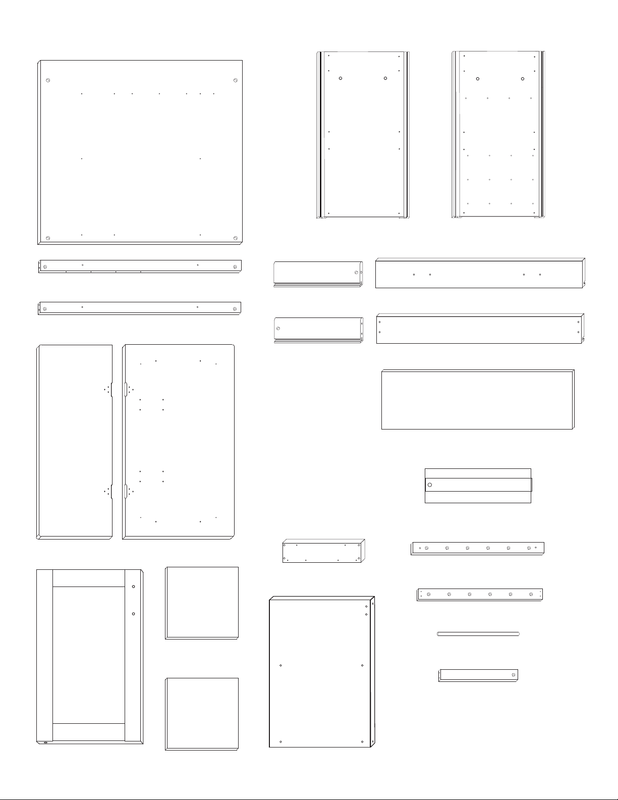
Parts List Model 1582
Back Panel (1)
P/N BP-1582
Top Front Brace (1)
P/N B34 1/4 / 2 1/2 /TOP-1582
Bottom Front Brace (1)
P/N B34 1/4 / 2 1/2 /BOT-1582
Left Side Panel (1)
P/N LFT/SP/HDL-1582
Top Right Drawer Side (1)
P/N Top DS-1582/R
Top Left Drawer Side (1)
P/N Top DS-1582/L
Right Side Panel (1)
P/N RGHT/SP/HDL-1582
Top Drawer Front (1)
P/N DF-1582
Top Drawer Back (1)
P/N DBK-1582
Top Drawer Bottom (1)
P/N TDB-1582
Stemware holder (4)
P/N STEM-1582
Drop Leaf (1)
P/N DL-1582
Door (1)
P/N Dr-1582
Table Top (1)
P/N TT-1582
Middle Shelf (1)
P/N MS-1582
Bottom Shelf (1)
P/N BS-1582
Glide Support (2)
P/N GLDSUP-1582
(left side view)
Center Divider (1)
P/N DIV-1582
Wine Rack Front Brace (3)
P/N WRFB-1582
Wine Rack Back Brace (3)
P/N WRBB-1582
Wine Rack Dowel (18)
P/N WRD-1582
Wine Rack Side Brace (6)
P/N WRSB-1582
Page 3
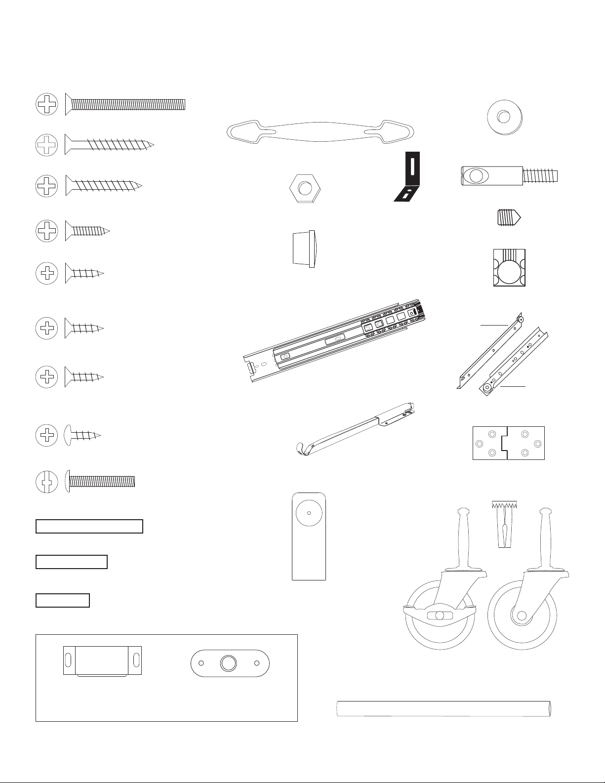
Hardware List Model 1582
To ease assembly, sort and count the hardware before getting started.
1 3/4 Phillips Flat Head Bolt (8)
Nickel Handle (3)
1 1/4 Phillips Flat Head #8 Screw (28)
1 Phillips Flat Head #8 Screw (4)
5/8 Phillips Flat Head #8 Screw (20)
5/8 Phillips Flat Head #7 Screw (4)
Bundled and labeled separately.
10-24 Hex Nut (8)
5/8 Wooden Disk (8)
3/16 Flat Washer (7)
Bastion Post (8)
L Bracket (4)
Bastion Set Screw (8)
Bastion Barrel Nut (8)
Drawer
5/8 Phillips Flat Head #6 Screw (8)
5/8 Phillips Flat Head #5 Screw (4)
Bundled and labeled separately.
3/8 Phillips Pan Head #6 Screw (30)
1 Truss Head Machine Screw (6)
1 1/2 Long 3/16 DIA. Steel Pin (2)
1 Long 3/16 DIA. Steel Pin (8)
3/4 Long 3/16 DIA. Steel Pin (12)
Full Extention
Drawer Glide (3 Sets)
P/N Drop Leaf Support (2)
Towel Bar Post (4)
Cabinet
Drawer Glide (1 Set )
Hinge (2)
Caster Socket (4)
Magnet (1)
Bundled with screws used for attaching to cart.
Magnet Plate (1)
Locking Wheel
Casters (2)
Polished Nickel Towel Bar (2)
Casters (2)
Wheel
Page 4
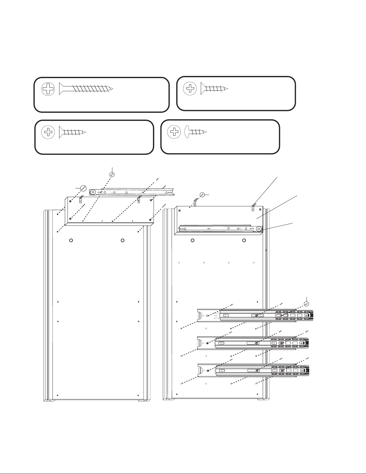
STEP 1A
IMPORTANT - There is a right and a left side panel. Lay them out as shown below in Illustration 1. Pay close attention
to the glides, that they are properly positioned when attaching to the side panels. See step 1B for specific instructions
on the full extention glides. Duplicate the assembly process for the Glide Supports, top Glides and L brackets on each
side panel. Note the proper direction of the glides.
8 Used
in this step
1-1/4 Phillips Flat Head #8 Screw
8 Used
in this step
5/8 Phillips Flat Head #7 Screw
5/8 #7 Screw
TOP TOP
1 1/4 #8 Screw
4 Used
in this step
5/8 Phillips Flat Head #6 Screw
9 Used
in this step
3/8 Phillips Pan Head #6 Screw
5/8 #6 Screw
L bracket
Glide Support
Top Drawer Glide
Left Side Panel
3/8 #6 Pan Head
Screw
Right Side Panel
ILLUSTRATION 1A
Page 5
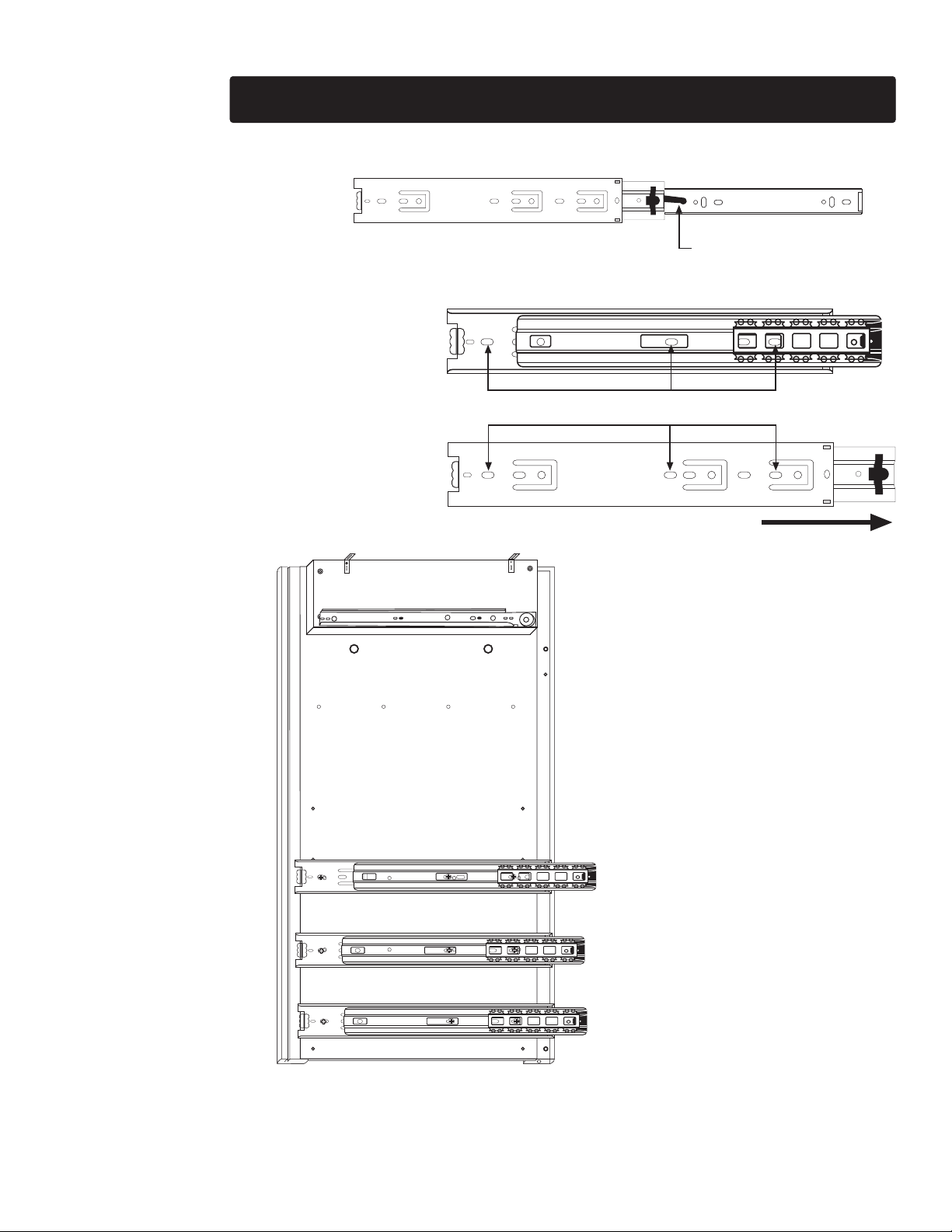
STEP 1B IMPORTANT - Please read these instructions carefully!
1. Remove the drawer side section of
the glide by pressing the black lever and
sliding the steel inner glide section all
the way out of the glide assembly. Set
this inner section aside as it will be used
later on the wine rack braces.
2. Next, identify the holes to be used for
attaching each glide to the side panel.
IMPORTANT as shown below, the full
extention glides are only attached to the
right side panel and the center divider
as seen in step 6.
Attach glides using 3/8 #6 pan head
screws. But do not tighten down the
screws. You must attach the back
panel in the next step, then shift the
glides all the way back so they are
flush with the back panel before
tightening into place. This will insure
that they are all even.
Face of
Glide
Use these three (3) holes to attach the glide to the side panel.
Backside
of Glide
FRONT OF CART
TOP
Press this lever then slide the
inner glide section out of the
glide assembly.
This edge will attach to
back panel in Step 7.
ILLUSTRATION 1B
Page 6
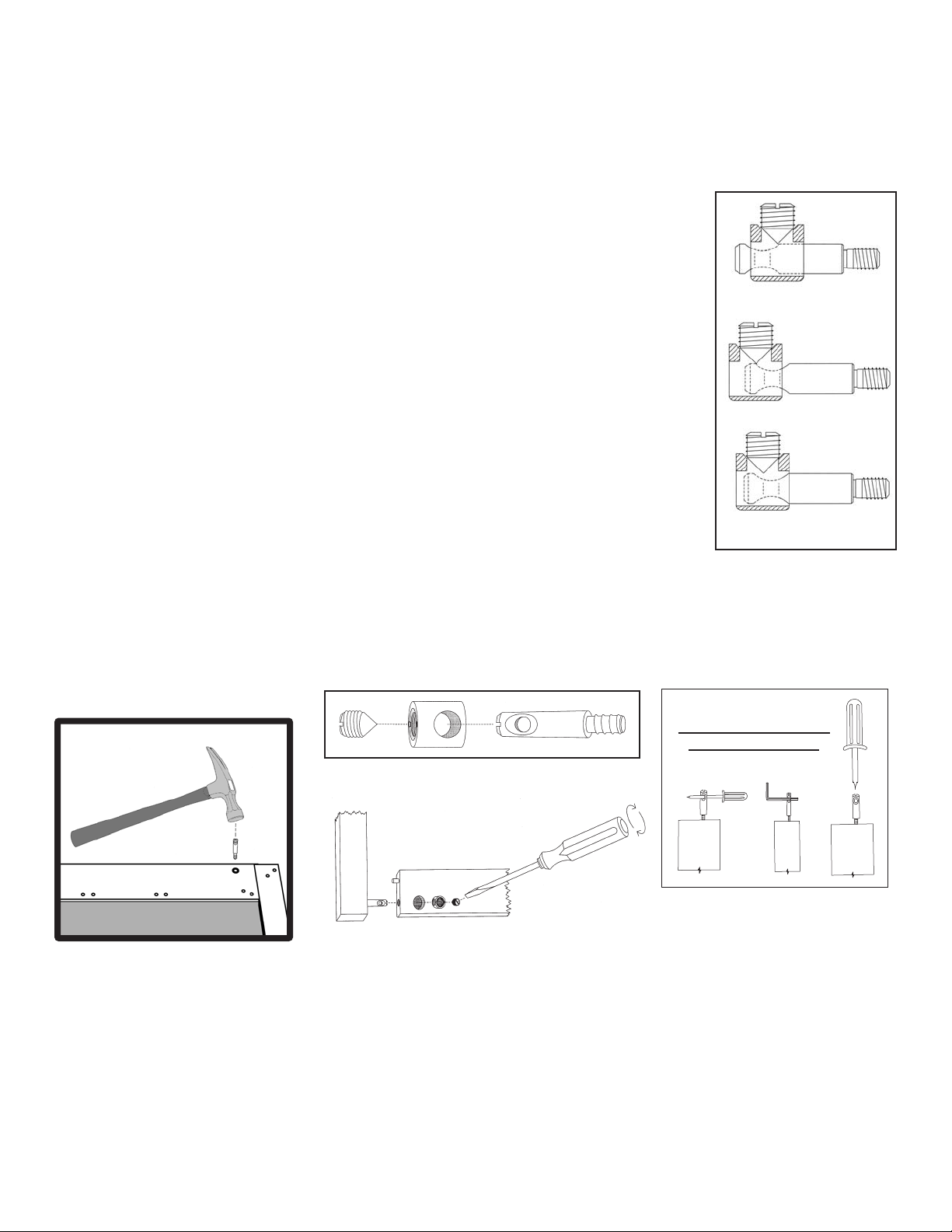
TIPS ON HOW THE BASTION FASTENING SYSTEM WORKS
1. The Bastion fastening system consists of a steel post (threaded on one end with a hole
through the shaft on the other end); a Barrel Nut (cylindrical barrel-shaped with threaded open
end & holes through the sides); and a Set Screw (Phillips slot on one end, pointed on the
other)
2. To attach Posts: A) Dip threads of Post in vegetable oil. B) Align threaded end of Post with
hole in wood, tap on slotted end with hard hammer until threads enter, then tighten down using
a flat head screw driver or the provided allen wrench (See the Illus. Bas. 3 for alternate seating
methods). DO NOT TRY TO HAMMER THE POST ALL THE WAY IN AS IT WILL STRIP THE
POST HOLE. C) When solid shaft of Post hits wood, back out approximately ½ turn until the
hole in the posts is properly aligned as per step by step directions. For example: the holes in
the posts on the inside of the drawer front will be parallel with the long length of the drawer
front when properly seated.
3. A) Place a Barrel Nut into the nut access hole, so that the threads in the nut face out. The
small notches on either side of the nut opening, indicate the location of the holes through the
sides of the nut. B) Insert the posts through the end of the braces (or drawer sides); through
the holes in the sides of the nut. When properly aligned, you will see the hole in the post inside
the barrel nut. Post hole should be slightly off-center toward the wood.
4. Insert the Set Screw into the threaded end of the nut and tighten down with a hand
screwdriver or allen wrench*. DO NOT USE A POWER SCREWDRIVER TO TIGHTEN THE
SET SCREWS. The tip of the Set Screw will seek the center of the hole in the Post as it is
tightened down, forcing the Nut toward the main shaft of the Post. This is what tightens the
wooden parts together. Set screws should thread easily DONT CROSS THREAD! If Set
Screw doesnt thread easily, check position of the hole in Post.
Illustration Bas. 1
WRONG!
Post needs to be screwed deeper.
WRONG!
Post needs to be backed out.
CORRECT!
Set screw secures post properly.
5. If the wooden parts are not tight against each other, the Post needs to be screwed a half
turn at a time until wood joints are tight.
Illustration Bas. 2
Step 1
Step 2
* NOTE: Some set screws have Phillips Heads, others may have hex heads. When Hex heads
are used, we will supply the allen wrench.
Illustration Bas. 3
ALTERNATIVE METHODS
FOR SEATING POSTS
If you have any questions regarding assembly or missing or damage
parts, call our customer support number:
607-652-7321 or 888-732-7321.
Customer Support hours are 8am-5pm Mon. - Fri. Eastern Time zone.
Page 7

STEP 2
A. Attach the Drawer Back to the Drawer Sides with four 1 1/4 #8 screws. There are left and
right sides. Make sure the slots that run the length of the Sides are aligned with the slot in the Drawer
Back to accept the Drawer Bottom.
B. Slide in Drawer Bottom, best side up, to inside of drawer.
C. Take the 2 bastion posts, align the threaded end of the posts with the post holes located
near the ends of the inside of the Drawer Front. Tighten posts down until the solid shaft of the posts
hits the wood. Back post out until the hole/screwdriver slot in end of post is parallel and in direct line
with the long edges of the Drawer Front.
D. Insert the barrel nuts into the nut access holes on the inside of the Drawer Sides with the
threaded ends of the nuts facing out. Take the Drawer Front and carefully insert the posts into the ends
of the Drawer Sides, through the sides of the nuts until seated. Push nut snug up against the wood in
the nut access hole toward the inside of Drawer Front. Hole should be slightly off-center toward the
Drawer Front. Insert the set screw and tighten down. The ends of the sides should be tight against the
inside Drawer Front.
E. Attach the drawer handles with 1 Truss head machine screws. Washers may be necessary to ensure a
snug fit.
F. Attach the drawer glides (left and right) to the Drawer Sides using two 5/8 #5 screws per
side. Wheels go toward Drawer Back and are up. The end with no wheels should touch the Drawer
Front.
4 Used
in this step
1-1/4 Phillips Flat Head #8 Screw
4 Used
in this step
1 Truss Head Machine Screw
4 Used
in this step
5/8 Phillips Flat Head
#5 Screw
ILLUSTRATION 5
2
4
3
1-1/4 #8 Screw
5/8 #5 Screw
1 Truss Head Machine Screw
Flat Washer (if necessary for tightening)
BASTION ASSEMBLY INSTRUCTIONS
DO NOT USE POWER SCREW DRIVER FOR THIS STEP.
USE HAND SCREW DRIVER ONLY.
1. Screw Bastion post into drawer front. Screw until all threads
are hidden, then back out a half turn (or the depth of a finger
nail) such that the hole in the post will face left to right.
1
2. Place the barrel nut into the side brace hole.
3. Slide the side brace onto the post such that the post also
slides into the barrel nut.
4. Screw the set screw into place, tightening such that the
side brace and drawer front pull together tightly.
Page 8

STEP 3
A. Attach rack front to the rack sides using bastions. (See bastion assembly
instructions below for added information.)
B. Insert wine bottle support dowels into rack fronts and backs.
C. Secure rack back to sides using 1-1/4 #8 screws (4 used in this step).
D. Attach inner rack glide to rack sides using 3/8 #6 pan head screws.
Rack glide should be flush with the rack front.
12 Used in this step
1-1/4 Phillips Flat Head #8 Screw
Rack Back
12 Used
in this step
3/8 Pan Head #6 Screw
Open end of
glide faces
the back
3
1
2
4
Rack Front
BASTION ASSEMBLY INSTRUCTIONS
1. Screw Bastion post into wine rack front. Screw until all
threads are hidden, then back out a half turn (or the depth of
a finger nail) such that the hole in the post will face left to
right.
2. Place the barrel nut into the side brace hole.
3. Slide the side brace onto the post such that the post also
slides into the barrel nut.
4. Screw the set screw into place, tightening such that the
side brace and wine rack front pull together tightly.
Page 9

STEP 4
A. Tap/insert ONE 1 1/2 pin into each end of the door. DONT OVERDRIVE PINS! Pins should stick
up about 1/2 when seated.
B. Attach the magnet plate (may be stuck to magnet in the hardware pack!) with the 1/2 #4 screw
to the top of the door. Bumps go toward the wood, and the plate should be vertical.
C. Attach door handle with 1 truss head machine screws.
fit.
Washers may be necessary to ensure a snug
2 Used
in this step
1 Truss Head Machine Screw
2 Used
in this step
1 1/2 Long 3/16 DIA. Steel Pin
2 Used
in this step
3/16 Flat Washer
ILLUSTRATION 4
STEP 5
A. Take the 2 front braces and tap/insert one 3/4 steel pin into each end of both braces until
seated. About 3/8 will stick out when seated. OK if loose.
4 Used
in this step
3/4 Long 3/16 DIA. Steel Pin
ILLUSTRATION 5
Page 10

STEP 6
A. Tap/insert 3/4 pin into each edge of the center divider. DONT OVERDRIVE PINS! Pins
should stick up about 1/4 when seated.
B. Attach the magnet with the 1/2 #4 screws to the top of the panel.
C. Attach full extention glides to the center divider as shown. Note that the glides should
slide out towards the same edge with the attached magnet.
D. Tap 1 steel pins into the left side of the center divider to be used as shelf supports in a
later step.
4 Used
in this step
3/4 Long 3/16 DIA. Steel Pin
4 Used
in this step
1 Long 3/16 DIA. Steel Pin
1 Pin
Left Side View
3/4 Pin
This edge faces
the front of the
cart
Right Side View
3/8 Phillips
Pan Head
#6 Screw
ILLUSTRATION 6
9 Used
in this step
3/8 Phillips Pan Head #6 Screw
Page 11

STEP 7
A. Lay Back Panel flat on a smooth surface with holes up.
B. Attach Side Panels with 1 3/4 machine screws (bolts) and hex nuts. After inserting bolts(s) thru the
holes in the Side Panels, thru the holes in the edges of the Back Panel, place a hex nut on the tip
of your finger, align nut with bolt and tighten.
C. Look ahead to step 8 which shows side panels attached to back panel.
NOTE: Make sure you position the side panels according to Drawer Glides (left or right).
And that the Back Panel is 1 1/4 shorter than the Side Panel at the top.
4 Used
in this step
1 3/4 Phillips Flat Head Bolt
4 Used
in this step
10-24 Hex Nut
ILLUSTRATION 7
STEP 8
A. Place the center divider pins into the
holes on the back panel.
B. Attach the front brace using 1-3/4 flat
head bolts and hex nuts.
C. Push the glides back flush against the
backpanel and tighten the screws on
both the side panel and the center divider.
ILLUSTRATION 8
2 Used
in this step
10-24 Hex Nut
2 Used
in this step
1 3/4 Phillips Flat Head Bolt
Page 12

STEP 9
A. Install Door by placing a washer onto
the pin on the bottom of the door, then
sliding the pin into the hole in the bottom
Front Brace.
B. Fit the top Front Brace onto the pin on
the top of the door and secure the brace
using 1 3/4 machine screws and nuts as
in illustration 9A.
C. Tap 1 pins into left Side Panel as in
illustration 9B. These will hold the shelves.
ILLUSTRATION 9A
4 Used
in this step
1 Long 3/16 DIA. Steel Pin
2 Used
in this step
10-24 Hex Nut
ILLUSTRATION 9B
2 Used
in this step
1 3/4 Phillips Flat Head Bolt
Page 13

STEP 10
Invert unit or lay the unit on its back
to insert the wheels. USE A FRIEND
TO HELP WITH THIS PROCESS.
A. Insert and tap caster sockets with
hammer until the teeth grab the
wood. DONT POUND SOCKET
FLAT OR CASTER SHAFT WILL
NOT ENTER.
B. Insert casters and seat by pushing
straight downward with heel of your
hand, or tap into place with a
hammer. Dont be afraid to give them
a good downward whack on the solid
metal part of the caster!
C. Locking wheels usually go on
front.
ILLUSTRATION 10
STEP 11
A. Upright unit. USE A FRIEND TO HELP WITH THIS PROCESS.
B. Attach Towel Bars to the Side Panels with 1 1/4 #8 screws from inside each Side Panel.
1-1/4 #8 screws
4 Used in this step
1-1/4 Phillips Flat Head #8 Screw
ILLUSTRATION 11
Page 14

STEP 12
A. Assemble top by placing the top and the drop leaf upside down on a smooth flat surface. Install
hinges using 5/8 #8 screws. The longer part of the hinge goes on the drop leaf with the short part on
the cart top. Fasten the drop leaf supports using 5/8 #8 screws. See illustration 12B.
B. Make a large ( X ) mark over each of the 4 pilot holes in the bottom. Make marks about 1/2-1 long.
These marks will help you align the cabinet with the pilot holes in the bottom of the Top.
C. Place the Cart Top on the cabinet. Open the outside doors. Maneuver the Cart Top so that the ( X )
marks/pilot holes in the bottom of the Top align with the holes in the L brackets. Secure top to L
brackets with 5/8 #6 screws.
5/8 #8 screws
ILLUSTRATION 124A
20 Used
in this step
5/8 #6 screws
To attach L
Brackets
5/8 Phillips Flat Head
#8 Screw
4 Used
in this step
5/8 Phillips Flat Head
#6 Screw
STEP 13
A. Insert one 3/4 pin into the end of each
stemware holder. Orient holder as shown in
the illustration and put pins into holes in the
back panel.
B. Attach the stemware holders to the bottom
edge of the top front brace using 1 #8 screws.
ILLUSTRATION 12B
3/4 Long 3/16 DIA. Steel Pin
4 used in this step
3/4 Long 3/16 DIA. Steel Pin
4 used
in this step
1 Phillips Flat Head #8 Screw
1 Phillips
Flat Head
#8 Screw
ILLUSTRATION 13
Page 15

STEP 14
Slide the wine racks into place. To
initially seat the glides, it will take
some force. Once the glides are
properly seated, the wine racks
should pull out and slide in with ease.
ILLUSTRATION 14
STEP 15
A. Tilt the bottom shelf and set
down onto the pins.
B. Fit the middle shelf into the
cart and rest it on the pins. Edge
banding should face out of the
open cabinet.
ILLUSTRATION 15
Page 16

STEP 16
A. Slide the Drawer into the front of the cart.
B. Tap in the 5/8 wooden plugs into the holes on the legs.
C. Illustration 16B shows completed 1582.
ILLUSTRATION 16A
ILLUSTRATION 16B
Page 17

4/29/10
For continued beauty and long life of
your Catskill Craftsmen cart, we
recommend Catskill Craftsmens Butcher
Block Oil.
If you would like to purchase Butcher
Block Oil directly from Catskill Craftsmens
factory, we offer a reduced price. For one
eight ounce (8 fl. oz.) bottle, which is
sufficient for two applications, simply send
$5.95 along with the completed coupon to
the address below.
Catskill Craftsmen, Inc.
CRAFTSMEN, INC.
15 West End Ave.
Stamford, NY 12167-1296
CRAFTSMEN, INC.
BUTCHER BLOCK OIL COUPON
Please send me _____# of bottle(s) of the
Catskill Craftsmen Butcher Block Oil at $5.95.
My Check or Money Order is enclosed for a
total of $______________.
Item Code: 1582
NAME ______________________________________
ADDRESS __________________________________
___________________________________________
CITY ______________________________________
STATE _________________________ ZIP _______
Please make checks payable to: Catskill Craftsmen Inc.
 Loading...