

Page 1
CRAFTSMEN, INC.
Assembly Instructions
Model 1526
Microwave Space Saver Cart With Drawer
GENERAL:
1. You have purchased model 1526. Overall dimensions of an assembled unit is 24” x 17” x 53”
2. Should you need assistance or need to replace a damaged or missing part, DO NOT
RETURN THE UNIT TO THE STORE where you purchased it, simply give us a call and we’ll
send you the prepaid part via UPS usually that same day!
3. Read the assembly instructions and the enclosed brochure before beginning assembly.
Assembly is very easy if you read and follow the instructions step by step.
4. Tools required: Phillips screwdrivers, medium and small; medium flat blade screwdriver and
Page 2
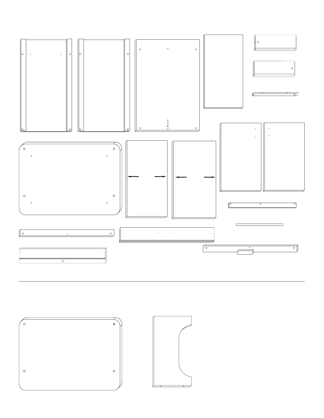
CABINET PARTS
TOP TOP
Handle Side Panel (1)
TOP
Plain Side Panel (1)
Not Used
Back Panel (1)
13 3/8”
Drawer Side Left (1)
Drawer Side Right (1)
Table Top Stick (2)
Drawer Bottom (1)
13 13/16”
Cabinet Top(1)
Bottom Brace (1)
Drawer Back (1)
RACK PARTS
Middle Shelf (1)
Drawer Front (1)
Bottom Shelf (1)
Left Door (1)
Door Spacer (1)
Drawer Dowel (1)
Top Brace (1)
Right Door (1)
Rack Side Panels (2) Rack Top(1)
Page 3
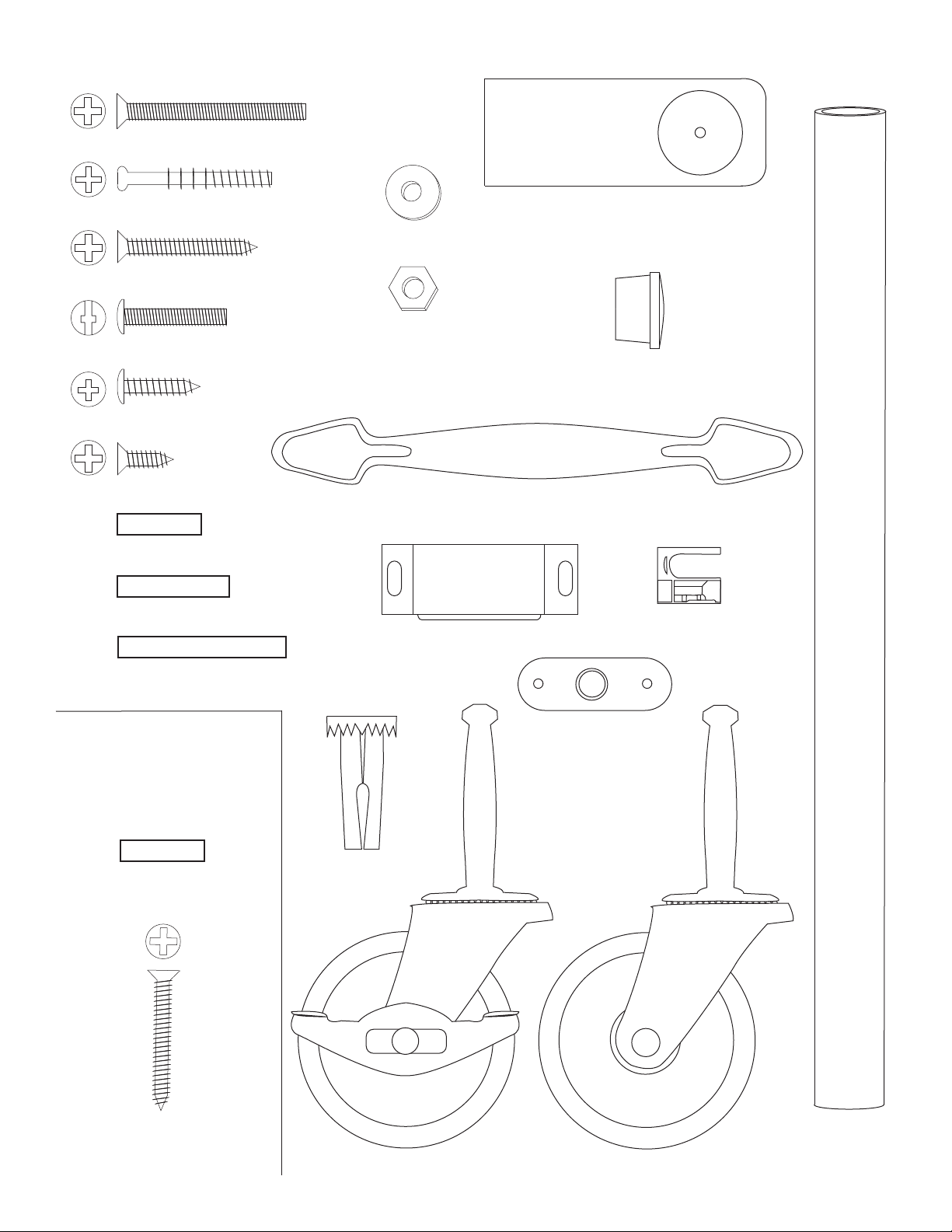
CABINET HARDWARE
1 3/4” Phillips Flat Head Machine Screw (8)
Cam Posts (2)
3/16” Flat Washer (2)
1 1/4” Phillips Flat Head #8 Screw (14)
10-24 Hex Nut (8)
1” Truss Head Machine Screw (6)
5/8” Pan Head Screw (2)
1/2” Phillips Flat Head #4 Screw (1)
3/4” Long 3/16” DIA. Steel Pin (4)
1” Long 3/16” DIA. Steel Pin (4)
Nickel Handle (3)
Magnet (1)
Towel Bar Post (2)
5/8 Wooden Disk (10)
Cam (2)
1 1/2” Long 3/16” DIA. Steel Pin (4)
RACK
HARDWARE
3/4” Long 3/16” DIA.
Steel Pin (4)
1 1/4” Phillips Flat Head
#8 Screw (8)
Caster Socket (4)
Locking Wheel Caster (2)
Magnet Plate (1)
Non Locking Wheel Caster (2)
Polished
Nickel Towel
Bar (1)
Page 4
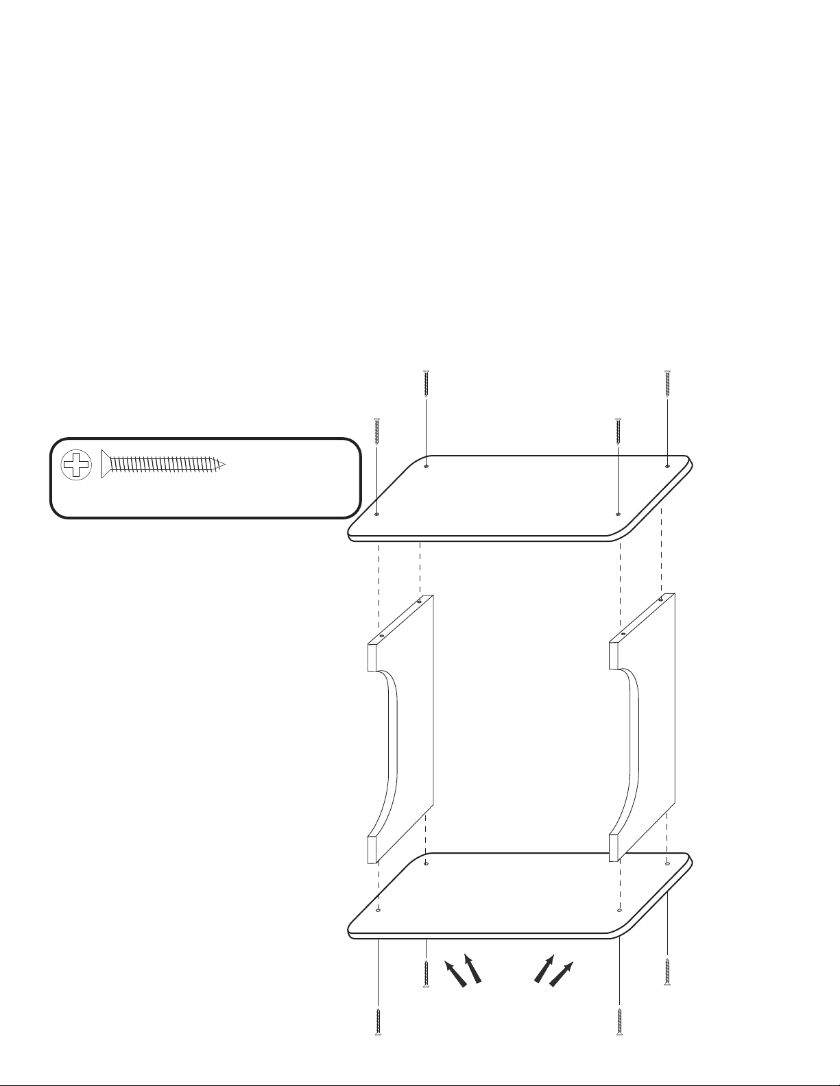
STEP A
1. Attach the Rack Top to the top ends of the Side Panels using 1 1/4” #8 wood screws. MAKE
SURE YOU HAVE THE RACK TOP! The only difference between the Rack Top and the Cabinet Top
is that the Cabinet Top has 4 small pilot holes on the bottom side plus the 4 throughholes; whereas,
the Rack Top only has the 4 through holes. NOTE: On the Rack Top the countersunk (reamed out)
through holes face up and the countersunk holes/pilot holes on the Cabinet Top face down.
The countersunk holes allow the screw heads to be flush with the wood surface when tightened down.
2. Turn this assembly upside down so that the Rack Top is on a smooth flat surface. Attach the
Cabinet Top with four 1 1/4” #8 wood screws. With the unit upside down at this point, the 4 pilot holes
should be up.
3. Leave this assembly UPSIDE DOWN and go to STEP 1. Looking ahead to STEPS 3 & 4,
the bottom of the Cabinet Top IS THE BOTTOM OF THE CART TOP ATTACHED TO THE RACK IN
STEP A4 ABOVE.
NOTE: The cart cabinet will be constructed
upside down using the bottom of the Cart
Top as the base.
8 Used in this step
1 1/4” Phillips Flat Head #8 Screw (22)
ILLUSTRATION A
RACK TOP
CABINET TOP
PILOT HOLES HIDDEN
Page 5

STEP 1
4 Used in this step
Attach a table top stick to the
top of each side panel using
1 1/4” #8screws. The countersunk
holes (reamed out) in the
stick are positioned as in
illustration 1. Sticks should
be flush with top of panel.
ILLUSTRATION 1
1 1/4” Phillips Flat Head #8 Screw (12)
STEP 2
A. Lay back panel flat on a smooth surface with holes up.
B. Decide at this point if you want the handle/towel bar on
the right or the left side of the cabinet as side panels are
interchangeable. We placed the handle/towel bar on the
right for these instructions.
C. Attach side panels with 1 3/4” machine screws (bolts)
and hex nuts. After inserting bolts(s) thru the holes in the
side panels, thru the holes in the long edges of the back
panel, place a hex nut on the tip of your finger, align nut
with bolt and tighten.
D. Look ahead to step 4 which shows side panels
attached to back panel.
4 Used
in this step
1 3/4” Phillips Flat Head Bolt (8)
4 Used
in this step
10-24 Hex Nut (8)
NOTE: Back panel is flush with bottom of side
panels. Back panel is 1” shorter than side
panels which leaves gap for drop leaf hinges.
STEP 3
STEPS 3 - 14 WILL BE ACCOMPLISHED WITH THE
UNIT TOP UPSIDE DOWN ( INVERTED ), BUILDING
UPWARD TOWARD THE BOTTOM/CASTER END!
BE CAREFUL AS PART DESCRIPTIONS ARE BASED
ON AN UPRIGHT, COMPLETED UNIT!
Mark a Large (X) mark over each of the 4 pilot holes
in the bottom. Make marks about 1 1/2” long. These
marks will help you align the cabinet with the pilot
holes in step 4.
ILLUSTRATION 2
ILLUSTRATION 3
Page 6

STEP 4
A. Turn the side/back assembly ( from step 2 ) upside down ( invert ) on top of the inverted table top.
B. Drop two 1 1/4” # 8 screws into the holes in each of the table top sticks.
C. Using the (X) marks from step 3 as a guide, insert the tips of the screws into the pilot holes in the
unit top and finger tighten. When all 4 screws are properly aligned, tighten down.
D. Tap two 1” pins into each side panel. These pins will hold the bottom shelf. See illustration 4
4 Used in this step
1 1/4” Phillips Flat Head #8 Screw (12)
4 Used in this step
1” Long 3/16” DIA. Steel Pin (8)
ILLUSTRATION 4
PIN
PIN
Page 7

STEP 5
A. Attach the drawer back to the drawer sides with
four 1 1/4” #8 screws. Make sure parts are aligned
as in illustration 5A.
B. Insert drawer bottom into the slots in the drawer
sides, best side to inside of drawer. Slide down
until seated in the slot in the drawer back.
See illustration5B.
C. Screw the cam posts into the two outside holes
on the inside face of the drawer front until seated.
Only 3/8” of this post goes into the wood, leaving
the 4 guide rings/head exposed. See illustration 5C.
D. Insert the posts into holes in the drawer side
until seated against the front ends of the drawer
sides. Insert cams so that slot in the cam fits over
the post and turn with Phillips screwdriver until
seated. Don’t over-torque! See illustration 5D.
E. Attach drawer handle with the two handle
screws ( no illustration ).
ILLUSTRATION 5A
ILLUSTRATION 5C
Below line in wood
Cam Posts (2)
4 used
in this step
1 1/4” Phillips Flat Head #8 Screw (4)
2 used
in this step
1” Truss Head Machine Screw (6)
2 used
in this step
Cam (2)
ILLUSTRATION 5B
ILLUSTRATION 5D
Page 8

STEP 6
Take drawer, insert the drawer
dowel thru the hole in the
drawer back, invert drawer
and place in cabinet cavity.
Insert/turn drawer dowel
into the 1/2” dia. hole in
the back panel.
ILLUSTRATION 6
STEP 7
Take the 2 front braces and tap/insert one 3/4” steel pin
into each end of both braces until seated. About 3/8”
will stick out when seated. Ok if loose.
4 used in this step
3/4” Long 3/16” DIA. Steel Pin (4)
ILLUSTRATION 7
Page 9

STEP 8
A. Take the top front brace ( with magnet block ), insert the pins in the brace
ends into the slots on the inside of the front legs and slide down until the
brace rests on the bottom of the drawer front. The pin holes for the door
pins will be up.
B. Twist drawer dowel into the 1/2” dia.
hole on the inside of the brace under
the magnet block.
C. BEFORE securing brace with
1 3/4” machine screws/hex nuts,
raise brace approximately 1/8”
before tightening ( or use a
couple of dull kitchen knives
as spacers between the brace
and the top edge of the
drawer front. ) This will allow
the drawer to open easily
Hex Nut
Inside Brace
Nut Access Hole
ILLUSTRATION 8B
Side Panel Leg
Countersunk Hole in Leg
( disk goes in this hole to
hide bolt head! )
1 3/4” Phillips Flat Head Bolt (8)
ILLUSTRATION 8A
2 Used
in this step
10-24 Hex Nut (8)
2 Used
in this step
Page 10

STEP 9
Attach handle/towel bar to side panel with 1 1/4” #8 screws from inside side
2 Used in this step
1 1/4” Phillips Flat Head #8 Screw (12)
ILLUSTRATION 9
STEP 10
A. Tap/insert ONE 1 1/2” pin
into each end of both doors.
DON’T OVERDRIVE PINS!
Pins should stick up about
1/2” when seated.
B. Attach the doorspacer to
the left door with 5/8” #8
screws. The spacer has a
space at the top to allow
magnet clearance and is
almost flush with the bottom
of the door. Countersunk
holes out.
C. Attach the magnet plate
(may be stuck to magnet! )
with the 1/2” #4 screw to
the top of the right door.
Bumps go toward the wood.
D. Attach door handles with
1” truss head machine
screws.
ILLUSTRATION 10
4 used in
this step
1 1/2” Long 3/16” DIA. Steel Pin (4)
2 used
in this step
1” Truss Head Machine Screw (6)
Magnet Plate (1)
3 used in this step
5/8” Phillips Flat Head #8 Screw (23)
1 used in this step
1/2” Phillips Flat Head #4 Screw (1)
Page 11

STEP 11
A. Install doors by inserting pins in
the door tops into the holes in
the long edge top front brace.
B. Place one washer on
each of the door pins in
the door bottoms.
C. Take the bottom front
brace, align pins in door
bottoms with holes along
top long edge of brace
( are washers on pins ? )
and secure brace with
1 3/4” Machine screw/hex nuts
as before.
2 Used
in this step
10-24 Hex Nut (8)
2 Used
in this step
3/16” Flat Washer (2)
ILLUSTRATION 11
1 3/4” Phillips Flat Head
Machine Screw (8)
2 Used in this step
STEP 12
A. Stick magnet to magnet plate on right door.
B. With left door open, close the right door. The magnet should be positioned over the wooden block
on the bottom of the top front brace. Hold the magnet in place with your thumb, and open the right
door. The magnet will be in the correct position on the block.
C. Secure magnet with the two round head screws in the magnet packet. Center screws in the slots in
the magnet . This will allow adjustment later, if needed.
NOTE: No pilot holes in block, as softwood!
2 Used
in this step
ILLUSTRATION 12
5/8” Pan Head Screw (2)
Magnet (1)
Page 12

STEP 13
A. Insert and tap caster sockets with
hammer until the teeth grab the wood.
DON’T POUND SOCKET FLAT
OR CASTER SHAFT WILL
NOT ENTER.
B. Insert casters and seat by
pushing straight downward
with heel or your hand, or tap
into place with a hammer.
Don’t be afraid to give them
a good downward whack on
the solid metal part of the
caster!
C. Locking wheels usually go
on back, but can go diagonally
or on the front if cart is moved
a lot.
ILLUSTRATION 13
STEP 14
A. Upright Unit. Take bottom
shelf ( no edge banding )
and place it on the set of
back pins. Close doors
and shelf will drop into
place.
B. Decide on position
of middle shelf, then
tap two 1” pins into each
side panel, making sure the
pins on both sides are in the
same relative position. To
remove a pin, use pliers or
claw hammer.
C. Place middle shelf, edge
banding out, on pins.
D. Tap wooden disks
into sides.
ILLUSTRATION 14
Page 13

012208
For continued beauty and long life of
your Catskill Craftsmen cart, we
recommend Catskill Craftsmen’s Butcher
Block Oil.
If you would like to purchase Butcher
Block Oil directly from Catskill
Craftsmen’s factory, we offer a reduced
price. For one eight ounce (8 fl. oz.)
bottle, which is sufficient for two
applications, simply send $6.95 along
with the completed coupon to the
address below. If you prefer to use
MasterCard or Visa visit us online at
www.catskillcraftsmen.com.
Catskill Craftsmen, Inc.
CRAFTSMEN, INC.
15 West End Ave.
Stamford, NY 12167-1296
CRAFTSMEN, INC.
BUTCHER BLOCK OIL COUPON
Please send me _____# of bottle(s) of the
Catskill Craftsmen Butcher Block Oil at $6.95.
My Check or Money Order is enclosed for a
total of $______________.
Item Code: 1526
NAME _____________________________________
ADDRESS __________________________________
__________________________________________
CITY ______________________________________
STATE _________________________ ZIP _______
Please make checks payable to: Catskill Craftsmen Inc.
15 West End Ave. Stamford, NY 12167-1296
 Loading...