

Page 1
Assembly Instructions
Model 1480DOR
Empire Island
GENERAL:
1. You have purchased model 1480DOR.
2. Should you need assistance or need to replace a damaged or missing part simply give us a call M-F
at 607-652-7321 from 7:30 am - 4:30 pm Eastern and we’ll send you the prepaid part via UPS usually
that same day! You may also email us: info@catskillcraftsmen.com.
3. Read the assembly instructions and the enclosed brochure before beginning assembly. Assembly is
easy if you read and follow the instructions step by step. See our website for assembly tips and videos:
www.catskillcraftsmen.com
4. The only tools needed are a hammer, a small and a medium Phillips head screwdriver and a medium
at blade screwdriver. A pencil is also needed. A power screwdriver will speed assembly, but is not
required. Place a few drops of vegetable oil on the threads of wood screws before screwing into the
solid hardwood parts.
5. Glides are sometimes pre-packed with screws. These are not used.
6. Instructions (left/right, top/bottom) are given as you face an assembled unit.
Page 2
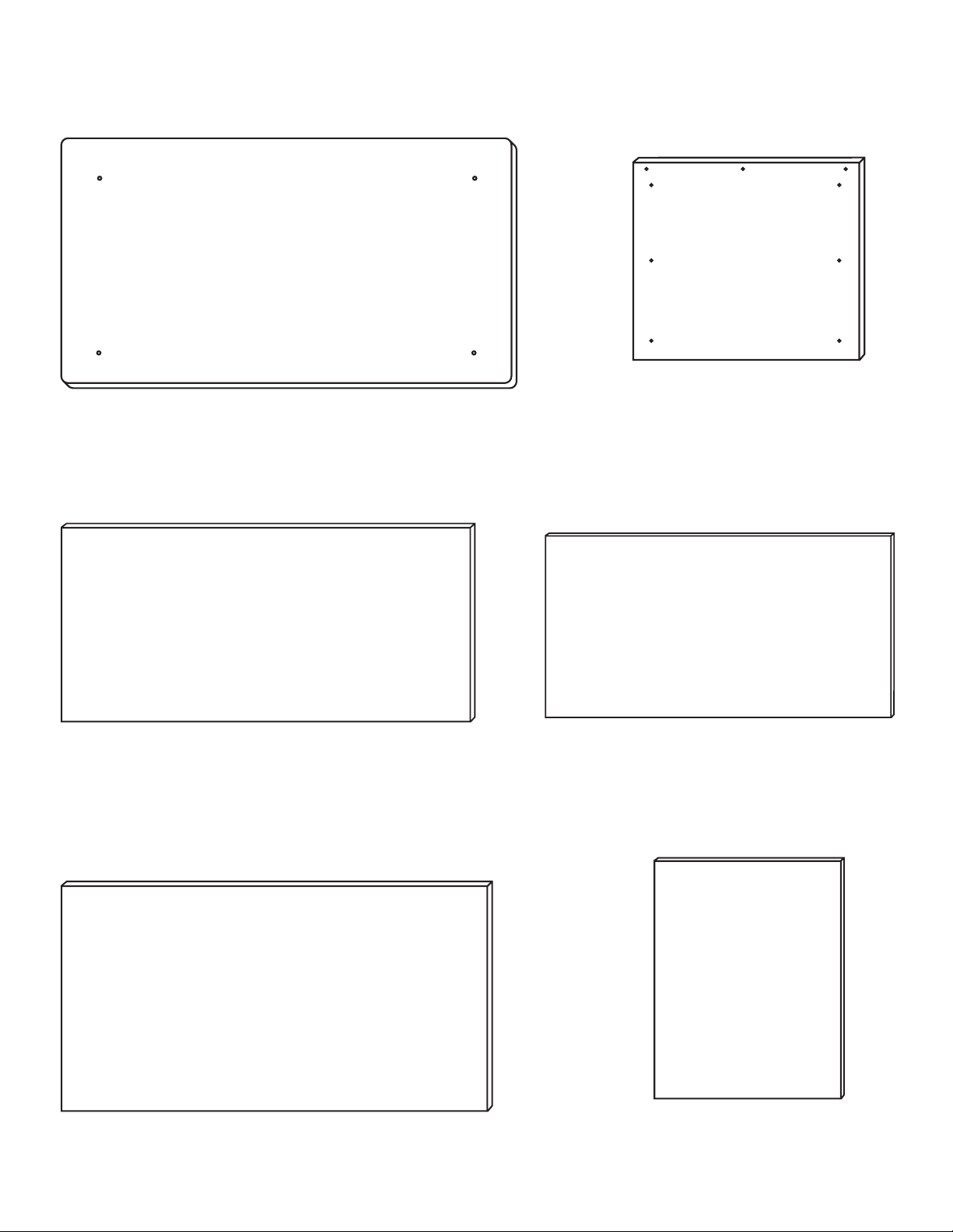
CABINET PARTS
Not To Scale
BOTTOM VIEW
(1) Table Top-1480
44” x 26” x 1 1/4”
BOTTOM VIEW
(2) Pull Out Cutting Board Tops
22” x 19 1/2” x 3/4”
(1) Bottom Shelf-1480
39 3/16” x 22 1/8” x 7/16”
(1) Middle Shelf-1480DOR (Edge Banded)
39 3/16” x 21 7/16” x 7/16”
(1) Drawer Bottom-1480
31 9/16” x 21 3/4” x 1/4”
(2) Side Panel Inserts-1480
20 9/16” x 22 11/16” x 1/4”
Page 3
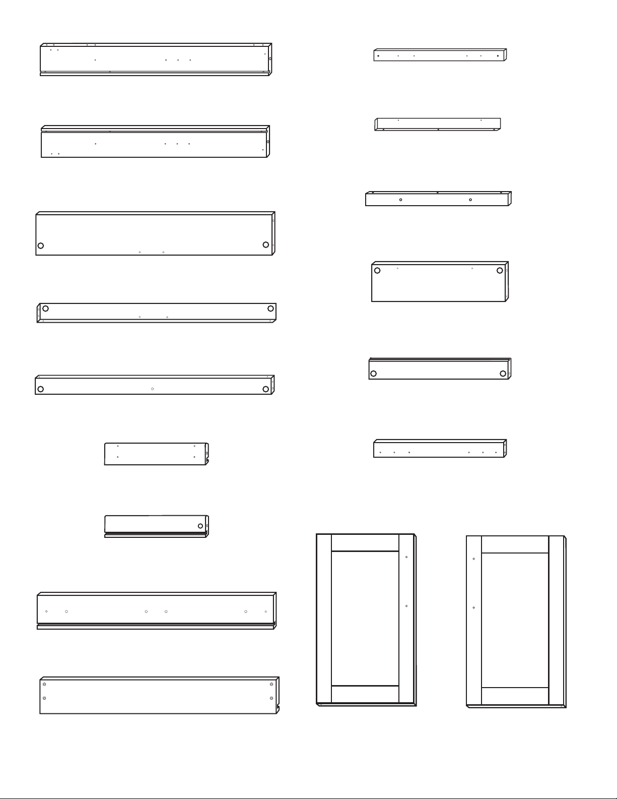
(2) Right Leg-1480DOR
32 1/2” x 4” x 7/8”
(Inside View)
(2) Left Leg-1480DOR
32 1/2” x 4” x 7/8”
(Inside View)
(1) Top Back Brace-1480DOR
33 7/16” x 7 3/8” x 3/4”
(Inside View)
(1) Top Front Brace-1480DOR
33 7/16” x 2” x 3/4”
(Inside View)
(4) Cutting Board Glide Support-1480DOR
19” x 3/4” x 3/4”
(Inside View)
(4) Cutting Board Side Rail-1480DOR
18” x 1 1/4” x 3/4”
(Inside View)
(2) Cutting Board Front-1480DOR
21 3/4” x 2” x 3/4”
(Inside View)
(2) Top Side Brace-1480DOR
22 1/4” x 5 1/8” x 3/4”
(Inside View)
(2) Front/Back Bottom Brace-1480DOR
33 7/16” x 2” x 3/4”
(Inside View)
(1) Left Drawer Side-1480DOR
21 1/4” x 4 3/8” x 3/4”
(Outside View)
(1) Right Drawer Side-1480DOR
21 1/4” x 4 3/8” x 3/4”
(Inside View)
(1) Drawer Front-1480DOR
33 1/4” x 5 3/16” x 3/4”
(Inside View)
(4) Mid/Bot Side Brace-1480DOR
22 1/4” x 2 1/4” x 3/4”
(Inside View)
(2) Drawer Glide Support-1480DOR
22 1/4” x 1 1/2” x 3/4”
(Outside View)
(1) Drawer Back-1480DOR
32 7/16” x 4 3/8” x 3/4”
(Outside View)
(2) Right Door -1480DOR
22 1/4” x 16 5/8” x 3/4’
(Inside View)
(2) Left Door-1480DOR
22 1/4” x 16 5/8” x 3/4”
(Inside View)
Page 4
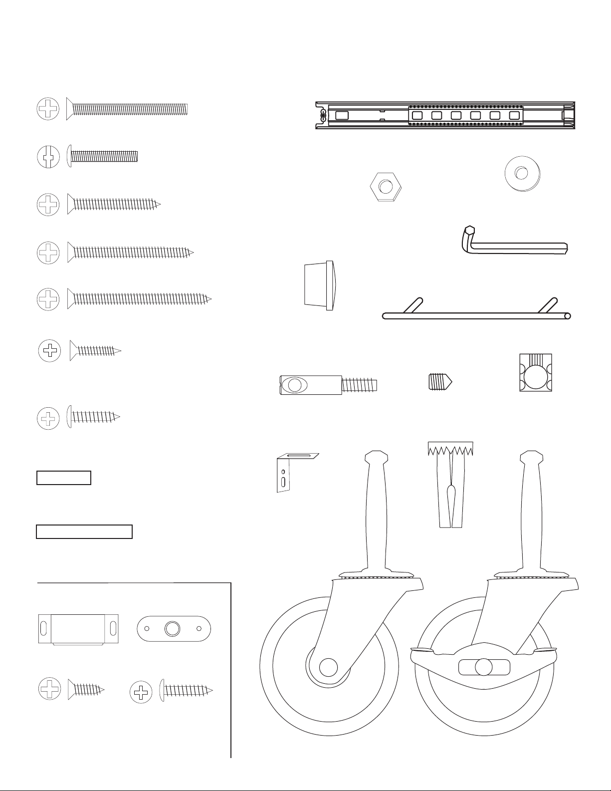
HARDWARE
1 3/4” Phillips Flat Head Bolt (12)
MSKRU M5-25 For Handles (16)
(Drawer Back &
Cutting Board Glide Support)
1 1/4” Phillips Flat Head #8 Screw (12)
(Attaches Cutting
Board Side Rails)
1 3/4” Phillips Flat Head #8 Screw (12)
(Attaches Cutting
Board Fronts)
2 1/2” Phillips Flat Head #8 Screw (6)
5/8 Wooden
Disk (12)
Note: Not to scale
18” Full Ext Glide Sets (3)
1/2” Flat Washer (16)
10-24 Hex
Nut (12)
Allen Wrench
Bar Handle (8)
”L” Bracket Screws
5/8” Phillips Flat Head #6 Screw (8)
Glide Screws
7/16” Phillips Pan Head #6 Screw (24)
3/4” Long 3/16” DIA. Steel Pin (20)
(Brace Ends and Glide Suports)
1 1/2” Long 3/16” DIA. Steel Pin (18)
(Shelf Supports and Doors)
MAGNET PACK
Magnet (4)
Magnet Plate (4)
Bastion Post (10)
“L” Bracket (4)
Bastion
Set Screw (10)
Caster Socket (4)
Bastion
Barrel Nut (10)
1/2” Phillips
Flat Head
#4 Screw (4)
5/8” Pan Head
Screw (8)
Caster with Stops (2) Caster (2)
Page 5
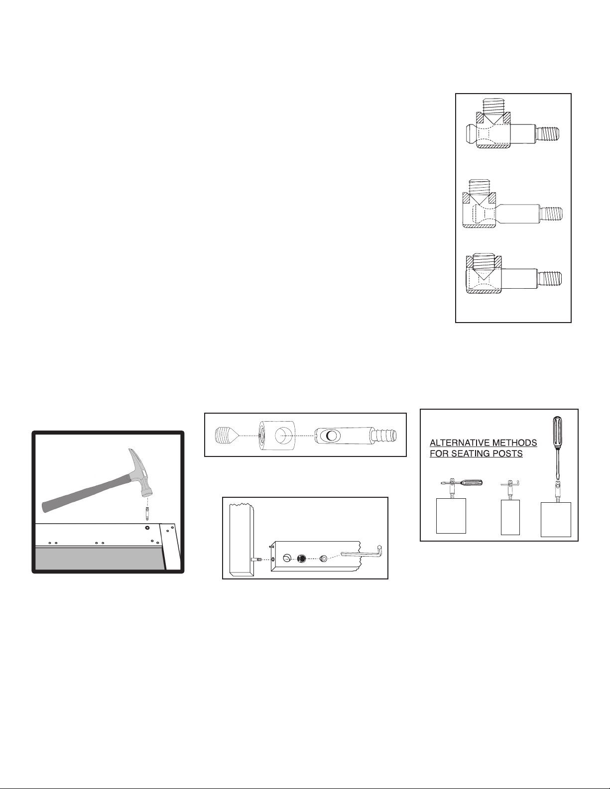
1. The Bastion fastening system consists of a steel post (threaded on one end with a hole
TIPS ON HOW THE BASTION FASTENING SYSTEM WORKS
through the shaft on the other end); a Barrel Nut (cylindrical barrel-shaped with threaded
open end & holes through the sides); and a Set Screw (Phillips slot on one end, pointed on
the other)
2. To attach Posts: A) Dip threads of Post in vegetable oil. B) Align threaded end of Post
with hole in wood, tap on slotted end with hard hammer until threads enter, then tighten
down using a flat head screw driver or the provided allen wrench (See the Illus. Bas. 3 for
alternate seating methods). DO NOT TRY TO HAMMER THE POST ALL THE WAY IN AS IT
WILL STRIP THE POST HOLE. C) When solid shaft of Post hits wood, back out
approximately 1 turn until the hole in the posts is properly aligned as per step by step
directions. For example: the holes in the posts on the inside of the drawer front will be
parallel with the long length of the drawer front when properly seated.
3. A) Place a Barrel Nut into the nut access hole, so that the threads in the nut face out.
The small notches on either side of the nut opening, indicate the location of the holes
through the sides of the nut. B) Insert the posts through the end of the braces (or drawer
sides); through the holes in the sides of the nut. When properly aligned, you will see the hole
in the post inside the barrel nut. Post hole should be slightly off-center toward the wood.
Illustration Bas. 1
WRONG!
Post needs to be screwed deeper.
WRONG!
Post needs to be backed out.
4. Insert the Set Screw into the threaded end of the nut and tighten down. The tip of the Set
Screw will seek the center of the hole in the Post as it is tightened down, forcing the Nut
toward the main shaft of the Post. This is what tightens the wooden parts together. Set
screws should thread easily – DON’T CROSS THREAD! If Set Screw doesn’t thread easily,
check position of the hole in Post.
5. If the wooden parts are not tight against each other, the Post needs to be screwed a half
turn at a time until wood joints are tight.
Illustration Bas. 2
Step 1
Step 2
Illustration Bas. 3
Set screw secures post properly.
CORRECT!
Allen Wrench Provided
See video on our website!
If you have any questions regarding assembly or missing or damaged
parts, call our customer support number:
607-652-7321 or 888-732-7321.
Customer Support Hours are 8am-5pm Mon. - Fri. Eastern Time zone.
Page 6
STEP 1
Push down on the black tab and pull out
Slide Out Cutting Board Assembly - Part 1
2 Pull Out Cutting Board Tops, 2 Cutting Board Fronts, 4 Cutting Board Sides.
Lay Pull Out Cutting Board Top on its
back so holes face up. Then attach
Counter Sink Up
the Cutting Board Front to the Top,
so that the counter sunk holes face up,
using 2 1/2” #8 screws (the curved edge
should face outward). Now attach the
Cutting Board Side Rails to the Top
so that the glide holes face out
and the counter sunk holes
face up, using 1 3/4”
#8 screws.
1 3/4” #8 Screws
STEP 2
Slide Out Cutting Board Assembly - Part 2
2 1/2” #8 Screws
Cutting Board Front
glide holes toward
the outside and
off center up
Tip: Dip screw tips in cooking oil
to ease turning into hardwood.
A. Take all of the glides and detach the inserts by fully extending the glides and pressing down on the
black tab and pulling them out.
B. Attach Glide Inserts to the sides of the Slide Out Cutting Boards using Two (2) 7/16” #6 Pan Head
Screws.
C. Attach Handles to the
Cutting Board Top
using M5-25 machine
screws. Glides should
be almost 1/8” to the front
Gets attached to the Drawer Side Gets attached to the Glide Support Brace
edge of the
Sides.
7/16” #6
Pan Head Screws
Note: Holes in glides sometimes vary.
about 1/8”
from drawer
front
Just make sure glides are about 1/8 inch
from front edge of the sides against inside
of Drawer Front.
Page 7

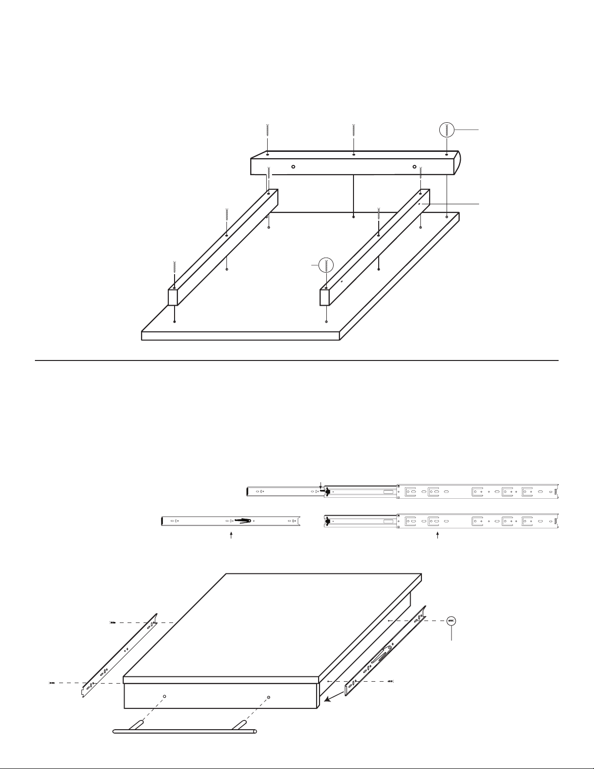
STEP 3
Drawer Assembly
2 Drawer Sides, 1 Drawer Back, 1 Drawer Front, 1 Drawer Bottom
Attach Drawer Back to Drawer Sides using 1 1/4” #8 screws, then insert Drawer Bottom into slots
best side up. Put Bastion Posts into Drawer Front & secure to Drawer Sides using Barrel Nuts & Set
Screws. Attach Handles using Pan Head M5-25 Machine Screws. Screw the Glide Inserts to the
Drawer Sides using 7/16” Phillips Pan Head #6 Screws. Glide inserts will be almost ush with the
inside of the Drawer Front when mounted.
1 1/4” #8 Screws
M5-25
7/16” #6 Pan Head Screws
Bastion Post
(Holes in posts will be horizontal with top/bottom
long edges of drawer front when seated)
Page 8

STEP 4
Brace Preparation
Insert 3/4” Pins into each end of the Top and Bottom Braces and Drawer Glide Supports.
OK if Pins are loose.
Top Back Brace
Top Front Brace
Front/Back Bottom Brace (2)
Drawer Glide Support Brace (2)
STEP 5
Leg Preparation
Insert Bastion Posts into the 2 sets
of Legs as illustrated.
Tighten the Bastion down all the
way, then back it out about 1 turn
so that the hole in the Bastion Post
is perpendicular to the long edge
of the Leg. See illustration or
video on Bastion System at
www.catskillcraftsmen.com.
Right Leg
Left Leg
Inside View
Bottom
Bottom
Page 9

STEP 6
Back Panel Assembly
Bastion Post
Front and Back
Panel Assembly
A. The Back Panel Assembly
consists of a Right and Left
Rear Legs, Top Back Brace,
Bottom Brace, a Left Door and
a Right Door. Insert 1 1/2 inch
Pins into the top and bottom
of the Right and Left Doors.
Be sure to add a Washer
over the Pins on the bot-
tom of the doors. Insert
the Bottom Door Pins into
the holes in the bottom
brace as illustrated. In-
sert the Pins in the top
of the doors into the
Top Back Brace
as illustrated.
3/4” Pin
3/4” Pin
1 1/2” Pin
A
Top Back Brace
A
Make sure washer is on the door pin
Note pin hole in center
Bottom Brace
A
A
B. Fasten the Legs to the one side top/bottom, then the other side using the Bastion Posts and Pins
already inserted in steps 4 and 5. Insert Barrel Nuts into the Nut Access Holes and tighten down with
Set Screws.
C. Repeat the entire process for the Front Panel Assembly.
3/4” Pin
Right Back Leg
B
Back Panel Assembly
Top Back Brace
Left Back Leg
B
Bastion Post
Note pin hole in center
Bottom Brace
Page 10

Back Panel Assembly
STEP 7
Attach Magnet Plates
Using 1/2” Phillips Flat Head #4 screws from your Magnet Pack attach the Magnet Plates to the small
pilot holes at the top of the Doors. Bumps on Plate go against wood.
1/2” Phillips Flat Head #4 Screw
Front Panel Assembly
1/2” Phillips Flat Head #4 Screw
Page 11

STEP 8
Insert Caster Sleeves
and Cutting Board Glides
A. Insert the Caster Sleeves into the holes in the bottom of the Legs and tap in with a hammer until
the teeth grabs the wood - don’t pound at! Repeat for the front assembly.
B. Attach the Magnets to the bottom inside edge of the Glide Supports using the round head screws
included in the Magnet Pack.
C. Attach the Glide Supports to the Top Back Brace using 1 1/4” #8 screws. Be sure to insert 3
Washers between the Glide Support and the Top Back Brace as illustrated below.
D. Attach the Cutting Board Glides using 7/16” #6 Pan Head Screws to the Cutting Board Glide
Support so that they extend to the outside of the cart. The front edge of the Glide is almost ush with
the front edge of the Glide Support as in the illustration. Two holes in the Glide Support are not used.
7/16” #6 Pan Head Screws
Not Used
Not Used
Pilot Holes for Magnet
1 1/4” #8 Screws
(Rounded)
5/8” Pan Head Screws
Page 12

STEP 9
1 3/4 machine screws
Brace Prep
A. Attach the Drawer Glides to the Glide Support
Sticks using two 7/16” #6 screws. Slide top part
of glide to expose pilot holes in glide support sticks.
The front edge of the glide will overhangthe front edge of the
Glide Support Stick by 1/8 inch. See Illustration 9A.
The Glide Sticks have 6 holes - only 2 are used. The pilot holes should be facing down and the glide
is slightly below the long edge of the stick when positioned properly.
B. Attach Bottom Side Braces (illustration 9B), Middle Side Braces, (illustration 9C) Top Side Braces
and drawer glide support sticks (illustration 9D) to the back assembly using 1 3/4 machine screws
and nuts. Position braces as illustrated.
Note: This step requires access to both sides of the back panel in order to insert the machine screws
(bolts) from the front & attach the nuts/braces on the inside with help. The easiest way is to invert the
top on a table to that one side overhangs the table top giving you access from the bottom to the holes
in one of the legs. This allows you to insert the bolts through the holes in the front of the leg, through
the leg, into the ends of the bottom, middle and top braces. Secure with a nut. Repeat with the other
side. If you don’t have a suitable table, you can place the unit on the oor and prop up one side about
6” to allow you access to the bolt holes. With a friend, you can stand the back panel upright and work
from that position. The doors could swing free at this point so be careful not to mash your ngers.
Illustration 9A
Note: See our
assembly video at
www.catskillcraftsmen.com
for tips on assembling this
cart alone.
Hex Nut
Illustration 9C
Hex Nut
1 3/4 machine
screws from
back side
Illustration 9B
Page 13

Hex Nut
1 3/4 machine
screws from back side
TIP: Place a towel or tablecloth
(movable) on the table, that will
allow you to rotate the Back
Assembly without scratching the
tabletop.
Illustration 9D
Drawer Glide Supports
C. Insert the Side Panels
into the slots of the Bottom/
Middle Side Braces. Best
side out! (Illustration 9F)
E. Attach the Drawer Glide
Supports. Start by aligning
the 2 Pins in each end of the
Sticks into the pin holes in
the leg. Make sure Glide is
positioned as illustrated in
9E and 9F.
Illustration 9E
Illustration 9F
Page 14

STEP 10
Attach Front Assembly
2 Person Job!!
A. Attach the front assembly to the sides using Pins and 1 3/4” Machine Screws/Nuts.
B. Insert the castors into the caster sockets.
1 3/4
machine
screws
Illustration 10A
Tip: Don’t try to align all the pins
at the same time. Better to work
from one end toward the other.
i.e. insert Pins on right sides
lowering Front Assembly
and align Pins on left side
until all Pins are seated.
Illustration 10B
Page 15

5/8” #6 Flat Head Screws
STEP 11
Castors and Shelf Pins
A. Upright the unit.
B. Insert (6) 1 1/2”
pins into the pin holes
at the bottom (1 in
each leg and 1 in
each bottom brace).
The Middle Shelf has
3 adjustable heights,
determine which height
to use and insert the
1 1/2” pins into the
appropriate holes in
the legs, as the Middle
Shelf is adjustable.
1 1/2” pin
STEP 12
Tabletop
Lay Top upside-down on at smooth surface and screw on the “L” brackets using 5/8” #6 at
head screws as in illustration. Attach the “L” bracket to the top using the hole, not the slot on the
“L” bracket. Then ip assembled unit upright and attach the Top to the assembled unit using 5/8”
#6 at head screwsthrough the “L” brackets into the pilot holes in the top side brace
Page 16

STEP 13
Insert Shelves
Slide in the Bottom
Shelf and t it over
the Bottom Pins.
Then slide in the
Middle Shelf
(with edge
banding) and
t it over the
middle set of
Pins.
STEP 14
Add Drawer and Cutting Boards
Slide the Drawer into the front
of the cart then slide the Slide
Out Cutting Boards into the
sides of the cart. Drawer will
push in halfway
and seem to stop.
It is O.K. to apply
greater pressure to
align ball bearings
properly then glides
will work smoothly.
Then tap in the 5/8 Wooden
Plugs into the holes in the Legs.
Tip: Give Drawer/Boards a hard
shove inward to seat.
Page 17

For continued beauty and long life of your
Catskill Craftsmen cart, we recommend
Catskill Craftsmen’s Butcher Block Oil.
Our Butcher Block Oil is available directly from Catskill Craftsmen’s factory. For
one eight ounce (8 . oz.) bottle, which
is sufcient for two applications, simply
send $6.95 along with the completed
coupon to the address below. Visit us
online at www.catskillcraftsmen.com to
browse our assortment of butcher block
care products. Visa and Mastercard are
accepted online .
BUTCHER BLOCK OIL COUPON
Please send me______# of bottle(s) of the
Catskill Craftsmen Butcher Block Oil at $6.95
per bottle. My check or money order is
enclosed for a total of $____________.
Item code: 1480DOR
Name _______________________________
Address _____________________________
City ________________________________
State ___________ Zip ________________
Catskill Craftsmen, Inc.
15 West End Ave.
Stamford, NY 12167-1296
Please make checks payable to Catskill Craftsmen
Inc. 15 West End Ave., Stamford, NY 12167-1296
 Loading...