

CATSKILL 64024, The Deep Storage WorkCenter Assembly Instructions Manual
Assembly Instructions
Model 64024
The Deep Storage WorkCenter
A. These units are Ready-to-Assemble. Catskill uses positive fastening methods such as wood screws
and in some places hidden Bastion fasteners. You will need some standard household tools: hammer
and Phillips small and medium screwdrivers. A power screwdriver is recommended for some applications. Where possible, we have packaged some of the screws in separate labeled packages. Note label
for screws and when they are to be used in assembly in the instructions.
B. Directions (left/right, front/back) are given as facing the front of an assembled upright unit.
C. A friend is recommended to assist with assembly as this will ease the process. Some of the parts are
large and awkward to hold in place, and an extra pair of hands will help.
D. Visit www.catskillcraftsmen.com to view our assembly video and care products.
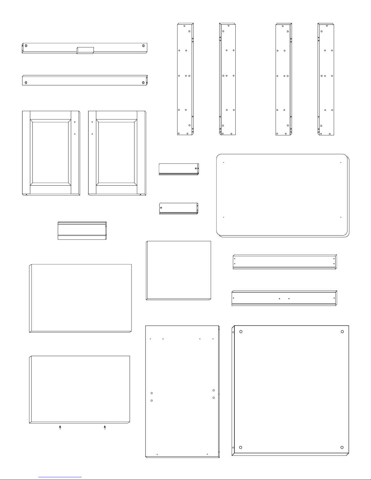
PARTS 64024
P/N: B-27/2/64024/TF
Top Front Brace (1)
Inside View
P/N: B-27/2/64024/BF
Bottom Front Brace (1)
Inside
Inside View
Inside View
P/N: DOOR-64024L
Left Door (1)
P/N: SIDE SHELF-64024
Side Shelf (8)
INSIDE
P/N: DOOR-64024R
Right Door (1)
P/N: L-31/5/RF/64024 P/N: L-31/5/LF/64024
Front Legs (2)
P/N: DS-18R 64024
Right
Drawer Side (1)
P/N: DS-18L 64024
Left
Drawer Side (1)
P/N: DBOT 64024
Drawer Bottom (1)
P/N: L-31/5/LB/64024 P/N: L-31/5/RB/64024
Back Legs (2)
P/N: TT 64024
Table Top (1)
P/N: DBK 64024
Drawer Back (1)
P/N: DF 64024
Drawer Front (1)
P/N: 64024/BOT
Bottom Shelf (1)
EDGE BANDING
P/N: 64024/MID
Middle Shelf (1)
Inside View
P/N: SP 64024
Side Panel (2)
Inside View
P/N: BP 64024
Back Panel (1)
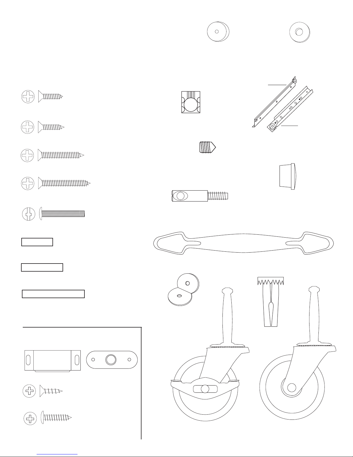
Hardware 64024
IMPORTANT NOTE ON SCREWS: Separate screws
into piles with a note on use as some are very similar.
DO NOT use the larger diameter 5/8” #8 screws to
attach the drawer glides. Screws for the glides have
flat heads & are much smaller in diameter. Double Check!!
(used on drawer glides packed separately)
5/8” Phillips Flat Head #6 Screw (4)
(used to attach
butterfly bracket)
Bastion Barrel Nut (10)
5/8” Phillips Flat Head #8 Screw (8)
(used to attach cabinet
drawer glides)
1” Phillips Flat Head #6 Screw (4)
Bastion Set Screw (10)
1 1/2” Phillips Flat Head #8 Screw (16)
(used on door/
drawer handles)
1” Truss Head Machine Screw (6)
P/N: SPACER
Plastic Spacer (4)
(Goes between cabinet
drawer glide & side panel)
P/N: B-NUT
P/N: SET SCREW
P/N: B-POST
Bastion Post (10)
3/16” Flat Washer (2)
Drawer
Cabinet
Drawer Glide (1 Set )
5/8” Wooden Disk (12)
(Packed with Hardware)
(Brace pins)
3/4” Long 3/16” DIA. Steel Pin (4)
(Shelf pins)
1” Long 3/16” DIA. Steel Pin (40)
(Door pins)
1 1/2” Long 3/16” DIA. Steel Pin (4)
Magnet Pack
Magnet (2)
1/2” Phillips Flat Head #4 Screw (2)
Magnet Plate (2)
(Used on Magnet Plate)
P/N: HANDLE 64024
Nickel Handle (3)
Butterfly
Brackets (4)
Caster Socket (4)
(Used on Magnet)
5/8” Pan Head Screw (4)
P/N: WHEEL 2L (LOCKING)
Locking Wheel Casters (2)
P/N: WHEEL 2 (NON-LOCKING)
Wheel Casters (2)
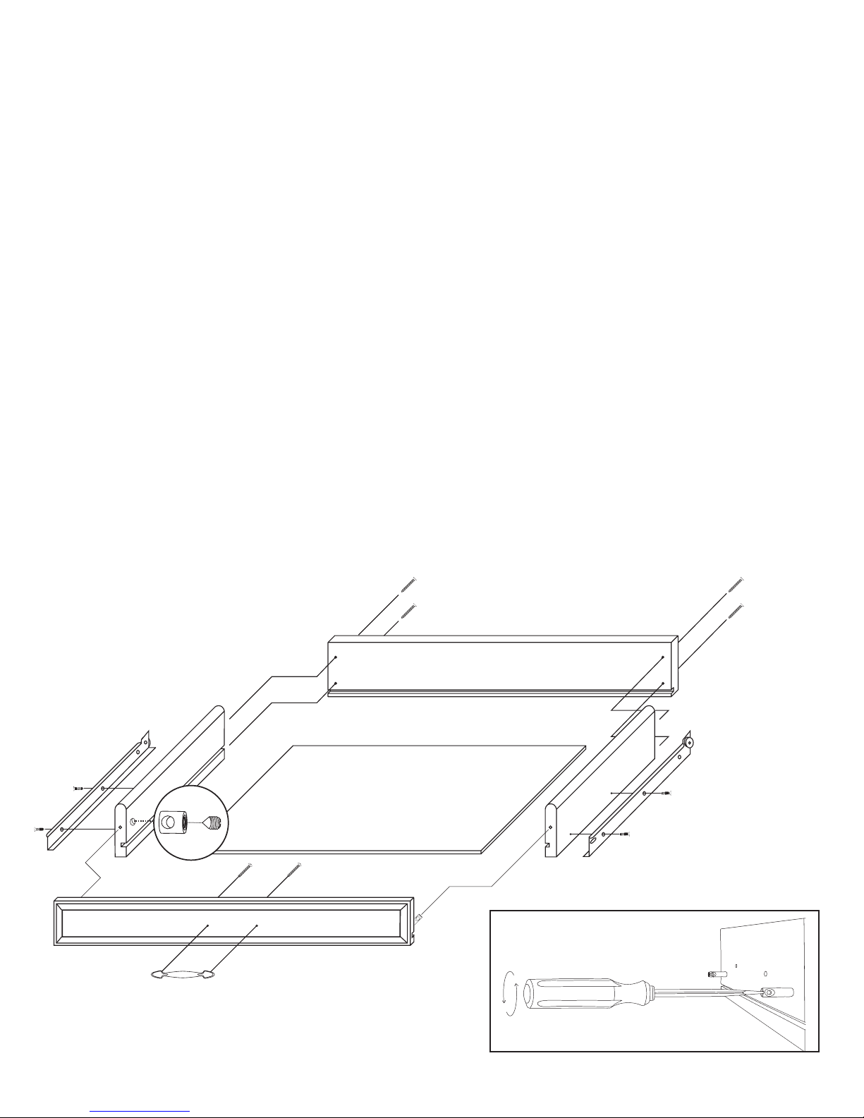
STEP 1
Assemble Drawer
A. Attach the drawer back to the drawer sides with four 1 1/2” #8 screws. There are left and right sides.
Make sure the slots that run the length of the sides are aligned with the slot in the drawer back to accept
the drawer bottom.
B. Slide in drawer bottom, best side up to inside of drawer.
C. Take 2 bastion posts, align the threaded end of the posts with the post holes located near the ends
of the inside of the drawer front. Tighten posts down until the solid shaft of the post hits the wood. Back
post out about 1/2 turn until the hole/screwdriver slot in the end of the post is parallel and in direct line
with the long edges of the Drawer Front. Dip threads in cooking oil to east turning.
D. Insert the barrel nuts into the nut access holes on the inside of the drawer side with the threaded
end of the nut facing out. Take the drawer front and carefully insert the posts into the ends of the brace
sides, through the sides of the nut until seated. Push nut snug up against the wood in the nut access
hole toward the inside drawer front. Hole should be slightly off-center toward the drawer front. Insert the
set screw and tighten down with a Phillips screwdriver. See illustration. The ends of the sides should
be tight against the inside drawer front. See Bastion video on our website www.catskillcraftsmen.com
E. Attach the drawer handle with the M 8-32 Pan Head Machine Screws.
F. Attach the drawer glides (left and right) to the Drawer Sides using two 5/8” #6 screws per side.
Wheels go toward drawer back and are up.
Illustration 1
STEP 2
INSIDE VIEW
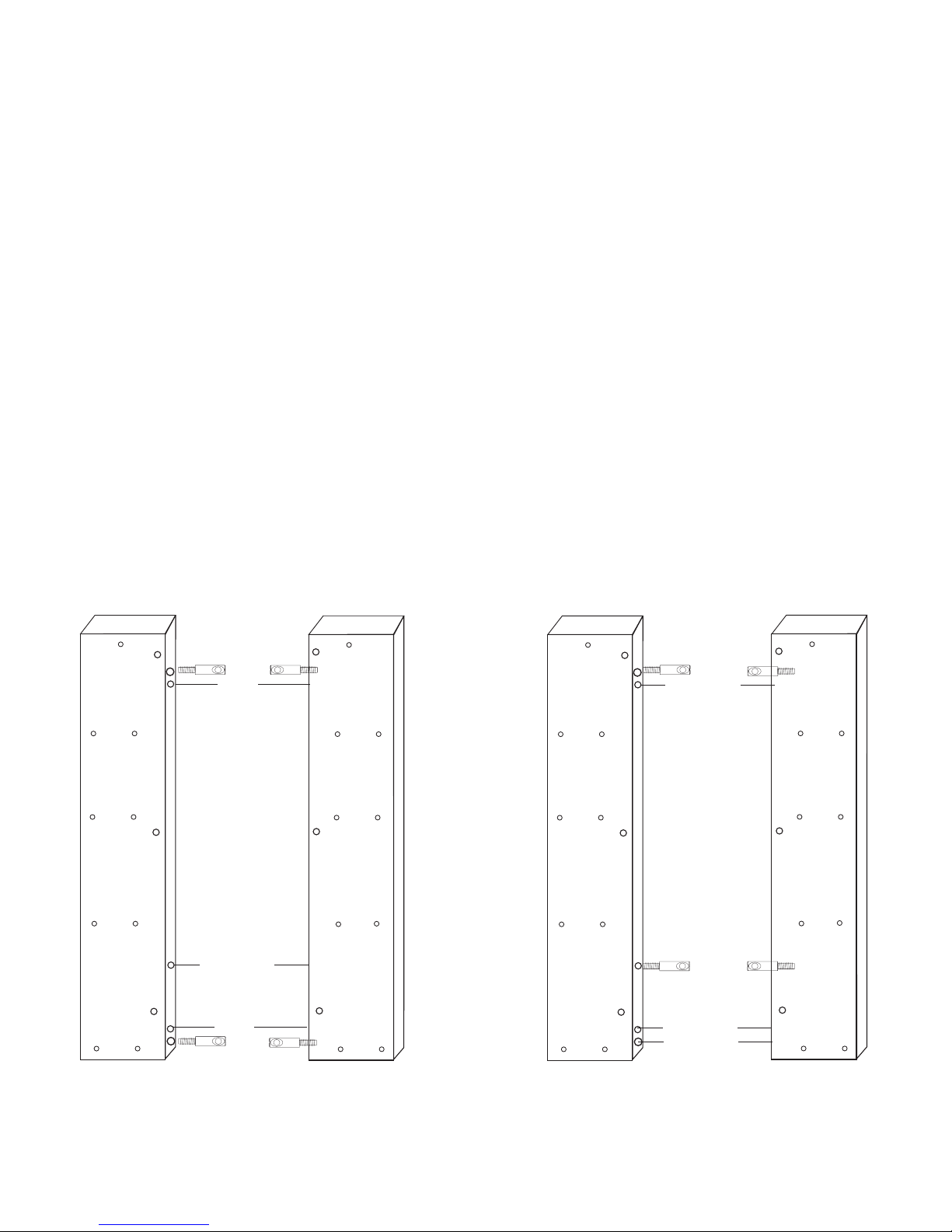
Attach Posts To Legs
A. There are 2 right legs and 2 left legs. Diagonal legs are the same (Example: Right Front /Left
Back). See Illustration 2 below which shows the legs paired (inside view) for the front and back panels
respectively. Notice that the position of the posts in the front legs differ from those in the back legs. This
difference will mean that there are some holes that are not used on all legs.
B. Take all 4 legs and lay out in pairs as in Illustration 2. Each pair of legs should be mirror images of
each other! Make sure the bottoms of the legs (hole in each of legs for caster is bottom) are down as
they are in the illustration.
C. On the Front Legs, posts will go into holes #1 and #5 counting down from the top. On the Back Legs,
posts will go into holes #1 and #3. On the Front Legs, hole #3 is not used. On the Back Legs, holes #4
and #5 are not used.
D. To seat posts, tap the slotted end of posts with hammer until threads just enter holes; then tighten
down (see “Tips On How The Bastion System Works” for alternative methods) until the solid shaft of
the post hits the wood, then back at least 1 full turn so that the hole in the post is perpendicular to the
length of leg/wood grain. Screw posts into all 4 legs. Double check with Illustration 2.
(B)
(B)
(B)
(B)
(A)
(A)
(A)
FRONT LEGS
TOP
Posts
Pins
NOT USED
Pins
Posts
(A)
(B)
(B)
(A)
(B)
(A)
(B)
(A) Thru holes
used to attach
Side Panels
(B) Pin holes
for pins that
support Side
Shelves Sets
of 2
(B)
(B)
(B)
(B)
(A)
(A)
(A)
BACK LEGS
TOP
Posts
NOT USED
Posts
NOT USED
NOT USED
(A)
(B)
(B)
(A)
(B)
(A)
(B)
RIGHT
LEFT
Illustration 2
LEFT
RIGHT
Note: Only the post holes are used
on Back Legs.
 Loading...