

Page 1

Assembly Instructions
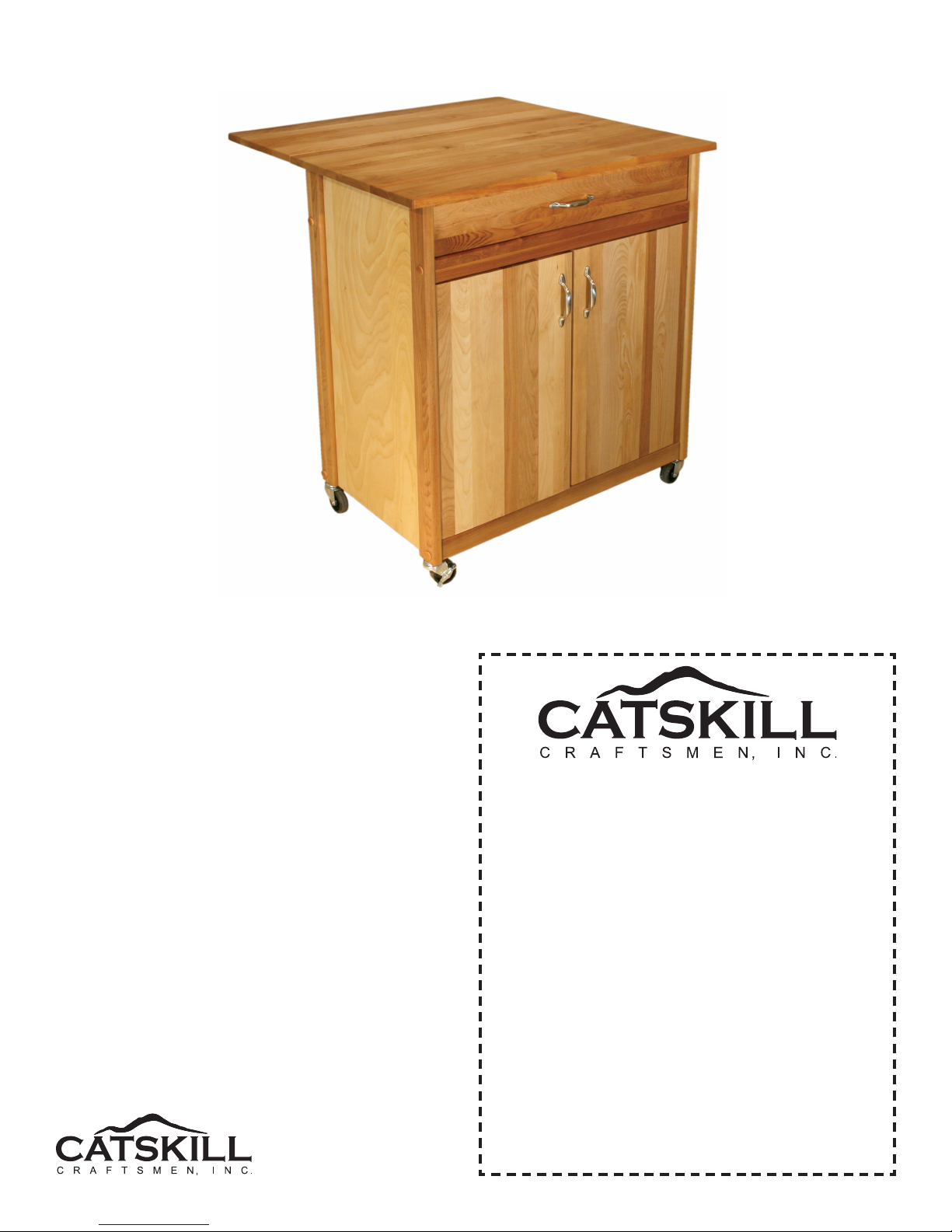
Model 51533
Mid-Sized Two Door Cart with Drop Leaf
GENERAL:
1. You have purchased model 51533.
2. Should you need assistance or need to replace a damaged or missing part simply give us a call M-F at
607-652-7321 from 7:30 am - 4:30 pm EST and we’ll send you the prepaid part via UPS usually that same day!
You may also email us [email protected].
3. Read the assembly instructions and the enclosed brochure before beginning assembly. Assembly is easy if
you read and follow the instructions step by step. See our website www.catskillcraftsmen.com for assembly tips
and videos.
4. The only tools needed are a hammer, a small and a medium Phillips head screwdriver and a medium at blade
screwdriver. A pencil is also needed. A power screwdriver will speed assembly but is not required. Tip: Place a
few drops of vegetable oil on the threads of wood screws before screwing them into the solid hardwood pieces.
5. Glides are sometimes pre-packed with screws - these are not used.
Page 2
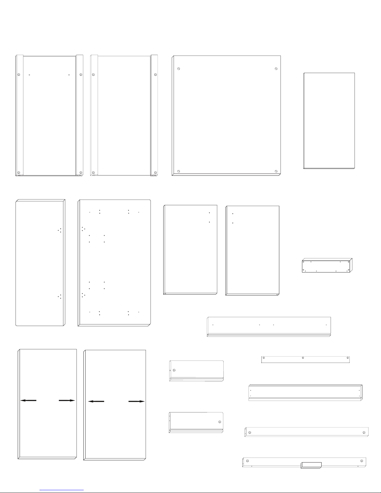
CABINET PARTS 51533
Handle Side Panel (1)
P/N:SP/HDL-51533
TOPTO TP OP
Plain Side Panel (1)
P/N:SP/PL-51533
Back Panel (1)
P/N:BP-51533
Drawer Bottom (1)
P/N:DBOT-51533
Drop Leaf (1)
P/N:DL-51533
EDGE BANDING
GOES OUT
13 3/8”
Table Top (1)
P/N:TT-51533
13 13/16”
Left Door (1)
P/N:DOR-51533/L
Right Door (1)
P/N:DOR-51533/R
Drawer Side Left (1)
P/N:DS-51533/L
Drawer Side Right (1)
P/N:DS-51533/R
Glide Support Sticks (2)
P/N: GLD SUP - 51533
Drawer Front (1)
P/N:DF-51533
Door Spacer (1)
P/N:DORS-51533
Drawer Back (1)
P/N:DBK-51533
Bottom Brace (1)
P/N:B-51533 BF
Middle Shelf (1)
P/N:MS-51533
Bottom Shelf (1)
P/N:BS-51533
Top Brace (1)
P/N:B-17 1/2-TF-51533
Page 3
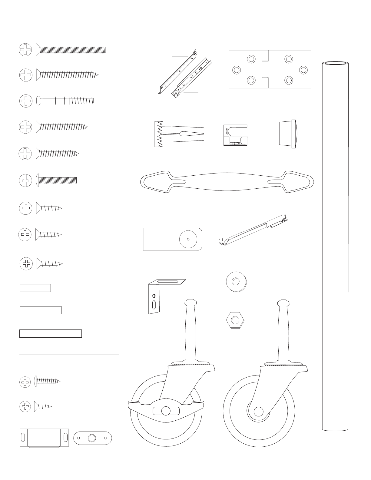
HARDWARE 51533
1 3/4” Phillips Flat Head Bolt (8)
(Used to attach
drawer back)
1 1/2” Phillips Flat Head #8 Screw (4)
(Used to attach
drawer front)
Cam Posts (2)
(Used to attach
glide supports)
1 1/4” Phillips Flat Head #8 Screw (8)
(Used to attach
towel bar)
1” Phillips Flat Head #8 Screw (2)
(Used to attach
door handles)
7/8” Truss Head Machine Screw (6)
(Used to attach cabinet
glides & “L” brackets)
5/8” Phillips Flat Head #7 Screw (12)
(Used on door spacer
& drop leaf hardware)
Drawer
Cabinet
Drawer Glide (1 Set )
Caster Socket (4)
Nickel Handle (3)
Cam (2)
Hinge (2)
5/8 Wooden Disk (8)
5/8” Phillips Flat Head #8 Screw (23)
(Used on Drawer Glides)
5/8” Phillips Flat Head #5 Screw (4)
(Brace Pin)
3/4” Long 3/16” DIA. Steel Pin (4)
(Shelf Pin)
1” Long 3/16” DIA. Steel Pin (8)
(Door Pin)
1 1/2” Long 3/16” DIA. Steel Pin (4)
MAGNET PACK
5/8” #6 Pan Head Screw (2)
1/2” Phillips Flat Head #4 Screw (1)
Towel Bar Post (2)
L-Bracket (4)
Drop Leaf Support (2)
3/16” Flat Washer (4)
10-24 Hex Nut (8)
Magnet (1)
Magnet Plate (1)
Locking Wheel Caster (2)
Non-Locking Wheel Caster (2)
Polished
Nickel Towel
Bar (1)
Page 4

5/8” #7 Screw
STEP 1
A. Decide which side to put the towel bar on. Attach a Glide Support Stick to the top of each Side
Panel using 1 1/4” #8 screws. The countersunk holes (reamed out) in the stick are positioned as
in illustration 1 so that the glide holes are toward the lower edge. Sticks should be ush with top of
panel.
B. Attach the cabinet glide of the Drawer Glide to the Glide Support Stick using 5/8” #7 at head
screws. Left glide to left Side Panel, right glide to right Side Panel. The glides look almost alike
however, the right glide (as you face the cart) has a rolled lip at the top of the glide that keeps the
drawer glide wheel in place. Line up the holes in the glides so that the end with the wheel comes
ush with the front edge of the Table Top Stick.
C. Attach the “L” brackets to the top of the glide supports using 5/8” #7 screws. Use the slot, the
side with the hole is used to attach the table top. The top of the “L” bracket should be even with the
top edge of the glide support stick.
Note: Glides are marked right/left with imprint behind wheel.
1 1/4” #8 Screw
TOP
TOP
5/8” #7 Screw
Page 5
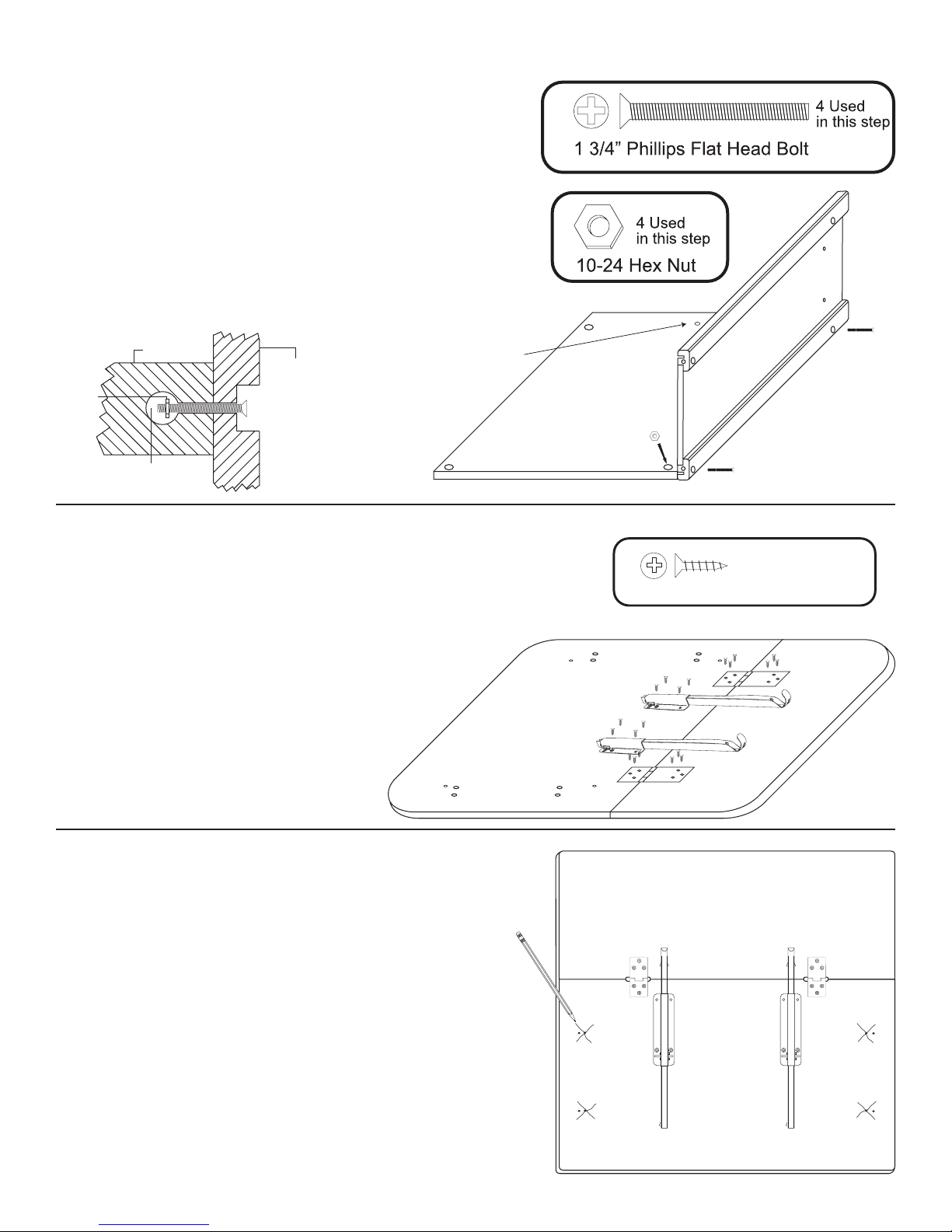
STEP 2
A. Lay back panel at on a smooth surface with holes up.
B. Attach both side panels (glide wheels go toward front
of cart) with 1 3/4” bolts and hex nuts. After inserting bolts
through the holes in the side panels, through the holes in
the long edges of the back panel, place a hex nut on the
tip of your nger, align nut with bolt and tighten.
C. Look ahead to step 5 which shows side panels
attached to back panel. Glide wheels toward the front.
Note: Make sure you position the side panels according
to drawer side left or right.
Not used
if present
Hex Nut
Inside Brace
Nut Access Hole
Side Panel Leg
Countersunk Hole in Leg
( disk goes in this hole to
hide bolt head! )
STEP 3
STEPS 3-13 WILL BE ACCOMPLISHED WITH THE UNIT TOP
UPSIDE DOWN (INVERTED), BUILDING UPWARD TOWARD
THE BOTTOM/CASTER END! BE CAREFUL AS PART
DESCRIPTIONS ARE BASED ON AN UPRIGHT,
COMPLETED UNIT!
Assemble top by placing the top and the drop leaf
upside down on a smooth at surface. Install
hinges using 5/8 #8 screws. The longer part
of the hinge goes on the drop leaf with the
short part on the cart top. Fasten the
drop leaf supports using 5/8 #8 screws.
20 Used in this step
5/8” Phillips Flat Head #8 Screw
STEP 4
Make a large X mark over each of the inside pilot holes in
the bottom. Make marks about 1 1/2” long. These marks
will help you align the cabinet with the inside pilot holes
in step 5.
This table top is used on two different models. The holes
on the outside, without markings in the illustration, are not
used.
Page 6
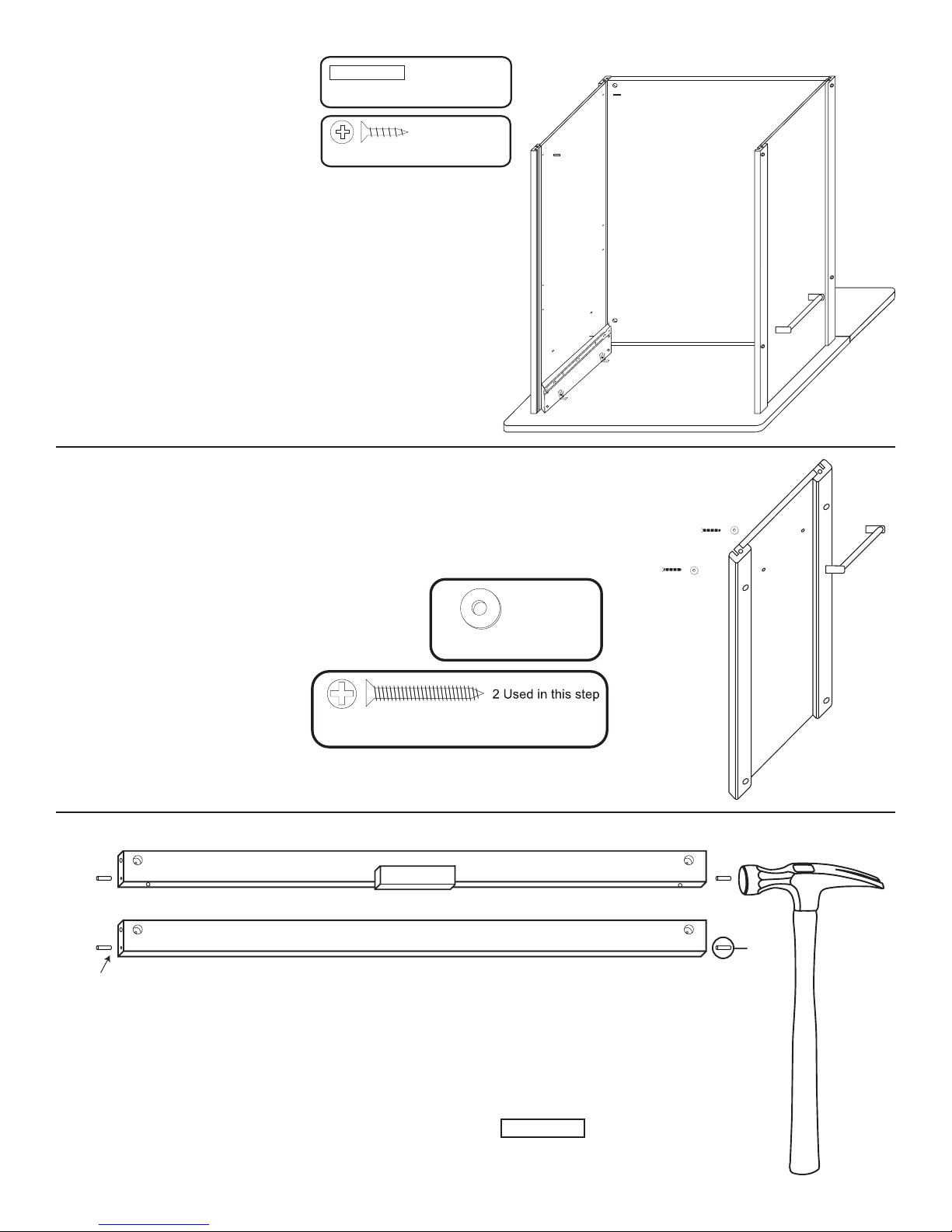
Top Front Brace
STEP 5
A. Turn the side/back
assembly upside down
(invert) on top of the
inverted table top.
1” Long 3/16” DIA. Steel Pin
5/8” Phillips Head #7 Screw
4 Used in this step
4 Used in this step
B. Using the X marks as a guide, insert the tips
of the 5/8 #7 screws into the pilot holes through
“L” bracket hole in the unit top and nger tighten.
When all 4 screws are properly aligned, tighten
down.
D. Tap two 1” pins into EACH side panel. These
pins will hold the bottom shelf as illustrated.
PIN
PIN
STEP 6
Attach Towel Bar to Side Panel
Attach the handle/towel bar to the side panel
with 1” #8 screws/washers from inside
the cabinet.
1” Phillips Flat Head #8 Screw
2 used
in this step
3/16” Flat Washer
Insert
STEP 7
Tap Pins Into Brace Ends
Take the 2 front braces and tap/insert one 3/4” steel pin
into each end of both braces until seated. About 3/8”
will stick out when seated. Pins may be loose.
3/4” Pin
Bottom Front Brace
4 used in this step
3/4” Long 3/16” DIA. Steel Pin
Page 7
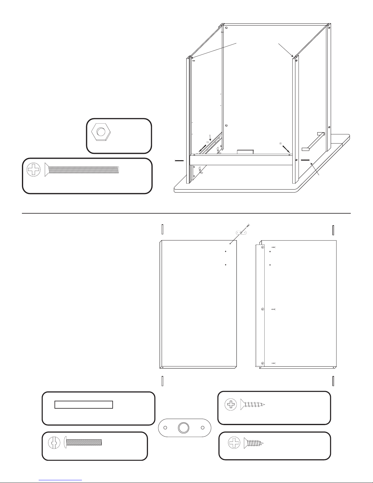
STEP 8
A. Take the top front brace (with magnet block) insert
pins into the brace ends. Slide the pins into the slits
on the inside of the front legs and slide down until
the brace aligns with the bolt holes.
B. Attach with 1 3/4” Phillips Flat Head Bolts
and Hex Nuts.
2 used
in this step
Hex Nut
2 used in
this step
1 3/4” Phillips Flat Head Bolt
Insert Brace Pins Here
and slide down into
correct position.
Glide Suport
Assembly
ILLUSTRATION 8
1 1/4” #8 Bolts
STEP 9
Door Prep
A. Insert/Tap ONE 1 1/2” pin into each
end of both doors. DON’T OVERDRIVE
PINS! Pins should stick up about 1/2”
when seated. Ok if pins are loose.
B. Attach the door spacer to the left door
with 5/8” #8 screws. The spacer has a
space at the top to allow magnet clear-
ance and is almost ush with the bottom
of the door.
C. Attach the magnet plate (may be stuck
to the magnet) with the small FLAT HEAD
screw to the top of the right door. Small
bumps on plate go against the wood.
D. Attach the door handles with 7/8” Truss
Head Machine Screw.
RIGHT DOOR
LEFT DOOR
4 used in
this step
1 1/2” Long 3/16” DIA. Steel Pin
4 used
in this step
7/8” Truss Head Machine Screw
Magnet Plate
3 used in this step
5/8” Phillips Flat Head #8 Screw
1 used in this step
1/2” Phillips Flat Head #4 Screw
Page 8
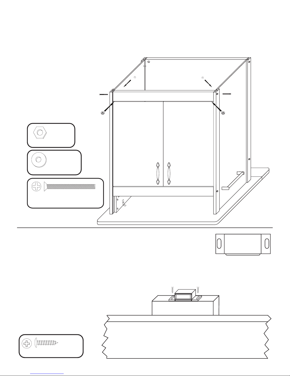
5/8” Pan Head Screw
2 Used
in this step
Magnet
5/8” Pan Head Screw
2 Used
in this step
STEP 10
Install Doors/Bottom Front Brace
A. Install doors by inserting pins in the door tops into the holes in the top front brace.
B. Place one washer on each of the door pins in the door bottoms.
C. Take the bottom front brace, align pins in
door bottoms with holes along top edge of
brace (Remember to put the washers
on the pins!!!) and secure with
1 3/4” bolts/hex nuts as before.
2 Used
in this step
10-24 Hex Nut
3/16” Flat Washer
1 3/4” Phillips Flat Head Bolt
2 Used in this step
STEP 11
Attach Magnet to Magnet Block
A. Stick magnet to magnet plate on right door.
B. With left door open, close the right door. The magnet should be positioned over the
wooden block on the bottom of the top front brace. Hold the magnet in place with your thumb, and
open the right door. The magnet will be in the correct position on the block. Mark with a pencil.
C. Secure magnet with the two pan head screws in the
magnet packet. Center screws in the slot in the
magnet. This will allow adjustments later,
if needed.
2 Used
in this step
Page 9
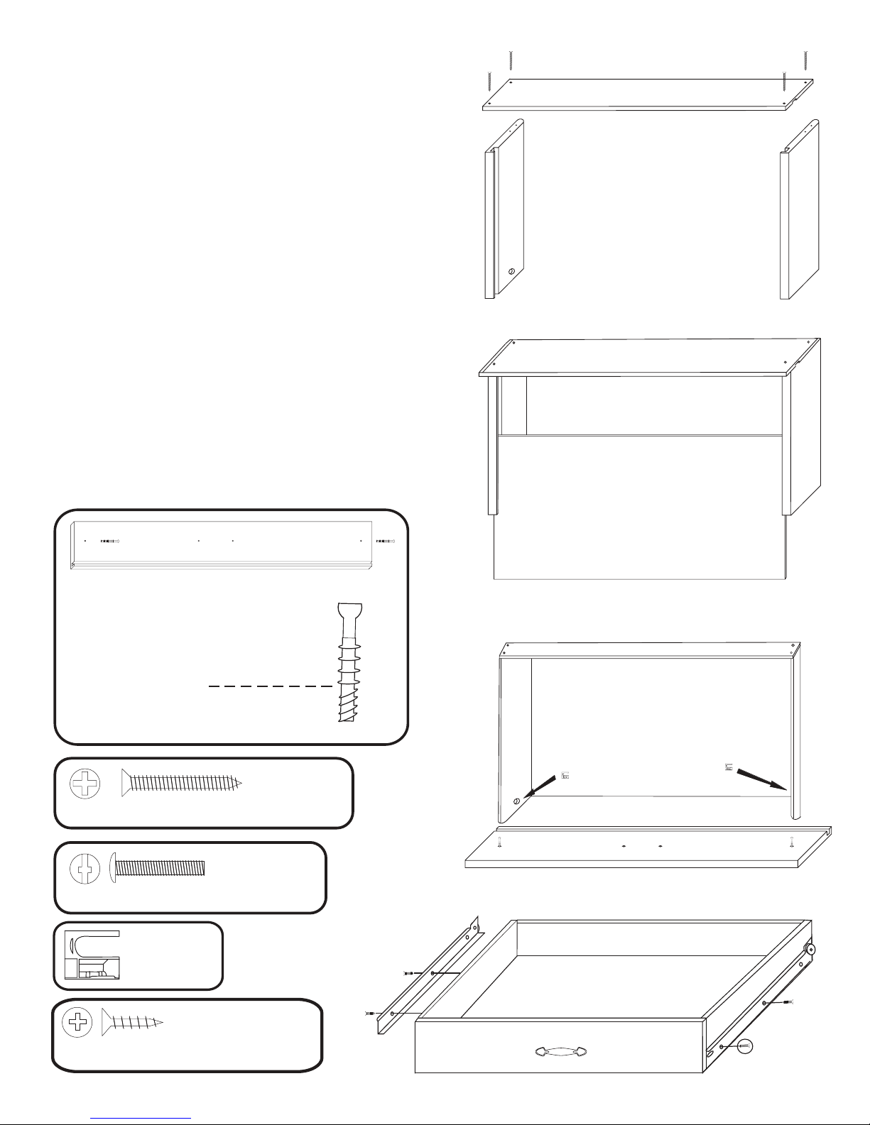
STEP 12
A. Attach the drawer back to the drawer side with four
1 1/4” #8 screws. Make sure parts are aligned as in
Illustration 12A.
B. Insert drawer bottom into the slots in the drawer sides,
best side to inside of the drawer. Slide down until seated
in the slot in the drawer back. See illustration 12B.
C. Screw the cam posts into the two outside holes on the
inside face of the drawer front until seated. Only 3/8” of
this post goes into the wood, leaving the 4 larger guide
rings/head exposed. See illustration 12C. Visit our website www.catskillcraftsmen.com for a video on cams.
D. Insert the posts into holes in the drawer side until
seated against the front ends of the drawer sides. Insert
cams so that slot in the cam ts over the posts and turn
with Phillips screwdriver until seated. Don’t over-torque!!
www.catskillcraftsmen.com
E. Attach drawer handle with the two 7/8” Truss Head
screws (no illustration)
F. Attach drawer glides to drawer sides using 5/8” #5
screws. See illustration 12E. Drawer glides are ush
with front of the drawer sides.
ILLUSTRATION 12A
ILLUSTRATION 12B
ILLUSTRATION 12C
Below line in wood
Cam Posts (2)
4 used
in this step
1 1/2” Phillips Flat Head #8 Screw
2 used
in this step
7/8” Truss Head Machine Screw
2 used
in this step
Cam
4 used
in this step
5/8” Phillips Flat Head #5 Screw
ILLUSTRATION 12D
ILLUSTRATION 12E
Page 10
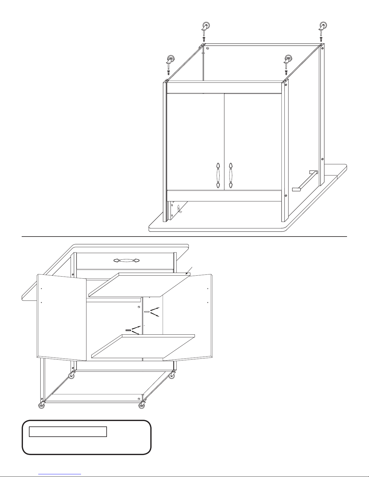
STEP 13
Install Casters
A. Insert and tap caster sockets with a
hammer until the teeth grab the wood.
DON’T POUND SOCKET FLAT OR
CASTER SHAFT WILL NOT ENTER.
B. Insert casters and seat by pushing
straight downward with the heel of your
hand, or tap into place with a hammer.
Don’t be afraid to give them a good
downward whack on the solid metal part
of the caster!
4 used in
this step
Edge
Banding
STEP 14
Install Shelves/Disks
A. Upright unit. Take bottom shelf (no
edge banding) and place it on the set
of back pins as shown. Close doors
and shelf will drop into place. DO NOT
FORCE!
B. Tap two 1” pins into each side panel
to hold middle shelf, making sure the
pins on both sides are in the same
relative position. To remove a pin, use
pliers or a claw hammer.
C. Place middle shelf, edge banding
out, on pins.
D. Insert drawer. If drawer hits the
bottom of the cart top or the top front
brace, tap the top front brace down,
then re-tighten screws and insert
wooden disks into sides.
E. Drop leaf supports should be
extended to initially insert drawer.
1” LONG 3/16” DIA. STEEL PIN
Page 11
For continued beauty and long life
of your Catskill Craftsmen cart, we
recommend Catskill Craftsmen’s
Butcher Block Oil. Our Butcher Block
Oil is available directly from Catskill
Craftsmen’s factory. For one eight
ounce (8 . oz.) bottle, which is
sufcient for two applications, simply
send $7.95 along with the completed
coupon to the address below. Visit
us online at www.catskillcraftsmen.
com to browse our assortment of
butcher block care products. Visa and
Mastercard are accepted online.
Catskill Craftsmen, Inc.
15 West End Ave.
Stamford, NY 12167-1296
BUTCHER BLOCK OIL COUPON
Please send me______ # of bottle(s) of the
Catskill Craftsmen Butcher Block Oil at $7.95
per bottle. My check or money order is
enclosed for a total of $_______________.
Item code: 51533
Name _______________________________
Address _____________________________
City ________________________________
State ________________ Zip ___________
Please make checks payable to Catskill Craftsmen Inc.
15 West End Ave., Stamford, NY 12167-1296
 Loading...