

Page 1
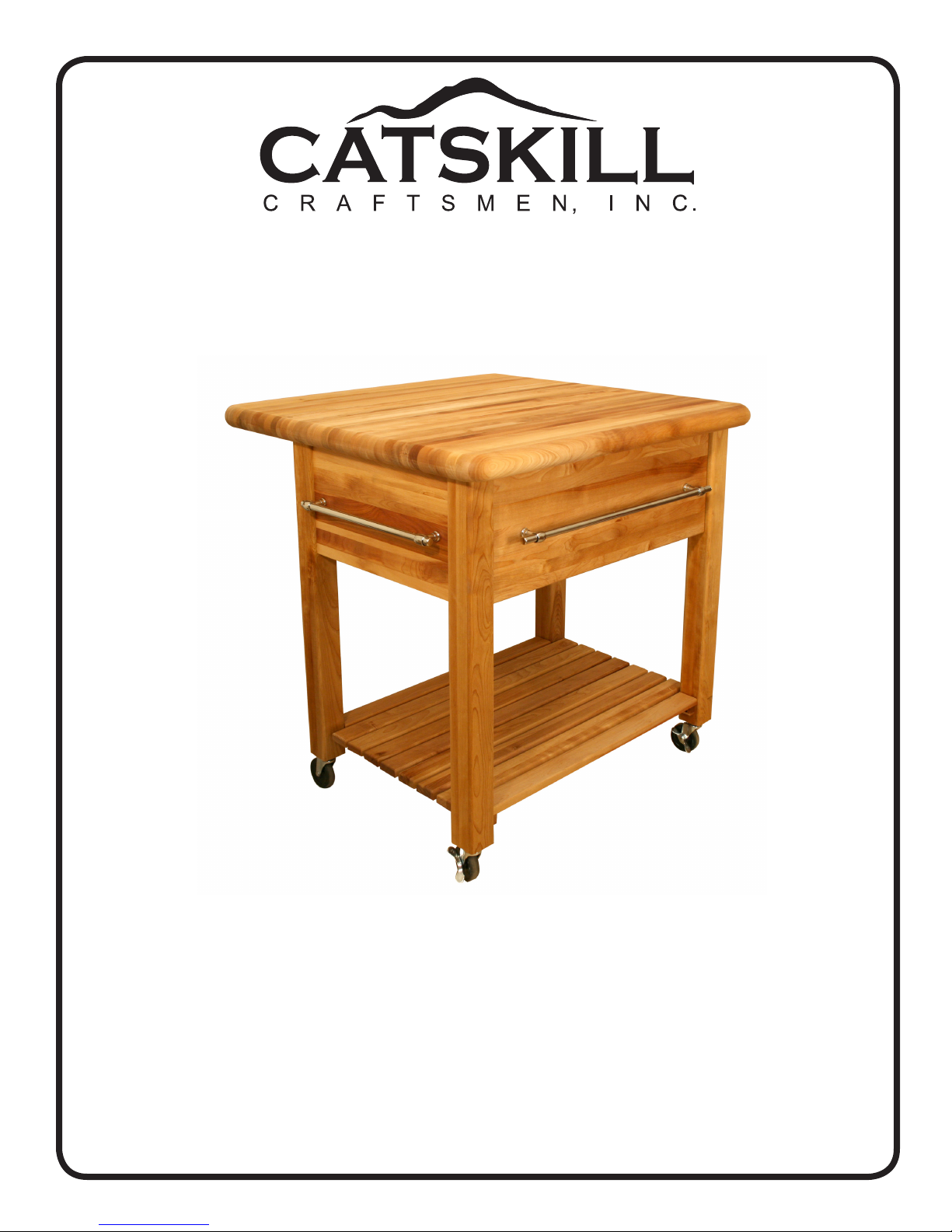
Assembly Instructions
Model 2005
The Grand WorkCenter with Drop Leaf
GENERAL:
1. Should you need assistance or need to replace a damaged or missing part simply give us a call M-F at
607-652-7321 from 7:30 am - 4:30 pm EST and we’ll send you the prepaid part via UPS usually that same
day! You may also email us [email protected].
2. Read the assembly instructions and the enclosed brochure before beginning assembly. Assembly is
easy if you read and follow the instructions step by step. See our website for assembly tips and videos.
3. Tools required: Phillips screwdrivers, medium and small; medium at blade screwdriver and a hammer.
4. This unit uses the Bastion System; a simple yet rugged compression fastening system. We have a
video online at www.catskillcraftsmen.com illustrating the proper installation of this system.
5. Directions (left/right, front/back) are given as facing the front of an assembled upright unit.
Page 2
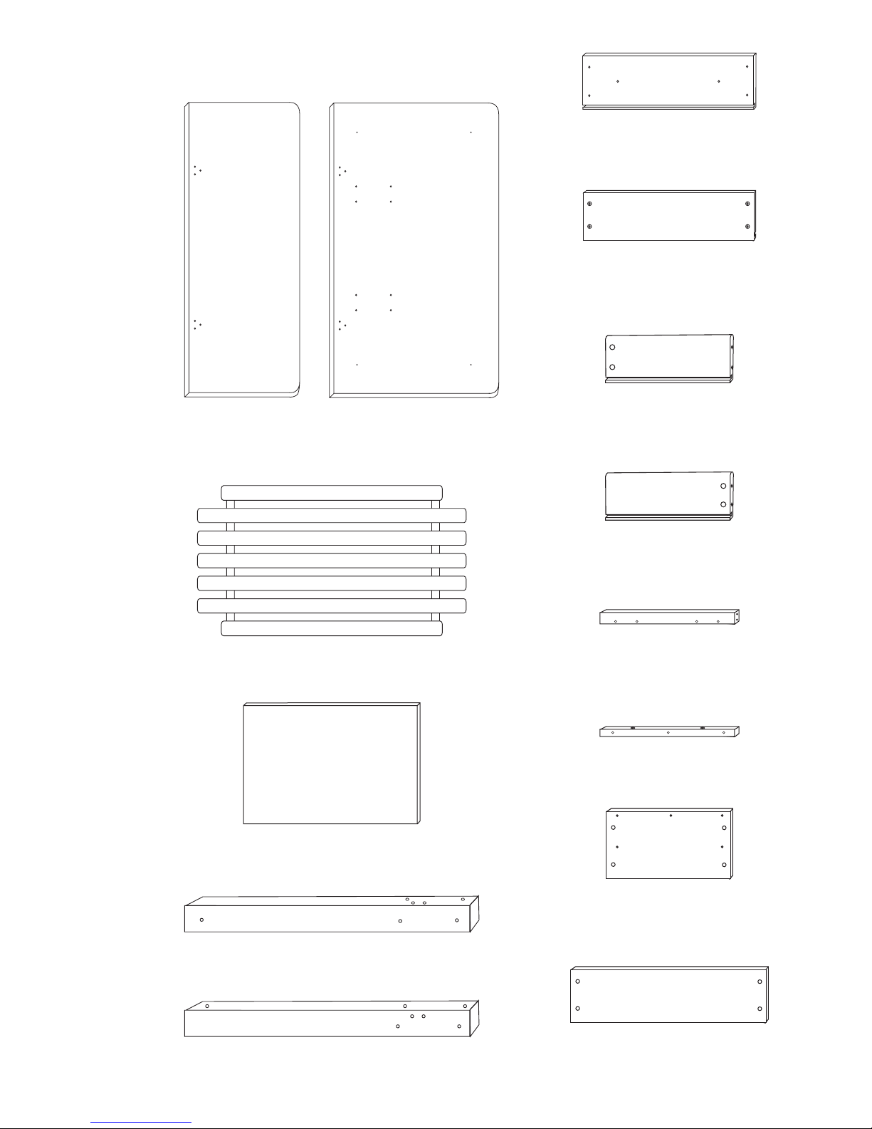
CABINET PARTS
Drop Leaf (1)
P/N DL-2005
Table Top (1)
P/N TT-2005
Drawer Front (1)
P/N DF-2005
28” x 10” x 3/4”
Drawer Back (1)
P/N DBK-2005
27 1/8” x 8” x 3/4”
Drawer Side Left (1)
P/N DS-2005L
18” x 8” x 3/4”
Drawer Side Right (1)
P/N DS-2005R
18” x 8” x 3/4”
Shelf (1)
P/N SS-2005
Drawer Bottom (1)
P/N DBOT-2005
Front Right/Back Left Legs (2)
P/N L-2005FR/BL
Front Left/Back Right Legs (2)
P/N L-2005FL/BR
Glide Support Braces (2)
P/N GS-2005
17” x 2” x 3/4”
Table Top Sticks (2)
15 3/4” x 3/4” x 3/4”
Top Side Braces (2)
P/N B-2005/TS
17” x 10” x 3/4”
Top Back Brace (1)
P/N B-2005/TB
28 1/8” x 8 3/4” x 3/4”
Page 3
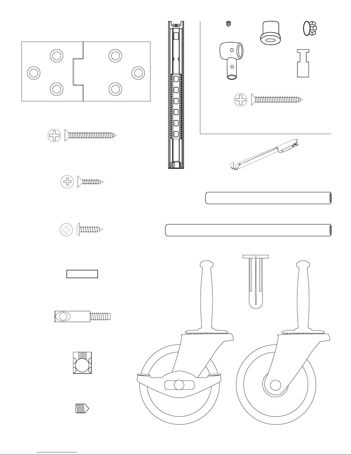
HARDWARE
Set Screw (12)
End Caps (6)
Standoffs (6)
Drop Leaf Hinges (3)
P/N HINGE-2005
1 1/4” Phillips Flat Head #8 Screw (18)
5/8” Phillips Flat Head #8 Screw (26)
7/16” Pan Head #6 Screw (8)
Full Ext Glide Set (1)
Pipe Holder (6)
1 1/4” Phillips Flat Head #8 Screw (6)
Towel Bar Post (6)
PREPACK
Drop Leaf Support (2)
16” Chrome Tube (2)
24” Chrome Tube (1)
3/4” Long 3/16” DIA. Steel Pin (8)
Bastion Post (16)
PN: BPost 2005
Bastion Barrel Nut (16)
PN: BNut 2005
Bastion Set Screw (16)
PN: BSS 2005
Wheel Insert-2005 (4)
3” Wheel Caster (2) 3” Locking Wheel Caster (2)
Page 4
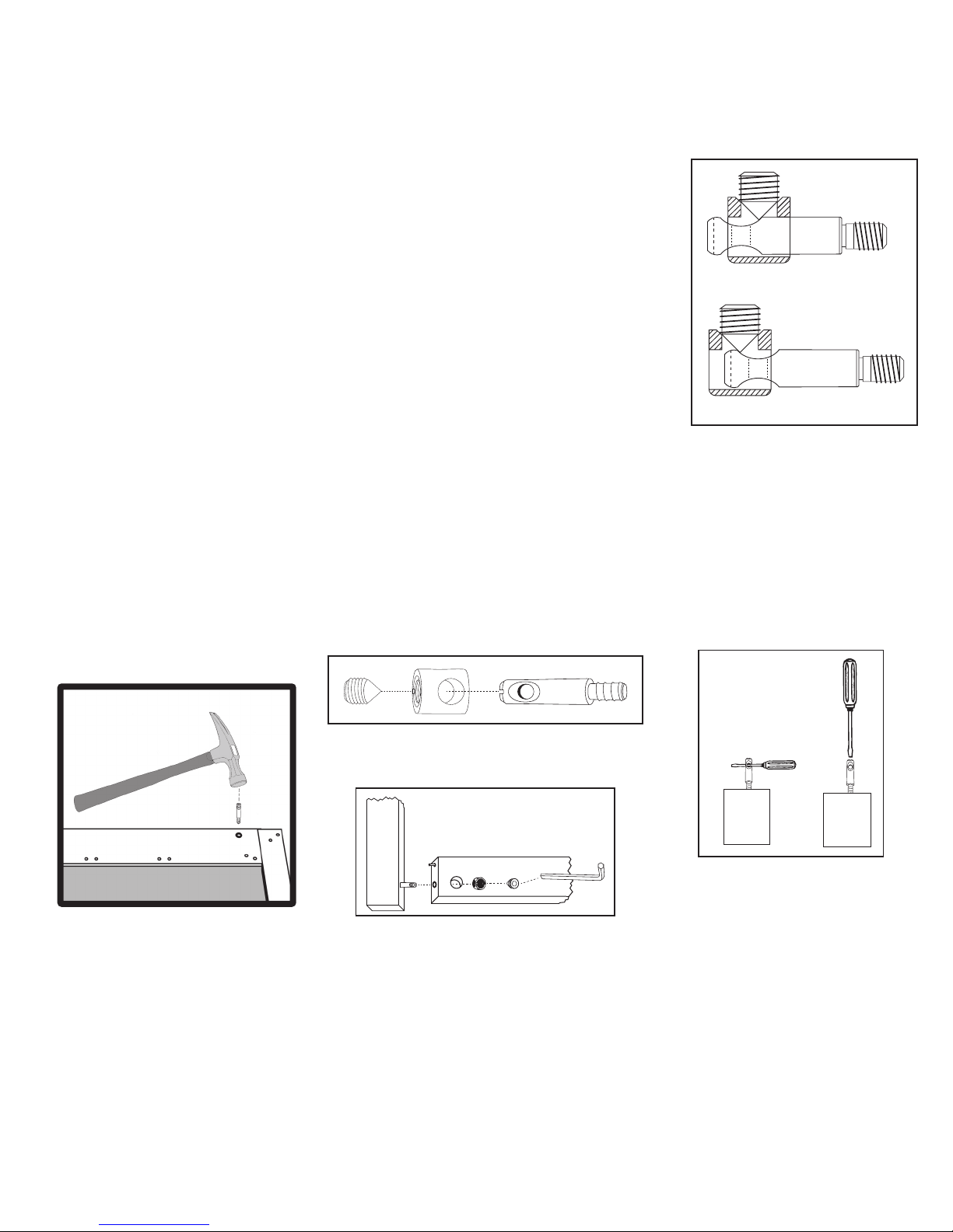
1. The Bastion fastening system consists of a steel post (threaded on one end with a
TIPS ON HOW THE BASTION FASTENING SYSTEM WORKS
hole through the shaft on the other end); a Barrel Nut (cylindrical barrel-shaped with
threaded open end & holes through the sides); and a Set Screw (Phillips slot on one end,
pointed on the other)
2. To attach Posts: A) Dip threads of Post in vegetable oil. B) Align threaded end of Post
with hole in wood, tap on slotted end with hard hammer until threads enter, then tighten
down using a flat head screw driver or the provided allen wrench (See the Illus. Bas. 3 for
alternate seating methods). DO NOT TRY TO HAMMER THE POST ALL THE WAY IN AS
IT WILL STRIP THE POST HOLE. C) When solid shaft of Post hits wood, back out
approximately ½ turn until the hole in the posts is properly aligned as per step by step
directions. For example: the holes in the posts on the inside of the drawer front will be
parallel with the long length of the drawer front when properly seated.
3. A) Place a Barrel Nut into the nut access hole, so that the threads in the nut face out.
The small notches on either side of the nut opening, indicate the location of the holes
through the sides of the nut. B) Insert the posts through the end of the braces (or drawer
sides); through the holes in the sides of the nut. When properly aligned, you will see the
hole in the post inside the barrel nut. Post hole should be slightly off-center toward the wood.
4. Insert the Set Screw into the threaded end of the nut and tighten down. The tip of the Set Screw will seek the center of
the hole in the Post as it is tightened down, forcing the Nut toward the main shaft of the Post. This is what tightens the
wooden parts together. Set screws should thread easily – DON’T CROSS THREAD! If Set Screw doesn’t thread easily,
check position of the hole in Post.
Illustration Bas. 1
Post needs to be screwed deeper.
WRONG!
RIGHT!
5. If the wooden parts are not tight against each other, the Post needs to be screwed a half turn at a time until wood joints
are tight.
Illustration Bas. 2
Step 1
Step 2
Illustration Bas. 3
ALTERNATIVE
METHODS FOR
SEATING POSTS
Allen Wrench Provided
See video on our website!
If you have any questions regarding assembly or missing or damaged
parts, call our customer support number:
607-652-7321 or 888-732-7321.
Page 5
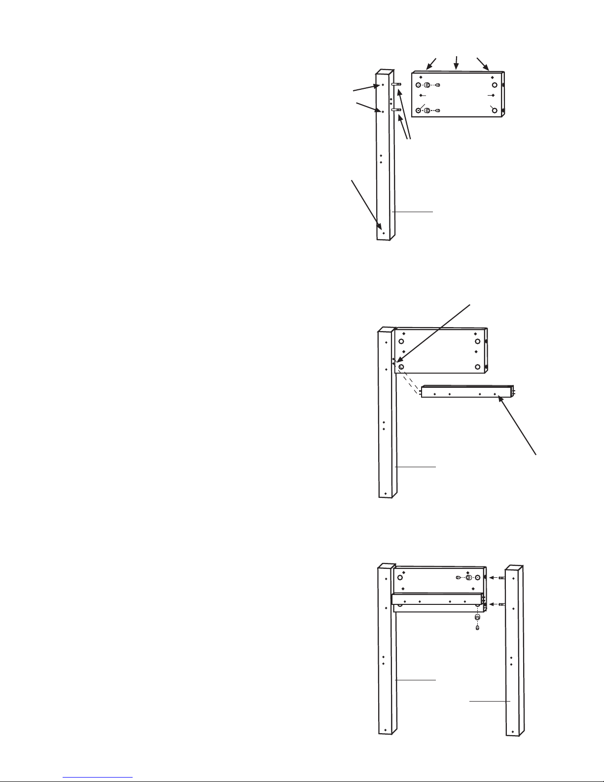
STEP 1
Table top L-Bracket holes
ASSEMBLE SIDE PANELS
A. Each side panel consists of two (2) legs, one
(1) top side brace and one (1) Glide Support
Brace. When assembled, diagonal legs will be
the same (i.e. Front Right/Back Left & Front
Left/Back Right). Side panels are identical when
assembled -- the Drawer Glides will determine
left and right sides.
B. Take each of the 4 legs and install two (2)
Bastion Posts per leg, on the side of the leg
which also has two (2) pin holes for the Glide
Support Sticks. Locate post holes. Tap Posts in
with hammer until threads engage wood; turn
Posts down until the solid shaft hits the wood
(All threads are into wood), then back Posts out
until the holes in the Posts are perpendicular to
the long length of the leg (about 1/2 turn).
C. Lay out Front Left leg and one (1) top side
brace as in Illustration 1A. Note the three pilot
holes for the table top sticks are along the top
inside of the top side brace.
not used
in front legs
bottom shelf hole
Towel bar holes
Nut access holes
TOP SIDE BRACE
Bastion Post
Left Front Leg
Illustration 1A
Glide Support Steel Pin Holes
D. Take the top side brace and drop two barrelshaped bronze bastion nuts into the nut access
holes as in illustration 1A. Threaded end-of the
nuts face out. Insert front left leg posts into the
holes in the ends of the brace, through the side
of the barrel nuts, until the holes in the posts
can be seen through the threaded end of the
nuts. Insert the Set Screws into the nuts and
tighten down. The tip of the set screw will seek
the center of the bastion post as it is tightened,
leaving a tight joint. If the joint is loose, check to
make sure the set screw is not cross-threaded
or that the post is out too far (not threaded
into leg deep enough.) See previous page for
Bastion illustrations for clarication of assembly.
E. Insert two 3/4” pins into each end of the glide
support brace. Position brace such that the pilot
holes for attaching the glide are towards the
bottom edge. Insert brace pins into the holes
on the inside of the left front leg as in illustration
1B (4 pilot holes out) with pilot holes off-center
toward the bottom of the leg.
GLIDE SUPPORT BRACE
Left Front Leg
Illustration 1B
Left Front Leg
Pilot holes go on
the bottom edge
F. Attach Back Left leg in same manner as in
illustration 1C.
G. Repeat for other side panel.
Left Back Leg
Illustration 1C
Page 6
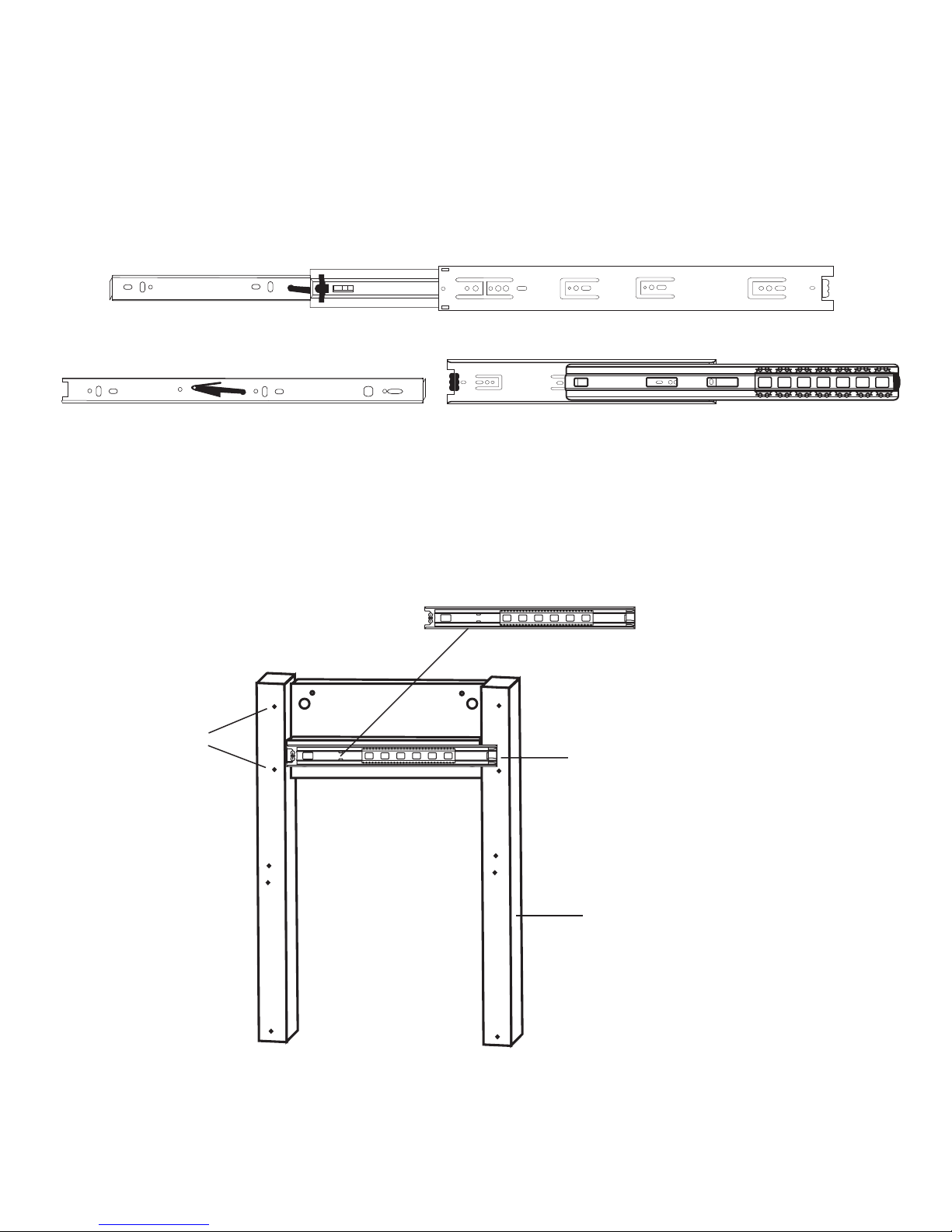
STEP 2
ATTACH DRAWER GLIDES TO GLIDE SUPPORT STICKS
A. Take the Drawer Glides, extend them to their fullest. See illustration 4. The Glide has 3 parts.
Remove the furthest extended part (1) (smallest) by pushing the black plastic lever down – then pull
part out, separating it. This part will attach to the Drawer Side later. Attach the largest parts (2&3) to
the Glide Support Stick using holes as illustrated. Attach with 1/2” #6 pan head screws. About 1 1/4”
of this glide will overlap the Front Leg. See illustration 2B.
B. Repeat with the other side.
(1)
Gets attached to the Drawer Side
(1)
Tab faces out
This side of Part (3) goes against the Glide Support Brace. Screw holes are blackened.
Bastion Post
Positions for Top
Back Brace
(2)
Illustration 2A
This shows back side of Glide. Part (1) is separated from Parts (2) & (3).
Gets attached to the Glide Support Brace
This end of the glide overlaps front leg 1 1/4”
& the bottom edge drops below the
(3)
This side goes against glide support brace
(2) & (3)
glide support brace
PREPARE SIDE ASSEMBLIES FOR BACK BRACES
The top back brace utilizes the bastion system for attachment. Place the bastion posts into their
positions on the back legs only of both side assemblies.
Right Front Leg
Illustration 2B
Page 7
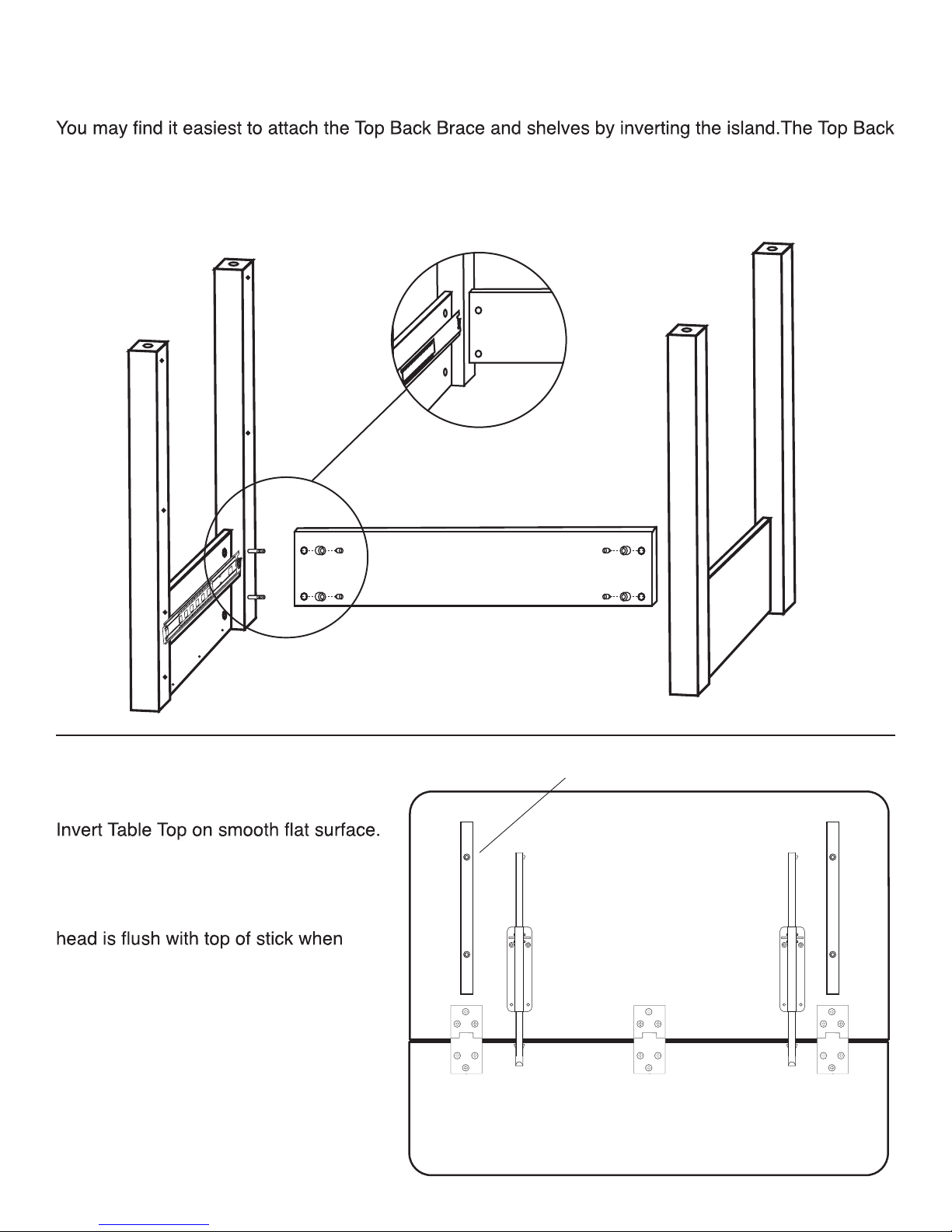
STEP 3
The 3 counter sunk holes on the
ATTACH THE BACK BRACE
Brace is located 1 1/4” down on the legs. This allows clearance for hinges and the drop leaf supports.
Attach the Top Back Brace to the left and right side panels with bastions.
Should be 1 1/4 in. space from
top of brace to top of cart.
Note: the access holes are closer to the top edge
of the brace when positioned correctly.
STEP 4
TABLE TOP PREPARATION
Attach the 2 Table Top Sticks to the
bottom of the table top with 1 1/4” #8
screws, 2 per stick countersunk holes
on top of the stick are up so that screw
tightened down. Attach the 3 hinges
with 5/8” #8 screws large part of hinges
go on Drop Leaf. Attach Drop Leaf
Supports with 5/8” #8 screws.
Top Edge
Table Top Sticks Face in.
Page 8
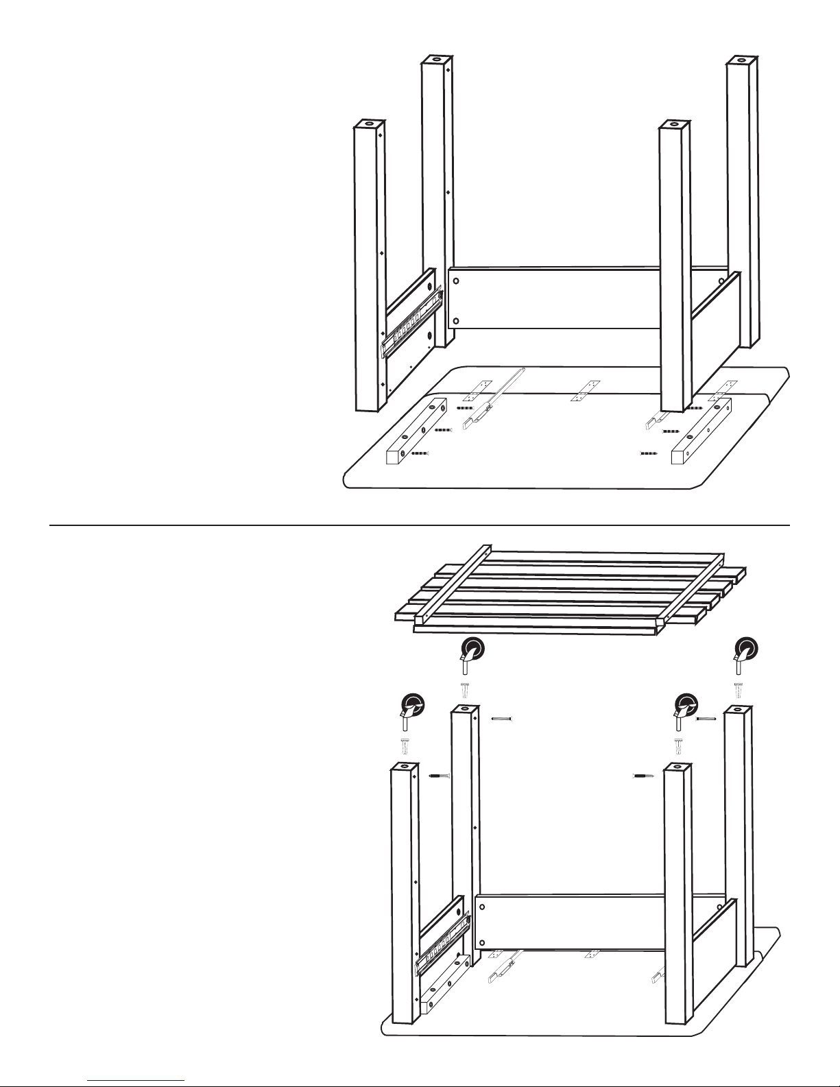
STEP 5
ATTACH LEGS TO TABLE TOP
With Top still inverted, secure top to
leg assembly with 1 1/4” #8 screws
through Table Top Sticks. Three
screws per stick.
STEP 6
ATTACH CASTERS &
BOTTOM SHELF
With unit still upside down, tap
caster sockets into holes in leg
ends until seated, then tap in
casters. Hit on metal part of caster
to seat. Locking casters usually go
on the front, non-locking casters
on the back. Use 1 1/4” #8 screws
to attach shelf to the inside of the
4 legs. Keep unit upside down for
step 7.
Page 9
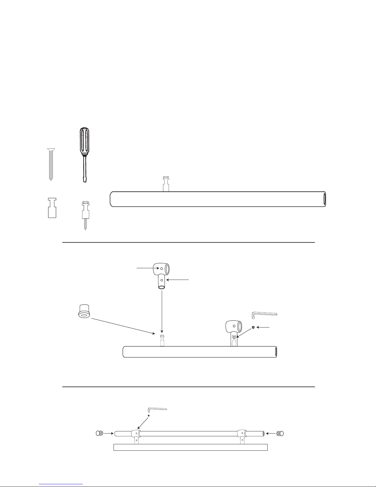
STEP 7
ATTACH TOWEL BARS
Note: Unit should still be inverted
See Illustrations. Screw brass towel bar posts into the top side braces and the drawer front using
1 1/4” #8 screws. Attach pipe holder by sliding supports over posts and secure with tiny set screws
using allen wrench provided. Slide towel bar through holes in supports and secure in place with
set screws. Bar should be equidistant on either side of the supports. Tap end caps into place. See
Illustration 7C.
Pipe Holder
Set Screw Hole
Standoff use optional.
If used, it must be placed
on Post prior to the
Pipe Holder!
Illustration 7A
BOTTOM VIEW
Set Screw Hole
Allen Wrench
Set Screw
Illustration 7B
Illustration 7C
Page 10
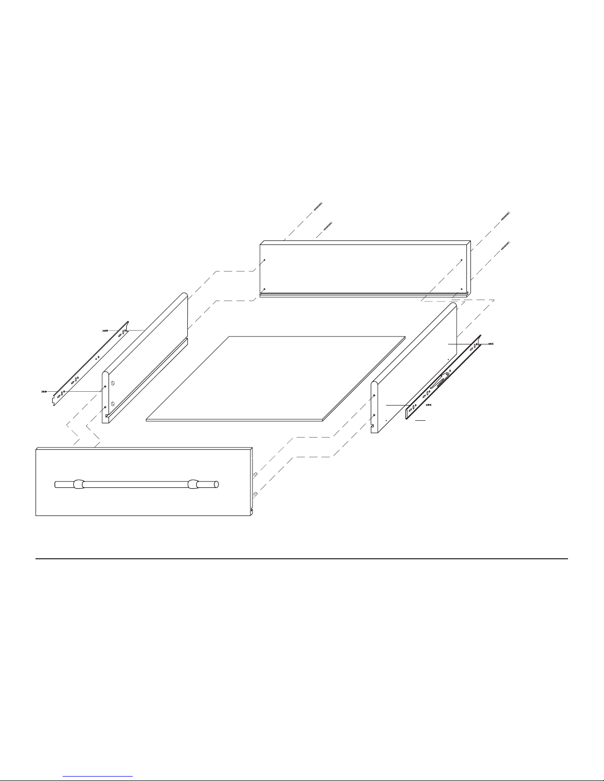
STEP 8
ASSEMBLE DRAWER
A. Attach the drawer back to the drawer sides with 1 1/4” #8 screws. Slide in drawer bottom, best side
up. Attach front using the Bastion System. Holes in the posts will be parallel to the long edge of the
drawer front. See illustration.
B. Attach the drawer glide to the drawer sides with 1/2” #6 screws in the places indicated in the
illustration. Black plastic lever will face outward. Glide will be up against the back of the drawer front.
Holes along the
bottom edge of the
drawer sides are not
used in this model.
STEP 9
FINAL STEPS
After you have the drawer assembled simply upright the unit and attach the drawer to the cart by
sliding it into the Glide Rails. Drawer glides will lock into place.
Page 11
For continued beauty and long life of your
Catskill Craftsmen cart, we recommend
Catskill Craftsmen’s Butcher Block Oil.
Our Butcher Block Oil is available directly from Catskill Craftsmen’s factory. For
one eight ounce (8 . oz.) bottle, which
is sufcient for two applications, simply
send $
7.95 along with the completed
coupon to the address below. Visit us
online
at www.catskillcraftsmen.com to
browse our assortment of butcher block
care products. Visa and Mastercard are
accepted online .
Catskill Craftsmen, Inc.
15 West End Ave.
Stamford, NY 12167-1296
BUTCHER BLOCK OIL COUPON
Please send me______# of bottle(s) of the
Catskill Craftsmen Butcher Block Oil at $7.95
per bottle. My check or money order is
enclosed for a total of $____________.
Item code: 2005
Name
Address _____________________________
City ________________________________
State ___________ Zip ________________
Please make checks payable to Catskill Craftsmen
Inc. 15 West End Ave., Stamford, NY 12167-1296
_______________________________
 Loading...