

CATSKILL 1426 Assembly Instructions Manual
Assembly Instructions
Model 1426
The Americana WorkCenter
GENERAL:
1. You have purchased model 1426.
2. Should you need assistance or need to replace a damaged or missing part simply give us a call M-F at
607-652-7321 from 7:30 am - 4:30 pm EST and we’ll send you the prepaid part via UPS usually that same day!
You may also email us info@catskillcraftsmen.com.
3. These units are ready-to-assemble. Catskill uses positive fastening methods suh as wood screws and in some
places hidden Bastion Fasteners. You will need some standard houshold tools: hammer and screwdriver (power
screwdriver is recommended). Where possible, we have packaged some of the screws in seperate labeled packages. To keep hardware separate after packets are open, we suggest you place each type of screw into separate
containers. Note labels for screws and when they are to be used in assembly in the instructions.
4. Directions (left/right, front/back) are given as facing the front of an assembled upright unit.
5. A friend is reccommended to assist with assembly as this will ease the process. Some of the parts are large
and awkward to hold in place, and extra pair of hands are a huge help.

Parts List
Model 1426
(1) Top Back Brace
41” x 5-1/2” x 3/4”
Part #: TBB1426
(2) Front Center/Bottom Brace
41” x 2” x 3/4”
Part #: FCBB1426
(2) Back Center/Bottom Brace
41” x 2” x 3/4”
Part #: BCBB1426
(2) Right Front / Left Back Leg
30” x 2.5” x 2.5”
Part #: Leg-1426RFLB
(2) Bottom Drawer Fronts
19-1/4” x 11-7/16” x 3/4”
Part #:BDF1426
(2) Bottom Drawer Left Side
18” x 8” x 3/4”
Part #:BDLS1426
(2)Left Front / Right Back Leg
30” x 2.5” x 2.5”
Part #: Leg-1426LFRB
(2) Bottom Drawer Backs
18-1/2” x 8” x 3/4”
Part #:BDB1426
(2) Bottom Drawer Right Side
18” x 8” x 3/4”
Part #:BDRS1426
(2) Center Vertical Braces
11-9/16” x 2” x 3/4”
Part #: CVB1426
(2) Bottom Drawer Bottom
18-5/8” x 17-5/8” x 5.2mm
Part #: BDBottom1426
(3 sets) 20” Drawer Glide
Part #: GL-20-1426
(4) Back/Side Panels
19-7/16” x 11-7/8” x 5/32”
Part #: BSP1426
(1) Center Bottom Glide Support Stick
(4) Top/Bottom Side Glide Support Sticks
22-1/16” x 2” x 3/4”
Part #: CBGSS1426
(2) Top Side Braces
19-1/2” x 5-1/2” x 3/4”
Part #: TSB1426
19-7/16” x 2” x 3/4”
Part #: TBSGSS1426
(1) Top Drawer Left Side
17” x 4-1/4” x 3/4”
Part #:TDLS1426
(1) Top Drawer Front
40-13/16” x 5-3/8” x 3/4”
Part #:TDF1426
(1) Top Drawer Back
40” x 4-1/4”” x 3/4”
Part #: TDB1426
(1) Top Drawer Right Side
17” x 4-1/4” x 3/4”
Part #:TDRS1426
(4) 3” Locking Casters
Part #: WHEELS1426
(1) Top Drawer Bottom
39-1/8” x 17-5/8” x 5.2mm
Part #: TDBottom1426
(4) Caster Insert Sleeves
Part #: CIS1426
(4) Center/Bottom Side Braces
19-1/2” x 2” x 3/4”
Part #: CBSB1426
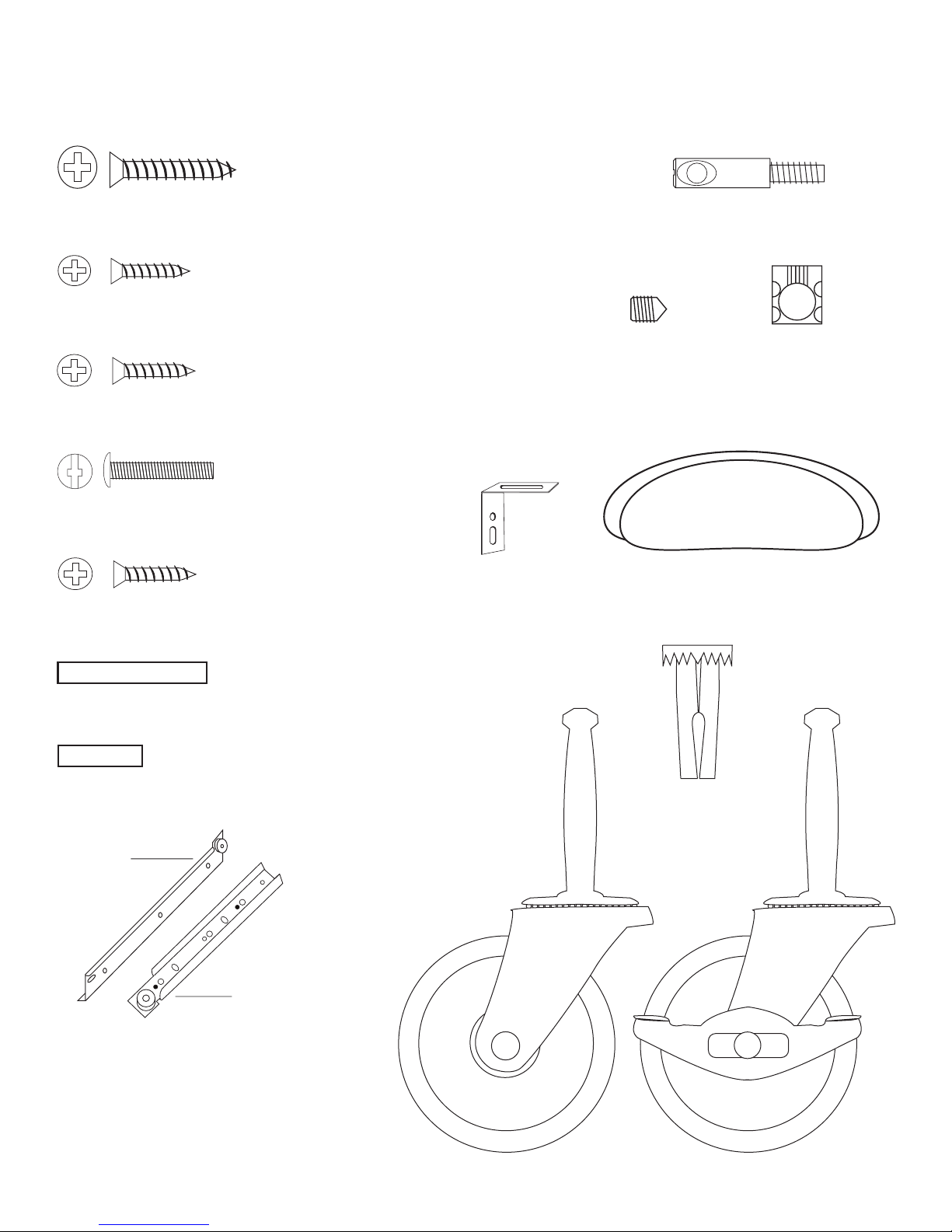
CABINET HARDWARE
1 1/4” Phillips Flat Head #8 Screw (12)
5/8” Phillips Flat Head #6 Screw (8)
5/8” Phillips Flat Head #5 Screw (12)
(Handle Screw)
3/4” Truss Head Machine Screw (8)
5/8” Phillips Flat Head #7 Screw (12)
“L” Bracket (4)
Bastion Post (34)
Bastion
Set Screw (34)
Handles (4)
Bastion
Barrel Nut (34)
1” Long 3/16” DIA. Steel Pin (6)
3/4” Long 3/16” DIA. Steel Pin (50)
Drawer
Cabinet
Drawer Glides (3 Sets)
The glides look almost alike
however, the right glide
(as you face the cart)
has a rolled lip at the top
of the glide that keeps the
drawer glide wheel in place.
Caster Socket (4)
Caster with Stops (2) Caster (2)
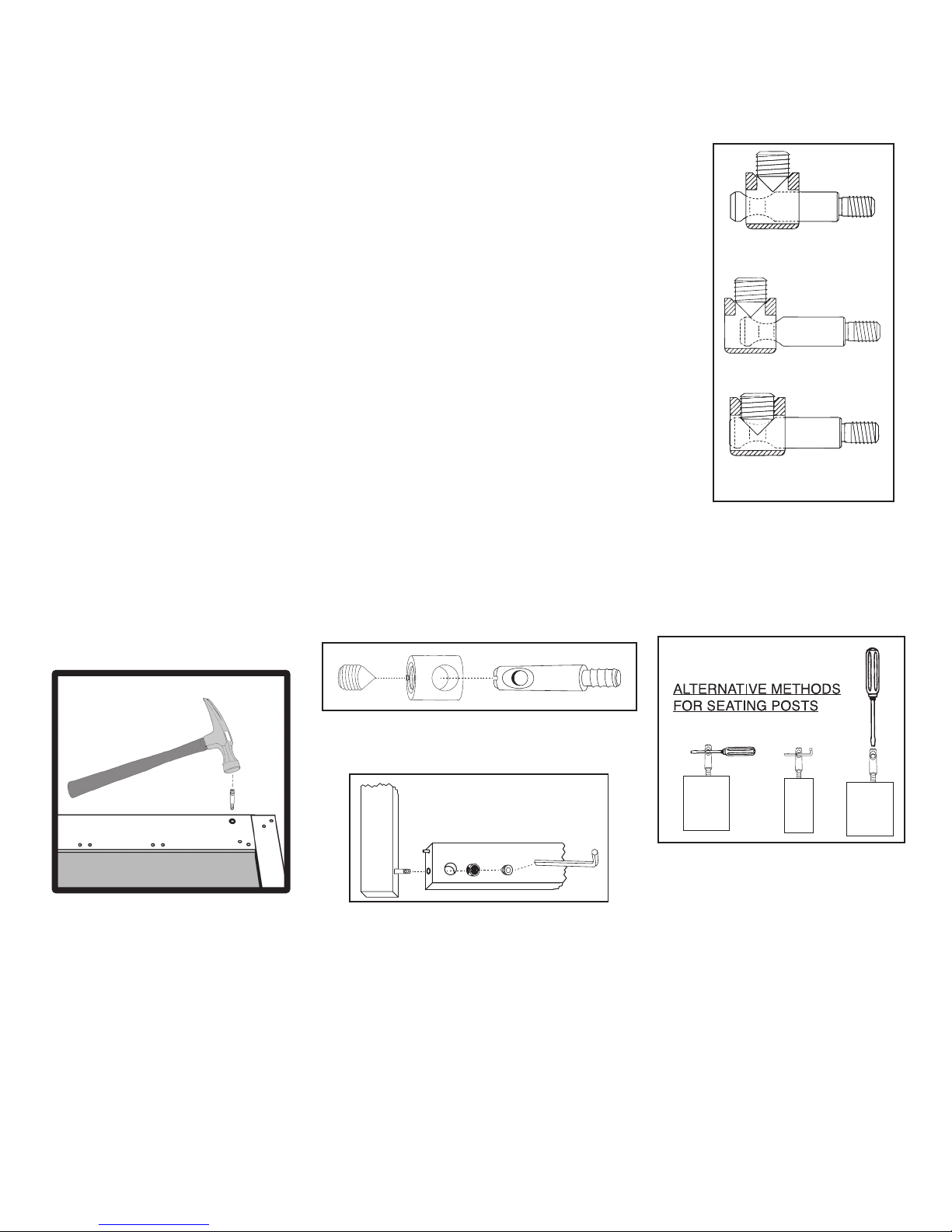
1. The Bastion fastening system consists of a steel post (threaded on one end with a hole
TIPS ON HOW THE BASTION FASTENING SYSTEM WORKS
through the shaft on the other end); a Barrel Nut (cylindrical barrel-shaped with threaded
open end & holes through the sides); and a Set Screw (Phillips slot on one end, pointed on
the other)
2. To attach Posts: A) Dip threads of Post in vegetable oil. B) Align threaded end of Post
with hole in wood, tap on slotted end with hard hammer until threads enter, then tighten
down using a flat head screw driver or the provided allen wrench (See the Illus. Bas. 3 for
alternate seating methods). DO NOT TRY TO HAMMER THE POST ALL THE WAY IN AS IT
WILL STRIP THE POST HOLE. C) When solid shaft of Post hits wood, back out
approximately ½ turn until the hole in the posts is properly aligned as per step by step
directions. For example: the holes in the posts on the inside of the drawer front will be
parallel with the long length of the drawer front when properly seated.
3. A) Place a Barrel Nut into the nut access hole, so that the threads in the nut face out.
The small notches on either side of the nut opening, indicate the location of the holes
through the sides of the nut. B) Insert the posts through the end of the braces (or drawer
sides); through the holes in the sides of the nut. When properly aligned, you will see the hole
in the post inside the barrel nut. Post hole should be slightly off-center toward the wood.
Illustration Bas. 1
WRONG!
Post needs to be screwed deeper.
WRONG!
Post needs to be backed out.
4. Insert the Set Screw into the threaded end of the nut and tighten down. The tip of the Set
Screw will seek the center of the hole in the Post as it is tightened down, forcing the Nut
toward the main shaft of the Post. This is what tightens the wooden parts together. Set
screws should thread easily – DON’T CROSS THREAD! If Set Screw doesn’t thread easily,
check position of the hole in Post.
5. If the wooden parts are not tight against each other, the Post needs to be screwed a half
turn at a time until wood joints are tight.
Illustration Bas. 2
Step 1
Step 2
Illustration Bas. 3
Set screw secures post properly.
CORRECT!
If you have any questions regarding assembly or missing or damage
parts, call our customer support number:
607-652-7321 or 888-732-7321.
Customer Support Hours are 8am-5pm Mon. - Fri. Eastern Time zone.
Allen Wrench Provided
See video on our website!
 Loading...