

Catrax Plus Product Manual
www.TURNSTILES.us
PRODUCT MANUAL
www.TURNSTILES.us * 8641 S. Warhawk Rd. * Conifer, CO 80433
Tel: 303 670 1099 ext 11 * Fax: 303 679 8949 * email: patrick.mcallister@TURNSTILES.us


Product Manual
INDEX
1 GUIDELINES ................................................................................................ 4
2 INTRODUCTION ........................................................................................... 4
3 CHARACTERISTICS ...................................................................................... 4
3.1 CATRAX Plus operating mechanisms ............................................................ 6
4 CATRAX PLUS ASSEMBLY / INSTALLATION ................................................. 6
4.1 Visual inspection ...................................................................................... 6
4.2 Preparing the installation site..................................................................... 7
4.3 Installing the column ................................................................................ 7
4.4 Mounting of arms and covers ..................................................................... 8
4.5 Access to the CATRAX Plus internal components after assembly ..................... 9
5 INSTALLATION/ASSEMBLY O F OPTIONAL PRODUCTS ................................. 9
5.1 Card collection kit with chute ..................................................................... 9
5.1.1 Connecting the card collection box to the control board ..................... 10
5.2 Pictogram kit ......................................................................................... 10
5.3 Counter................................................................................................. 11
5.4 Power supply ......................................................................................... 11
5.5 Control board ........................................................................................ 12
5.5.1 Inputs ......................................................................................... 13
5.5.2 Outputs ....................................................................................... 14
5.5.3 Control board configuration – Dip Switch 1....................................... 16
5.5.4 Configuration examples ................................................................. 16
5.6 No-break power unit ............................................................................... 16
5.6.1 Anti-panic device .......................................................................... 17
5.7 Display ................................................................................................. 17
5.7.1 Display configuration and operation via software .............................. 18
5.7.2 Adjusting the display manually ....................................................... 20
5.7.3 Connection table ........................................................................... 21
6 MAINTENANCE........................................................................................... 21
6.1 Preventive and corrective maintenance procedures..................................... 21
6.2 Troubleshooting ..................................................................................... 23
7 TECHNICAL CHARACTERISTIC S ................................................................. 23
8 WARRANTY AND TECHNICAL ASSISTANCE ................................................ 25
3

Product Manual
1 GUIDELINES
ı Carefully read the instructions contained in this manual before assembling and
installing the Catrax Plus turnstile. This will extend the life of the product and will
enable you to fully benefit from all its features.
ı This product was not designed for outdoor use in unprotected areas.
ı Retain this manual for future reference.
ı Digicon reserves the right to upgrade the characteristics of i ts products at any time
in order to incorporate technological advancements.
ı Digicon reserves the right to change the information contained in this manual
without notice.
ı Digicon does not provide any warranty related to the i nformation contained in this
manual. Digicon cannot be held responsible for any errors this manual may contain
or for any problems caused by its use.
ı The information contained in this manual is the exclusive property of Digicon and is
protected by copyright laws.
ı This manual may not be copied, photocopied or translated in its entirety or in part,
in any kind of medium, without Digicon’s written permission.
2INTRODUCTION
The CATRAX line of turnstiles was developed to be robust, reliable and esthetically
pleasing. Its rounded lines house a sturdy blocking mechanism designed for very low
maintenance.
CATRAX Plus serves all major access control technologies presently available, being
acclaimed as the best opti on in turnstiles in the market.
This manual presents a detailed description of CATRAX Plus operation and
components. To get to know other Digicon products, please visit our website at
www.digicon.com.br or www.catrax.com.br.
3 CHARACTERISTICS
The CATRAX Plus is a column-type mini turnstile with three bidirectional arms finished
with brushed stainless steel (AISI 304).
4
Product Manual
The column is available in two finishes: brushed stainless steel (AISI 304) or 1020
carbon steel with black or beige epoxy powder coating. It features fully rounded
corners and a smooth surface with no exposed screws, in addition to a reinforced
internal structure and plenty of space for practically any access control solution. It also
has room for a no-break power supply unit and a card coll ection box (not included).
In order to simplify maintenance and assembly, the column has an internal U-shaped
mounting rack with a standard set of holes for prompt mounting of electronic boards.
Additional holes can be drilled by the customer to accommodate specific needs.
For access to the mounting rack, use the keys that are provided with the turnstile.
Removal and insertion of the rack are extremely easy.
The upper column panels are manufactured in high-impact engineering plastic with
customizable stainless steel sheets. The plastic panels are available in green,
burgundy, or black. Special color orders are available upon consultation. The front
upper panel can have a slot for housing customer supplied magnetic and bar code
readers.
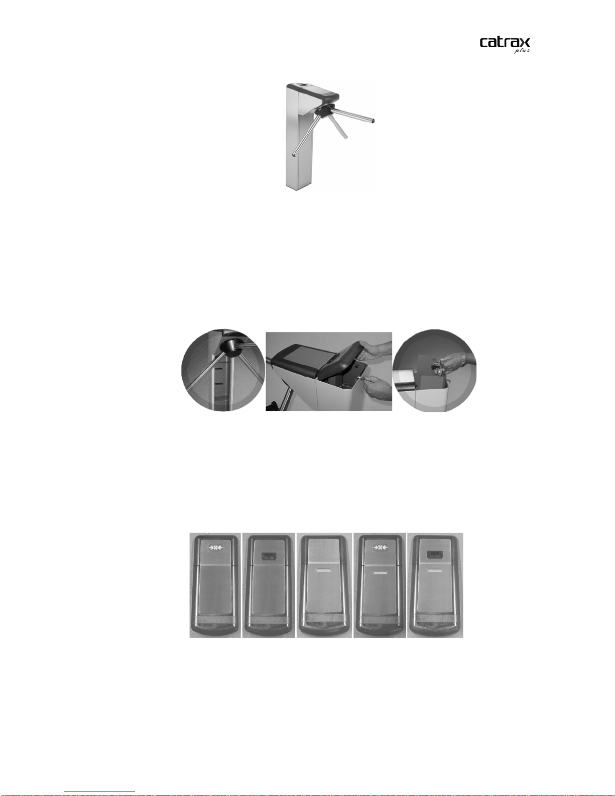
The upper cover stainless steel plates are designed for easy configuration and low-cost
customization. The plates can be easily punched to accommodate in tegrator options
such as displays, keyboards, biometric sensors, and pictogram LEDs/pictogram
indicators, as shown below:
Customization can be carried out with either a third party supplier or with Digicon
(subject to additional quotation).
The Catrax Plus is compatible with most technologies currently available. The following
optional items can also be ordered: card collection kit, pictogram kit, backlight display,
mechanical counter, power supply, control board, and no-break power supply unit.
5

Product Manual
These options will be described in greater detail in section 5 Installation/Assembly of
optional products.
NOTE
For detailed information on the dimensions of CATRAX Plus components, see
section 7 Technical Characteristics, page 23.
3.1 CATRAX PLUS OPERATING MECHANISMS
The CATRAX Plus features two operating mechanisms. The basic model (with no
control board) employs a bi directional rotation system with two 12 V electromagnets
that activate the locks and two optical sensors that provide the electromagnets wi th
informationonturncompletionanddirectionofturn.
An optional microprocessor-based control board is also available. In this case, an
“enable turn” signal is sent. If this signal is recognized, the arm will turn from left to
right or right to left depending on the signal received. Once half the turn (60 degrees)
is completed, a 400 ms return signal is emitted informing the direction of turn. After
this signal, the arm will not turn back.
Depending on the turnstile’s configuration and model, forcing the arm in the absence
of an “enable turn” signal will activate an electromagnet that locks the arm. In thi s
case, the equipment may also emit an audible alarm and/or display a red X on the
upper panel display (models with pictogram indicators). A return signal will then be
sent, indicating that the turnstile was forced and informing the direction of turn.
CAUTION
The specifications described above refer to optional items manufactured by
Digicon. However, products from other manufacturers may also be installed on
the CATRAX Plus basic model (including control boards).
4 CATRAX PLUS ASSEMBLY / INSTALLATION
4.1 V
Depending on the customer’s order the CATRAX Plus may include items that are not
factory-installed. It is very important to carry out a careful visual inspection of the
contents before beginning assembly and in stallation. Contents sh oul d be compared
with the checklist provided with the packag e.
ISUAL INSPECTION
CAUTION
In order to prevent the loss of access keys, bolts and spanners used to assemble
the CATRAX Plus, these items are taped to the box containing the arms. Before
disposing of any wrapping materials (plastic or cardboard), make sure that you
have identified all the items in the checklist.
6
Product Manual
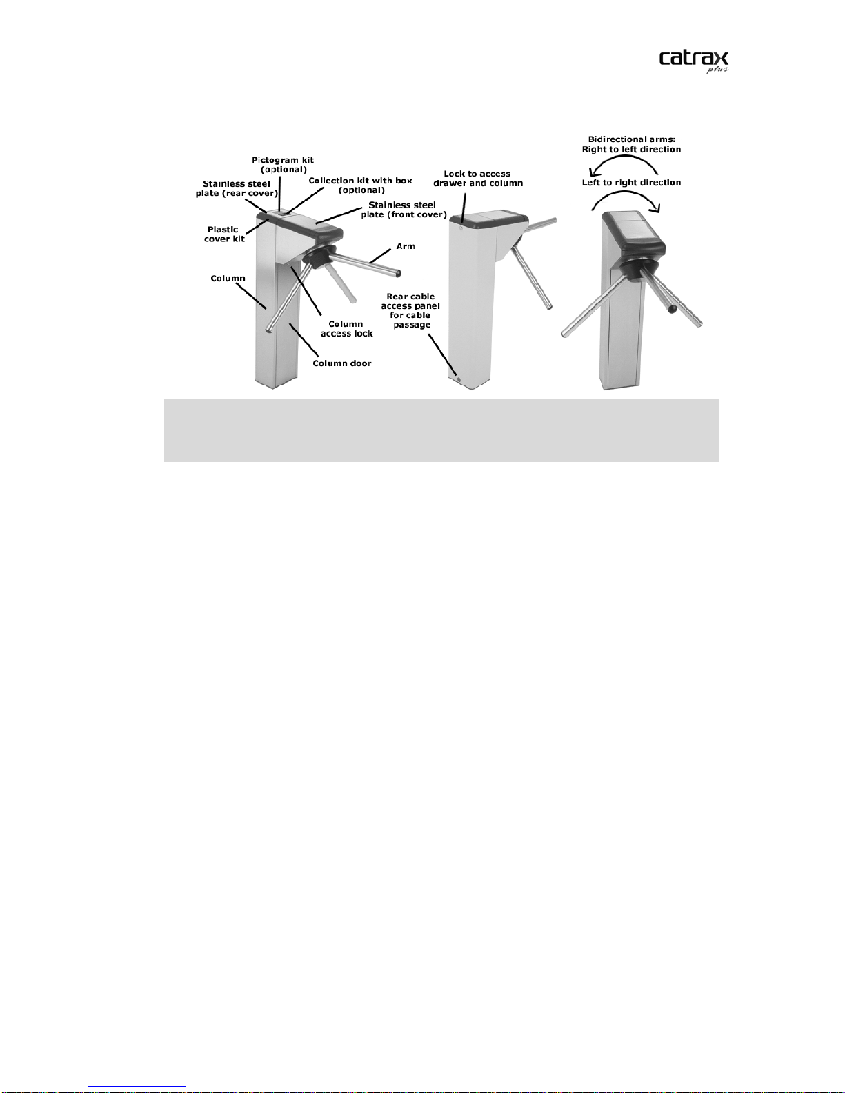
The figure below shows all the parts that may come with your CATRAX Plus:
NOTE
In addition to the items indicated above, the CATRAX Plus may include an optional
counter, a power supply unit, a control board, a no-break power unit, and a
pictogram kit.
4.2 P
REPARING THE INSTALLATION SITE
Before installing CATRAX Plus, pl ease v e rify that:
1. The site chosen for installation is adequate – keep in mind that the turnstile must
be installed indoors.
2. There is an energy source or electric outlet close to where the turnstile will be
installed.
4. There is enough room (at least 5 cm) between the rear part of the CATRAX Plus
column and the wall. This is important to ensure access to the upper panel and rear
cable access panel.
5. There is enough room for the arms to turn. For additional details concerning
equipment dimensions, see item 7 Technical Characteristics, page 23 .
6. The floor has the necessary support structure for anchor bolts (suggested minimum
of 4 cm of FCK15 MPa concrete or equivalent).
NSTALLING THE COLUMN
4.3 I
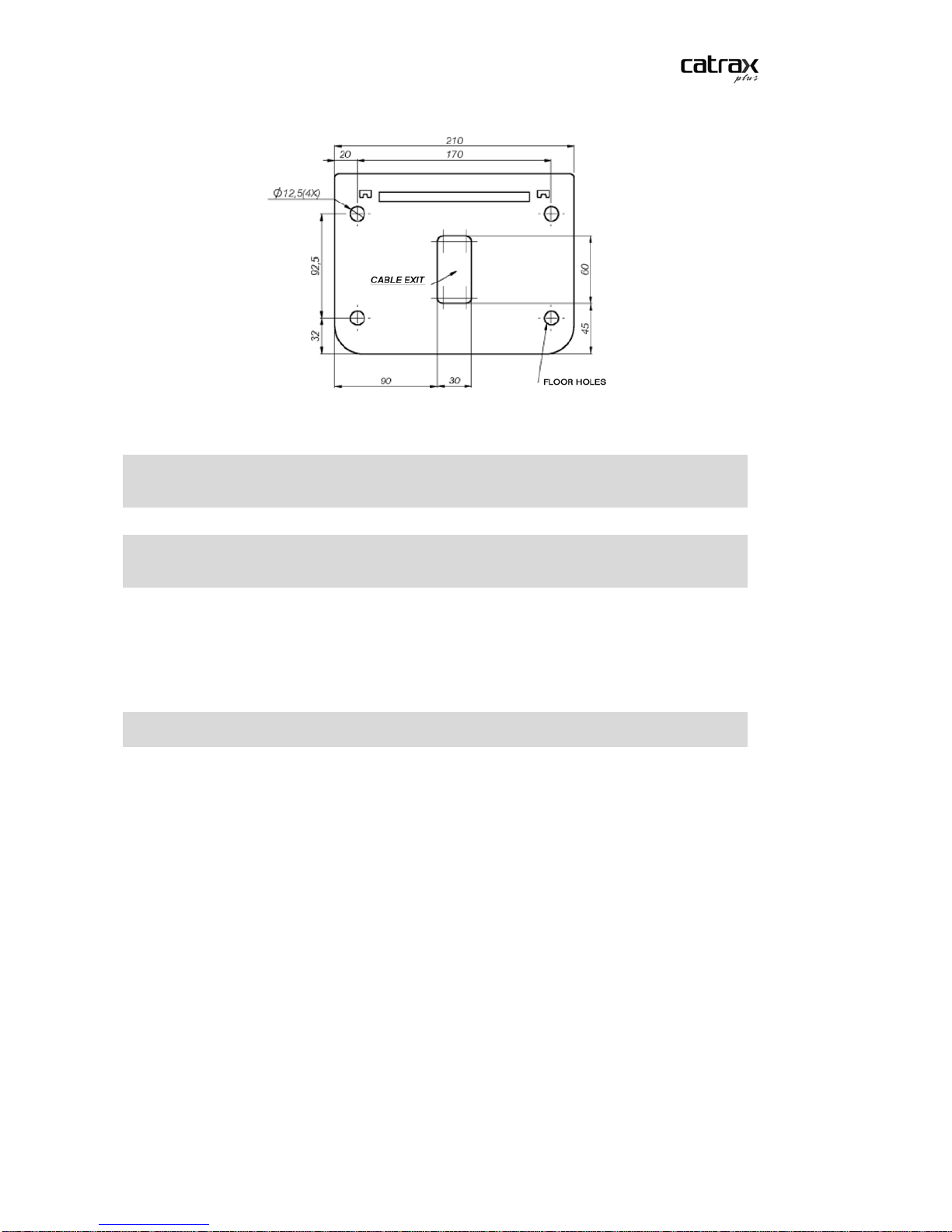
1. Drill the floor with a 3/8” (9.5 mm) drill and finish with a 1/2” (12.5 mm) drill.
Make four holes as indi cated in the diagram below.
7
Product Manual
Dimensions in mm.
NOTE
Electrical and communication cables must pass through the cable exit. Check cutout dimensions to make sure all cables will fit.
NOTE
A heavy-duty steel template for installation of the column may be purchased from
Digicon.
2. Clean the holes, removing drilling residues.
3. Place the four anchor bol t s in the holes, leaving approximately 25 mm of the anchor
bolt out of the hole.
NOTE
Recommended bolts: Tecmart AF38110, 3/8x4”.
4. Position the column and fasten it onto the floor with the four bolts that come with
the anchor bolts. Use a 3/4” socket wrench or spanner.
4.4 M
OUNTING OF ARMS AND COVERS
After installing the column, you may proceed with mounting the arms and plastic
covers.
The details of the arms and top front cover and the instructions for assembly appear in
the figure below.
8

Product Manual
NOTE
Use a #5 Allen wrench to mount the CATRAX Plus.
After that, mount the upper panel rear cover. T h e following figure shows the cover in
detail.
4.5 ACCESS TO THE CATRAX PLUS INTERNAL COMPONENTS AFTER ASSEMBLY
After the CATRAX Plus has been installed and assembled, access to in ternal
components is possible via the rear cover, the front cover, or the column door, using
the access keys that come wi th the equipment.
5 INSTALLATION/ASSEMBLY OF OPTIONAL
PRODUCTS
Digicon offers several options to enhance access control and facilitate customization.
5.1 C
The collection kit with chute has a card and badge collection, retention and storage
unit, perfect for visitors or temporary users. The kit is composed of a plastic insertion
slot, a solenoid-activated retention mechanism and a storage box. The following figure
shows the items that come with the collection kit and may serve as a g uide for its
assembly.
ARD COLLECTION KIT WITH CHUTE
9
 Loading...