

CAT Pumps 1XP Series, 1XP075, 1XP085, 1XP050, 1XP100 Installation, Operational And Repair Manual
...Page 1
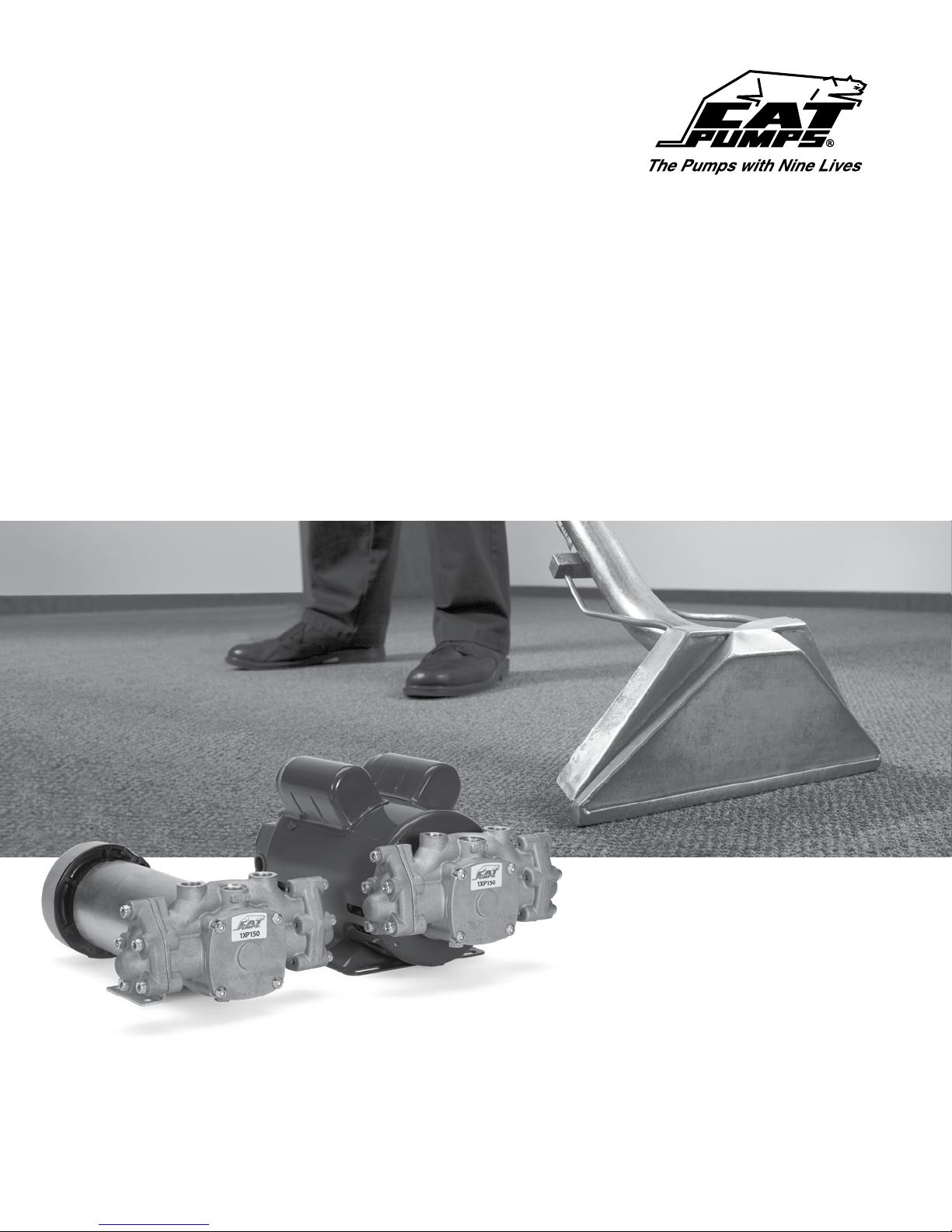
1XP Series
Plunger Pump
Installation, Operational and Repair Manual
Product Quality, Reliability and Support You Expect
www.catpumps.com
Page 2
Introduction
This manual is intended to assist in installing pump and motor
unit, startup and shutdown unit, troubleshoot, disassembly and
reassembly of pump. An exploded view and parts list have also been
provided to assist in identifying individual components, along with
a torque chart.
Safety
IMPORTANT SAFETY INSTRUCTIONS
It is the responsibility of the user to read and understand all
instructions, important safeguards, and safety precautions
before operating or servicing any pump. Failure to do so may
result in property damage, personal injury or death.
Table of Contents
Introduction 2
Safety 2
Important safety instructions 2
General safety information and symbols 2
Safety Hazards 2-5
Pump Models and Pump/Motor Assemblies 6
Technical Features (i.e., ow, pressure, rpm, Hp) 6
Pump and motor installation 6-7
(Electrical Power Connection and Plumbing Connection)
Preliminary inspection 8
Start up instructions 8
Shut down instructions 8
Parts list 8
Exploded view 9
Pump disassembly 10 -12
Pump reassembly 13-16
DC Motor (8136) brush replacement 17
Stopping for long periods 17
(i.e., long term and/or winterization)
Restarting system 17
Torque specications and repair tools 18
Preventative maintenance 18
Troubleshooting 18
(i.e., problem – cause – solution)
Flow and Pressure 19
Cat Pumps Warranty 20
GENERAL SAFETY INFORMATION AND
SYMBOLS
Pay special attention to the following signal words, safety
alert symbols and statements:
Indicates a hazardous situation which,
if not avoided, will result in death or
serious injury.
Indicates a hazardous situation which,
if not avoided, could result in death or
serious injury.
Indicates a hazardous situation which,
if not avoided, could result in minor or
moderate injury or property damage.
Indicates a hazardous situation which,
if not avoided, could result in property
damage.
Indicates a potential personal injury
hazard. Obey all safety messages that
follow this symbol to avoid possible
injury or death.
Safety Hazards
A. FLAMMABLE OR EXPLOSIVE LIQUID HAZARD
Do not operate pump with ammable or explosive liquids unless extraordinary safety precautions are
observed. Leaks of ammable or explosive liquids, if exposed to elevated temperatures, static electricity,
sparks or other hazards, will result in ame or possible explosion, causing serious personal injury, death
or property damage.
1. Before operating pump with ammable or explosive liquids, ensure proper maintenance has been performed.
2. Do not operate pump with ammable or explosive liquids if leaks are detected.
3. Only pump ammable or explosive liquids that are compatible with pump component materials.
4. Do not operate pump with ammable or explosive liquids without safeguards or safety systems to detect leaks,
elevated temperatures, spark prevention or any other hazards dened by the NFPA systems.
5. Do not remove Flammable Liquids Product Suitability Hang Tag to assure proper safety.
6. Follow ATEX guidelines for potentially explosive atmospheres.
2
Page 3

A. ELECTRICAL SHOCK HAZARD
Do not service pump or electrical equipment while energized. Electricity can cause personal injury,
death or property damage.
1. Adhere to “Lock Out” and “Tag Out” procedures for electrical equipment.
2. Before commencing pump service, turn power supply o.
3. Keep water away from electrical outlets and electrical devices.
4. Electrical components must be installed by a qualied electrician to avoid risk of electrocution.
B. ROTATING PARTS HAZARD
Do not service pump while energized. Moving, rotating or reciprocating parts can crush and cut, causing
personal injury, death or property damage.
1. Adhere to “Lock Out” and “Tag Out” procedures for electrical equipment.
2. Before commencing pump service, turn power supply o, turn water supply o, squeeze trigger on gun to relieve
system pressure.
3. For mobile equipment, be sure engines and hydraulics are turned o and secured to avoid accidental start.
4. Do not operate with safety guards removed.
5. Always use safety guards on all belt drives, couplings and shafts.
C. HOT SURFACE HAZARD
Do not touch pump, accessories or drive system while operating and until cool down is complete. Touching
hot surface areas of the pump, accessories or drive system can cause severe burns or personal injury.
D. SKIN PUNCTURE HAZARD
Do not allow spray to contact any part of the body or animals. Pumped liquids under high pressure can pierce
skin and underlying tissue or can deect debris leading to serious personal injury or death.
1. Relieve all line pressure in the inlet line to the pump and discharge line from the pump before performing any
maintenance on the pump.
2. When high pressure gun is not in use, set safety trigger lock (safety latch) to avoid accidental high pressure
operation and personal injury or property damage.
3. Do not check for leaks with hand. Use a piece of cardboard to check for leaks.
4. Review cleaning procedures to minimize heavy back blasting.
5. Wear adequate safety equipment and clothing when operating high pressure sprayer. Never use high pressure
spray with bare feet or exposed skin, and always wear safety glasses.
E. PUMPING LIQUIDS HAZARD
Do not operate pump with hot water, chemicals, or other hazardous liquids unless extraordinary safety
precautions are observed. Pumping hot water, chemicals, or other hazardous liquids can expose personnel to
serious injury.
1. Provide guards or shields around equipment to protect personnel.
2. Wear mask, goggles or eye protection while operating high pressure equipment.
3. Obtain a material safety data sheet (MSDS) and take appropriate safety measures for the liquid being handled.
F. OVER PRESSURIZATION HAZARD
Do not operate high pressure pumping system unless extraordinary safety precautions are observed.
A high pressure pumping system can deadhead or over pressurize causing serious personal injury and
property damage.
1. All high pressure systems require a primary pressure regulating device (i.e., regulator or unloader) and a secondary
pressure safety relief device (i.e., pop-o valve, safety valve, rupture disc) to assure proper pressure setting and
overpressure protection.
2. All high pressure systems require a pressure gauge to monitor pressure settings and avoid overpressure of
equipment or personal harm.
3. Install primary pressure relief device on the discharge side of the pump.
4. Install secondary pressure relief device between the primary device and pump.
5. Install pressure gauge onto the discharge manifold or in the discharge line near the manifold.
6. Open all valves on discharge side of plumbing before operation.
3
Page 4
Continued
G. OXYGEN HAZARD
Do not charge Prrrrr-O-Lators (Pulsation Dampeners) with oxygen. Oxygen may cause an explosion causing
personal injury, death or property damage.
1. Use nitrogen only when charging pulsation dampeners, DO NOT USE OXYGEN.
2. Use proper charging tools to charge pulsation dampeners.
3. Charge pulsation dampener within specications stated on data sheet to assure proper pulsation dampening and
prevent failure of bladder.
H. FALL HAZARD
Do not operate pressure washer while standing on slippery or unstable surface unless extraordinary safety
precautions are observed. Pressure washing may create slippery surface on which a person may slip and fall
causing personal injury or death.
1. Wear suitable footwear to maintain a good grip on wet surfaces.
2. Do not stand on ladders or scaolding.
3. Do not over reach or stand on unstable supports.
4. Keep good footing and balance and hold gun with both hands to control kick back.
A. IMPROPER USE OF FITTINGS HAZARD
Do not operate the pump with improperly connected, sized, worn or loose ttings, pipes or hoses. Operating
the pump under these conditions could result in personal injury and property damage.
1. Ensure all ttings, pipes and hoses are properly rated for the maximum pressure rating and ow of the pump.
2. Check all ttings and pipes for cracks or damaged threads.
3. Check all hoses for cuts, wear, leaks, kinks or collapse before each use.
4. Ensure all connections are tight and secure.
5. Use PTFE thread tape or pipe thread sealant (sparingly) to reconnect plumbing. Do not wrap tape beyond the last
thread, this will prevent tape from becoming lodged in the pump or accessories.
6. Apply proper sealants to assure secure t or easy disassembly when servicing.
B. FROZEN LIQUID HAZARD
Do not operate the pump with frozen liquid. Operating the pump under this condition could over pressurize
and jettison the manifold from the crankcase causing personal injury and property damage.
1. Store pump or pumping system in an environmentally controlled room protected from freezing temperatures.
2. Follow procedures in TECH BULLETIN 083 to winterize pump.
C. CLEANING PUMP HAZARD
Do not use solvents that are ammable and toxic to clean or degrease equipment. Use of these solvents could
result in personal injury and property damage.
1. Follow safety instructions as found in MSDS or on packaging of each liquid.
2. Clean equipment in a well ventilated area.
3. Disposal of solvents to be in accordance with local, state and federal regulations.
D. OPERATING BEYOND SPECIFICATIONS HAZARD
Do not operate the pump outside the specications of individual pump data sheet or service manual.
Operating the pump under these conditions could result in personal injury and property damage.
1. Do not operate the pump faster than the maximum recommended RPM.
2. Do not operate the pump at pressures higher than the maximum
recommended pressure.
3. Do not operate the pump at temperatures higher than the maximum recommended temperatures.
4. Do not use accessories that are not compatible or rated for the pump.
4
Page 5
Continued
E. LIFTING DEVICE HAZARD
Do not lift pump with unsuitable lifting devices. Use of unsuitable lifting devices may cause pump to fall
resulting in personal injury, damage to pump and/or pump with drive/base plate.
1. Lifting eyes installed on the pump must be used only to lift the pump.
2. Special lifting eyes should be installed on the base for lifting the pumping system (i.e. base, drive and accessories)
3. If slings or chains are used for lifting, they must be safely and securely attached to properly balance the weight
of the unit.
4. Inspect slings and chains prior to use and replace worn and damaged slings and chains.
A. ROTATION OF PUMP HAZARD
Do not rotate pump crankshaft in reverse direction. Rotation of pump crankshaft in reverse direction may
not provide proper lubrication and may result in damage to the drive-end components.
1. Forward rotation is the top of the crankshaft turning towards the manifold head of the pump.
2. Ensure oil is lled to the center red dot on sight gauge for forward rotation.
3. Ensure oil is lled to slightly above center red dot on sight gauge for reverse rotation.
B. BELT TENSION HAZARD
Do not operate pump with excessive belt tension. Excessive belt tension may damage the pumps bearings or
reduce horsepower.
1. Rotate pump crankshaft before starting to ensure shaft and bearings are moving freely.
2. Ensure pulleys are properly sized.
3. Periodically replace belts to assure full horsepower transmission.
4. Ensure center distance dimensions between pulleys is correct.
C. BY-PASS OPERATION HAZARD
Do not operate the pump in by-pass for extended lengths of time. Operating the pump under this condition
can quickly cause heat build-up resulting in damage to the pump.
1. Route by-pass line to supply reservoir to dissipate heated by-pass liquid into a large reservoir of cool water to
reduce excessive temperature build-up.
2. Route by-pass line to inlet of pump using a thermo valve in the by-pass line or auto shut-o assembly that will sense
temperature rise and either by-pass or shut down system before damage occurs.
D. DRY OPERATION HAZARD
Do not operate the pump without water or liquid. Operating pump under these conditions could result in
damage to the pump.
1. Open all valves on inlet side of pump before starting operation to prevent starving the pump.
2. Do not exceed inlet suction pressure limit specied in pump Data Sheet.
3. Ensure inlet feed exceeds the maximum ow being delivered by the pump.
4. Ensure all ttings, pipes and hoses are properly sized for the pump to avoid restricted ow.
5. Review and implement all other recommendations appropriate for your system from the Inlet Condition Check-List.
5
Page 6
Pump Models and Pump/Motor Assemblies
The 1XP series pumps are being oered
as pump only or as a motorized pump
assembly. Column one of the chart covers
the pump only with ow ranges from
0.5 gpm (1XP050) to 2.0 gpm (1XP200).
Column two of the chart covers the “AC”
motor and pump assemblies with 1/3, 1/2,
3/4 and 1 HP motor options.
Columns three, four and ve of the chart
covers “DC” motor and pump assemblies
with only a 1/3 HP motor option.
Pump
Model
1XP050 1XP050.031, 1XP050.051 1XP050.03DC 1XP050.03DC2 1XP050.03DCT
1XP075 1XP075.031, 1X P075.0 51 1XP075.03DC 1XP075.03D C2 1XP075.03DC T
1XP085 1XP085.031, 1XP085.051 1XP085.03DC 1XP085.03DC2 1XP085.03DCT
1XP100 1XP100.031, 1XP10 0.051 1XP100.03DC 1X P10 0.03D C2 1XP10 0.03D CT
1XP125 1XP125.031, 1XP125 .051 1X P125.03DC 1X P12 5.0 3DC 2 1XP125.03DCT
1XP150
1XP180 1XP180.071, 1XP180.101 — — —
1XP20 0
Pump/Motor
Assy – AC
1XP150.031, 1XP150.051,
1XP150.071, 1XP150.101
1XP20 0.031, 1XP200. 051,
1XP20 0.071, 1XP20 0.101
120V ODP 240V ODP TEFC
1XP150.03DC 1XP150.03DC 2 1X P150.03D C T
1XP20 0.03D C 1XP200.03DC2 1XP2 00. 03 DCT
Pump/Motor Assy – DC
Technical Features
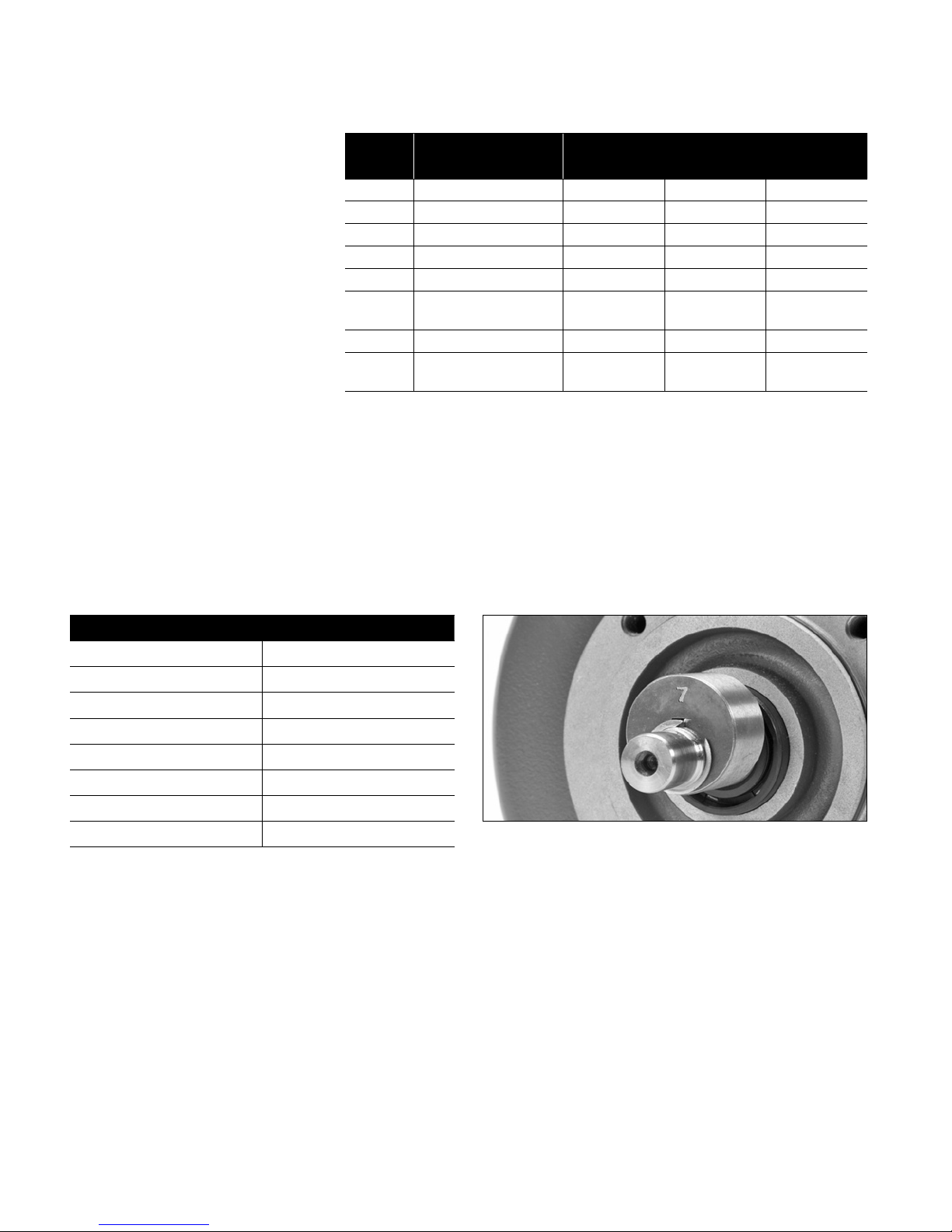
There are eight (8) cams available for the 1XP Series Pumps. Each cam is numbered from 1 to 8, with the smallest number 1 indicating the
lowest ow starting at 0.50 gpm, up to the largest number 8 indicating 2.00 gpm. If a label has been removed or destroyed, simply remove
bearing cover and check stamped number on cam. Use chart to verify which stamped number applies to your model of pump. Each pump
model number also helps identify the ow of your pump, See chart below.
Pump Model Cam ID number
1XP050 1
1XP075 2
1XP085 3
1XP100 4
1XP125 5
1XP150 6
1XP20 0 7
1XP180 8
Stamped Cam ID number (See Chart)
Pump and Motor Installation
Due to the variety and uniqueness of each extractor machine that is available, there are multiple ways of installing the 1XP motorized
pump unit. Please read and follow existing extractor operational manual when removing pump and motor from machine. Follow all safety
instructions. Use the following steps to properly wire and plumb the new 1XP series pumps.
1.1 Position assembled pump and motor (AC or DC) into extractor machine.
1.2 Secure assembled unit to extractor base using hole pattern of motor.
6
Page 7
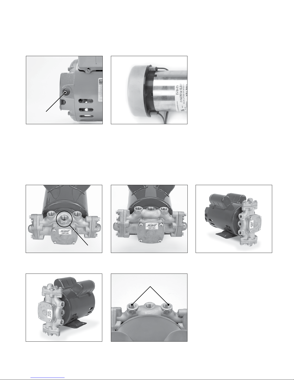
Electrical power connection:
Power Cord
Connection
1.3 Connect to power source for AC
(induction) motors 8133, 8135 and 8147
(115/208-230VAC).
1.4 Connect to power source for DC
(permanent magnet) motor 8136, 8139
(120 Volt - rectied) and 8138 (240 Volt rectied)
Plumbing connection:
NOTE: Standard pump to motor mounting is shown in gure 1.5 (inlet port facing out). Figures 1.6, 1.7 and 1.8 are optional ways
of mounting pump to motor.
Inlet Port
1.5 Install inlet water hose to center 3/8”
NPT port on pump labeled “INLET”
1.6 Pump inlet port facing motor.
1.7 Pump inlet port rotated 90°counterclockwise in a vertical position.
1.8 Pump inlet port rotated 90°clockwise
in a vertical position.
Discharge Ports
1.9 Install discharge accessories or water
hoses to two (2) 3/8” NPT ports
labeled “OUT”
7
Page 8
Preliminary Inspection Parts List
After inlet hose, discharge hose and/or accessories have been
installed to ports of pump crankcase follow the preliminary steps as
outlined below prior to startup.
2.1 Ensure all hoses and ttings are tight.
2.2 Ensure water is supplied to the pump before starting.
2.3 Ensure regulating device is set or backed o to the lowest
setting.
2.4 Ensure there is power to the motor.
2.5 Ensure there is water in supply tank of extractor machine.
Start Up Instructions
The 1XP pump requires a gravity fed inlet, and can be used on
pressurized inlets up to 40 psi. Do not starve the pump or run the
pump dry. Note: AMP draw will be elevated during 1st hour of
operation. After 1.0 hour, AMP draw will drop by 10%. Follow the
steps as outlined to ensure properly operation.
3.1 Turn on water supply to the pump.
3.2 Turn on power to pump.
3.3 Open discharge to atmosphere to purge air from system.
3.4 Adjust regulating device to desired pressure.
Shut Down Instructions
To stop the pump in an emergency, turn
o power to pump and relieve all line pressures by triggering gun
handle. Under normal conditions follow the steps as outlined below.
4.1 Turn o power to pump.
4.2 Turn o water supply to pump.
4.3 Squeeze and hold trigger gun to relieve discharge line pressure.
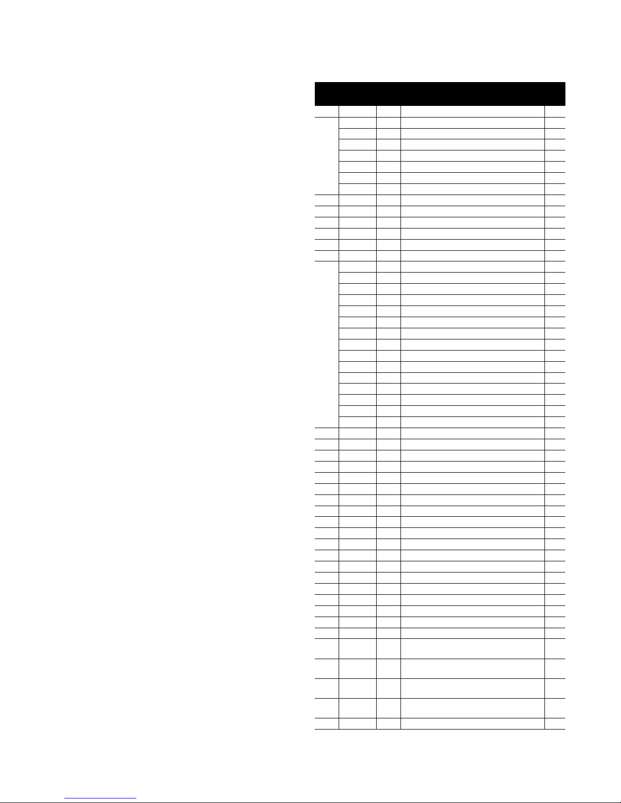
Item
No.
1 76801 AL Crankcase 1
2
3 31527 BB Plug (1/8"- 27NPT) 1
4 76928 STZP Screw, Button Hea d (M6 X 75) 4
5 76346 AL Cover, Bearing Keyed Shaft 1
6 31552 FPM O-ring, Bearing Cover - 70D 1
7* 76701 S Ring, External Retaining 1
8
9* 76025 SFSS Key, Woodru (#405) 1
10 76133 FPM Seal, Shaft w/SS Flange 1
11 3159 6 FPM O-ring, Slinger - 70D 1
12 31552 FPM O-Ring, Motor Flange 1
13 76909 STZP Screw, (HSH) (M6 X 30) [01/14] 10
14 76420 AL Cover, Head 2
15 31592 FPM O-ring, Head Gasket - 70D 2
16 31577 S Nut (M6) 2
17 31584 S Washer, Conical (M6) 2
18 44872 S Spring 2
19 3159 5 S Spacer 2
20 76226 NY Valve, Inlet 2
21 45429 CC Plunger (M18 X 16) 2
22 43245 SNG Seal, High Pressure W/Spring 2
23 35426 FPM O-ring, Valve Seat - 90D 2
24 76576 D Seat, Dischar ge Valve [01/14] 2
25 76206 S Valve, Discharge 2
26 76 865 S Spring, Valve [06/13] 2
27 76069 PVDF Retainer, Valve 2
28 76555 AL
29 76227 NY
30 76218 FPM
31 76219 FPM
32 76127 – Ki t, Brush Replacement (8136 only) 1
Part
Number Matl
8133 Motor, 1/3 HP (AC), Keyed Shaft 1
8135 Motor, 1/2 HP (AC), Keyed Shaft 1
8147 Motor, 3/4 HP (AC), Threaded Shaft 1
8148 Motor, 1.0 HP (AC), Threaded Shaft 1
8136 Motor, 1/3 HP (DC), ODP, 120 VAC, Keyed Shaf t 1
8138 Motor, 1/3 HP (DC), OD P, 240 VAC, Keyed Shaf t 1
8139 Motor, 1/3 HP (DC), TEFC, 120 VAC, Keyed Shaf t 1
76539 AL Cover, Bearing Threaded Shaft 1
76520.050 SFSS #1 Cam (0.50 gpm, 1750 rpm) Keyed 1
76520.075 SFSS #2 Cam (0.75 gpm, 1750 rpm) Keyed 1
76520.085 SFSS #3 Cam (0. 85 gpm, 1750 rpm) Keyed 1
756 20 .100 SFSS #4 Cam (1.00 gpm, 1750 rpm) Keyed 1
76520 .125 SFSS #5 Cam (1.25 gpm, 1750 rpm) Keyed 1
76520.150 SFSS # 6 Cam (1.50 gpm, 1750 rpm) Keyed 1
76520.200 SFSS #7 Cam (2. 00 gpm, 1750 rpm) Keyed 1
7654 0.050 SFSS #1 Cam (0.50 gpm, 1750 rpm) Threaded 1
7654 0.075 SFSS #2 Cam (0.75 gpm, 1750 rpm) Threaded 1
7654 0.085 SFSS #3 Cam (0.85 gpm, 1750 rpm) Threaded 1
756 20 .100 SFSS #4 Cam (1.00 gpm, 1750 rpm) Threaded 1
7654 0.125 SFSS #5 Cam (1.25 gpm, 1750 rpm) Threaded 1
765 40.15 0 SFSS #6 Cam (1.50 gpm, 1750 rpm) Threaded 1
7654 0.200 SFSS #7 Cam (2.00 gpm, 1750 rpm) Threaded 1
765 40.18 0 SFSS #8 Cam (1.80 gpm, 1750 rpm) Threaded 1
Assembly, Plunger/Connecting Rod
(Includes: p lunger rod, connec ting rod & wrist pin)
(Includes: items 16, 17, 18, 19, 20)
Assembly, Discharge Valve
(Includes: items 23, 24, 25, 26, 27)
(Includes: items 6, 10, 11, 12, 15, 22)
AL = Aluminu m, BB = Brass, CC = Ceram ic, D = Acetal, FPM = Fluo rocarbon, N Y = Nylon,
PVDF = Poly vinyliden e Fluoride, S = 304 St ainless Steel , SFSS = 17-4 Stai nless Steel,
SNG = Speci al Blend (Buna), ST ZP = Steel/Zin c Plated, [xx /xx] = Date of Lates t Productio n Change.
*Only us e with Keyed Shaf t Motors
Description
Kit, Inlet Valve
Kit, Seal and O-ring
Qty
2
1
1
1
8
Page 9
13
17
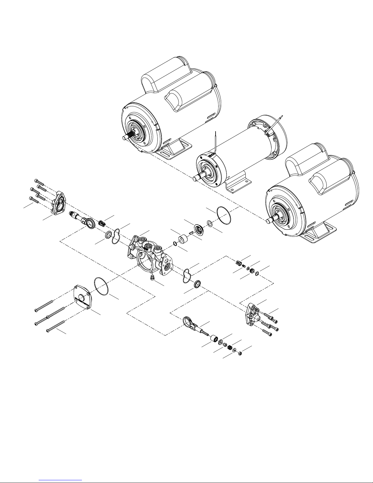
Exploded View
AC Motor
(Threaded Shaf t)
30
14
22
DC Motor
(Keyed Shaf t)
12
15
1
10
8
11
9
7
15
AC Motor
(Keyed Shaf t)
27
25
23
26
24
3
6
5
4
22
28
20
18
21
19
14
13
16
9
Page 10
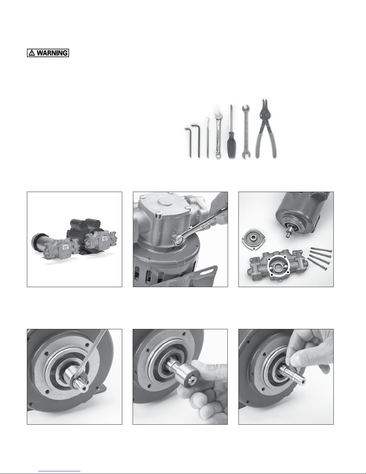
Pump Disassembly
Do not service pump or electical equipment while energized.
Electricity can cause personal injury, death or property damage.
1. Adhere to “Lock Out” and “Tag Out” procedures for electrical equipment.
2. Before commencing pump service, turn power supply o.
3. Keep water away from electrical outlets and electrical devices.
4. Electrical components must be installed by a qualied electrician to avoid risk of electrocution.
Tools Required
1. 4mm (M4) Allen Wrench
2. 5mm (M5) Allen Wrench
3. Pick
4. 10mm Open Wrench
5. 13mm Open Wrench
6. Flathead Screwdriver (2)
7. 1/2” Open Wrench
8. Spanner Wrench
NOTE: Numbers in ( ) refer to item numbers in exploded view.
1 2 3 4/5 6 7 8
5.1 Disconnect plumbing and wiring to
motor. Remove pump and motor
assembly from machine.
5.4 Use a screwdriver to remove retaining
ring (7) from motor shaft.
(Keyed Shaft only)
10
5.2 Use a 13mm wrench to remove brass
drain plug (3) from pump crankcase (1)
to drain water.
5.5 Remove and inspect cam (8) from
motor shaft.
5.3 Use a 4mm allen wrench to seperate
pump (1) from motor (2) by removing
four (4) M6x75 button head screws (4)
from bearing cover (5).
5.6 Remove and inspect woodru key (9)
from keyway of motor shaft.
(Keyed Shaft only)
Page 11
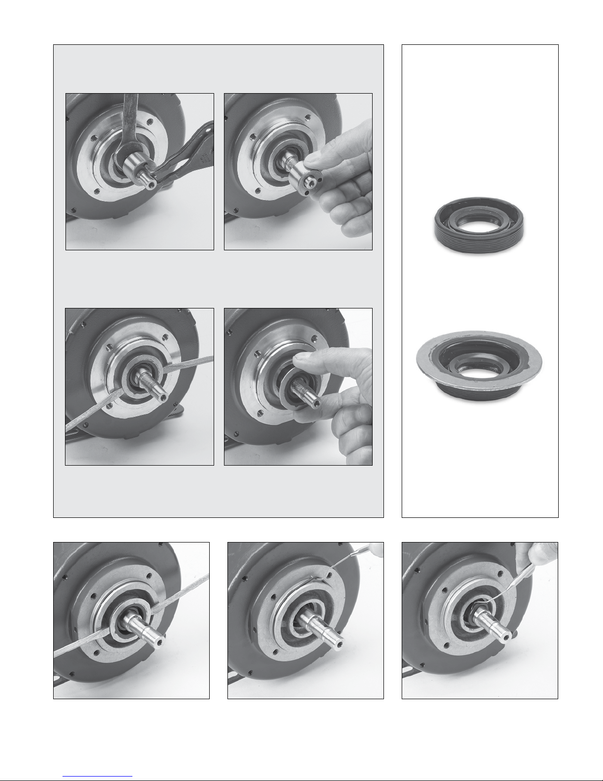
For Threaded Shaft Units:
NOTICE
If old shaft seal cannot be
removed, it may require removing
motor cover.
(See Service Bulletin 002)
5.7 Place 1/2" open wrench behind cam
(8) onto motor shaft. Position tips of
spanner-wrench into two holes of
cam and turn to loosen.
5.9 Insert two (2) at tip screw drivers
between ange and pry shaft seal
away from motor.
5.8 Unthread threaded cam from motor
shaft
5.10 Remove and inspect shaft seal (10)
from motor ange. Do not scratch or
damage motor shaft surface.
Old Shaft Seal
New Shaft Seal
5.11
5.12 Remove and inspect shaft seal (10)
from motor ange. Do not scratch or
damage motor shaft surface.
5.13 Use a pick tool to remove motor ange
o-ring (12) from motor ange.
5.14 Use a pick tool to remove slinger o-ring
(11) from motor ange.
11
Page 12
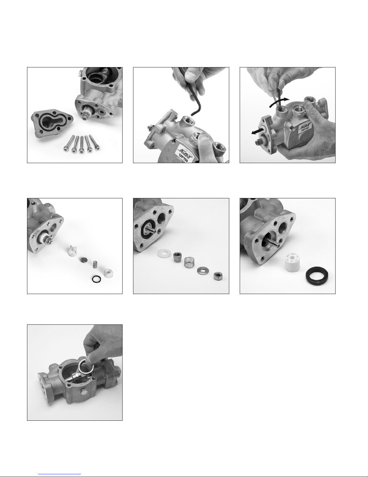
Pump Disassembly continued
NOTE: Inlet valve, discharge valve, high pressure seal and plunger are identical in both cylinder heads.
5.14 Use a 5mm allen wrench to remove
ve (5) M6x30 screws (13) holding head
cover (14) to crankcase body.
5.17 Separate and inspect retainer (27),
spring (26), valve (25), seat (24), and
o-ring (23).
5.15 Insert the short end of an allen wrench
to remove discharge valve assembly.
5.18 Remove and inspect nut (16), washer
(17), spacer (19), spring (18) and inlet
valve (20).
5.16 Pivot 5M allen wrench against top
of spring retainer and push valve
assembly out.
5.19 Remove and inspect ceramic plunger
(21) and high pressure seal (22) from
crankcase body (1).
5.20 Remove and inspect connecting rod,
plunger rod and wrist pin assembly.
12
Page 13
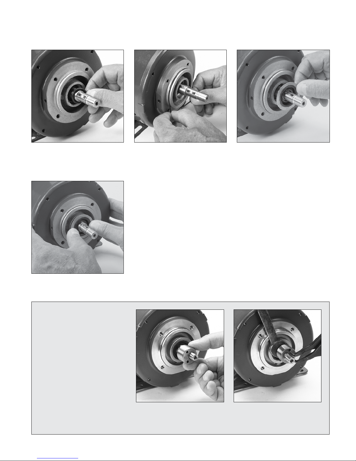
Pump Reassembly
6.1 Lubricate and install slinger o-ring (11)
into motor ange by sliding over motor
shaft. Center between shaft seal bore
and back of the slinger seal bore.
6.4 Press stainless steel ange rmly against
motor ange until completely seated.
6.2 Lubricate and install motor ange
o-ring (12) onto the motor ange.
6.3 Lubricate and install shaft seal (10)
with stainless steel ange facing out
(towards pump).
For Threaded
Shaft Units:
Loctite a nd 242 are regis tered trademark s of the Henkle Corp oration
6.5 Hand thread cam (8) with stamped ID
number and small holes facing pump
(clockwise).
6.6 Use spanner wrench and 1/2" open
wrench to tighten cam (8).
NOTE: Apply Loctite® 242® to threads
of motor shaft.
13
Page 14
Pump Reassembly continued
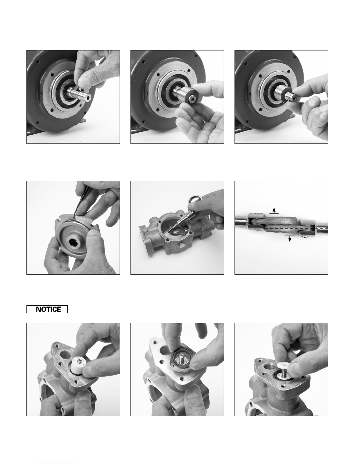
6.7 Lubricate and install woodru key (9)
into motor shaft keyway. (Keyed Shaft
only).
6.10 Lubricate and install o-ring (6) onto
bearing cover (5).
Be careful not to damage the bushing ID in the case, as the plunger rod thread passes through the bushing.
6.8 Lubricate and install cam (8) over
motor shaft and key. Position cam (8)
so stamped cam ID number is facing
pump. (Keyed Shaft only).
6.11 Install plunger rod/connecting rod
assembly through large opening in
crankcase body (1).
6.9 Install retaining ring (7) into snap
ring groove on motor shaft to secure
cam (8). (Keyed Shaft only).
Out
Out
Eliminates
Interference
6.12 Protruding cast face of connecting
rods should face away from each other
inside crankcase (1).
6.13 Install ceramic plunger (21) with
recessed face away from crankcase.
14
6.14 Lightly lubricate and install high
pressure seal (22) with v-groove facing
up over ceramic plunger (21).
6.15 Install inlet valve (20) with at side
down onto plunger (21).
Page 15
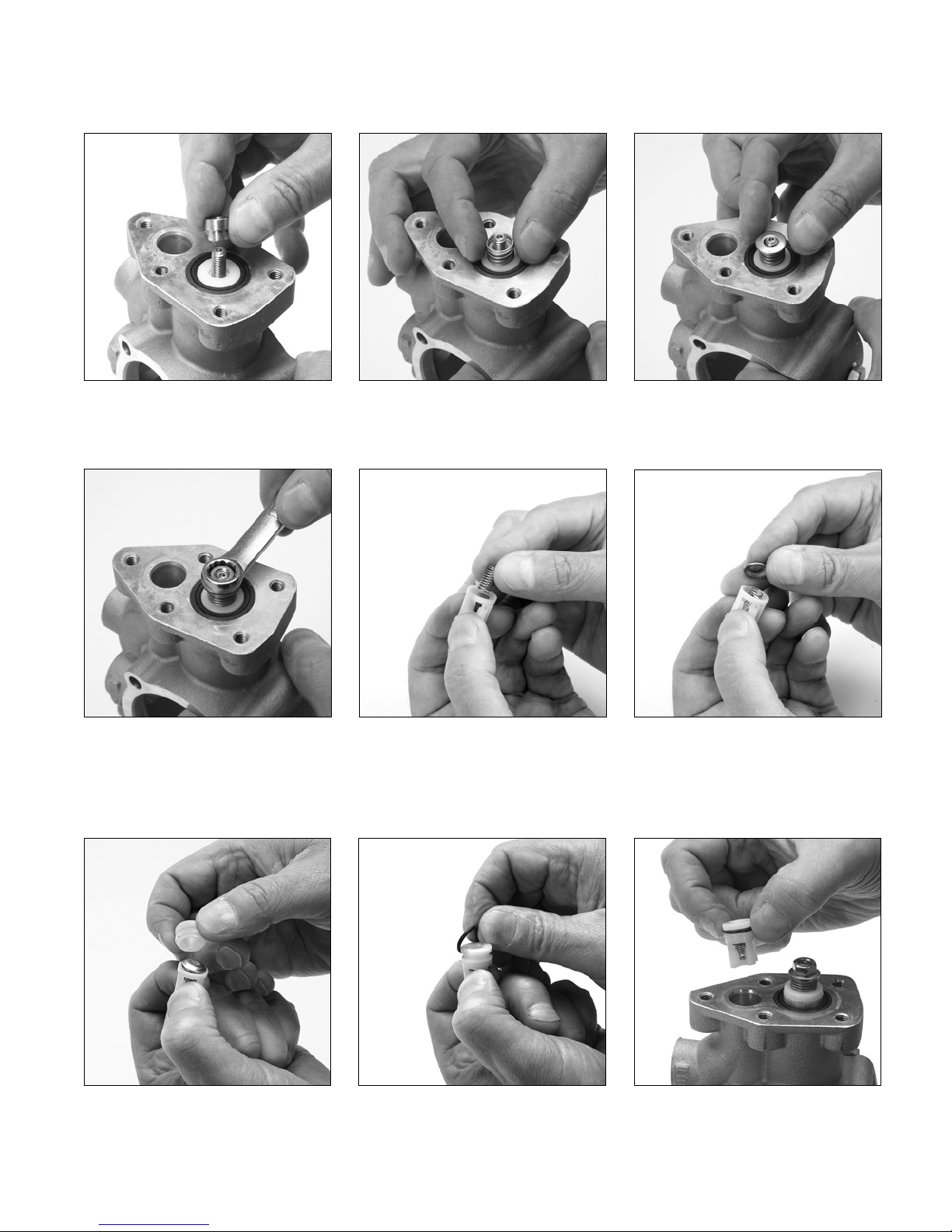
6.16 Install spacer (19) small diameter down
into inlet valve (20).
6.17 Install spring (18) over spacer (19) and
on to inlet valve (20).
6.18 Install washer (17) with curved surface
down on to spring (18).
6.19 Apply Loctite®242® to M6 threads on
plunger rod. Thread nut (16) onto M6
threads of plunger rod and torque to
25 in-lbs.
6.22 Place tapered side of seat (24) towards
retainer (27) and snap into place.
Loctite a nd 242 are regis tered trademark s of the Henkle Corp oration
6.20 Assemble the discharge valve as follows:
6.23 Lubricate and install o-ring (23) to seat
Insert spring (26) into retainer (27).
(24). Repeat for second valve assembly.
6.21 Place valve (25) cupped side over the
spring (26).
6.24 Press discharge valve assembly (30)
into top hole with retainer facing into
crankcase body (1) until ush with
cylinder head surface.
15
Page 16
Pump Reassembly continued
3
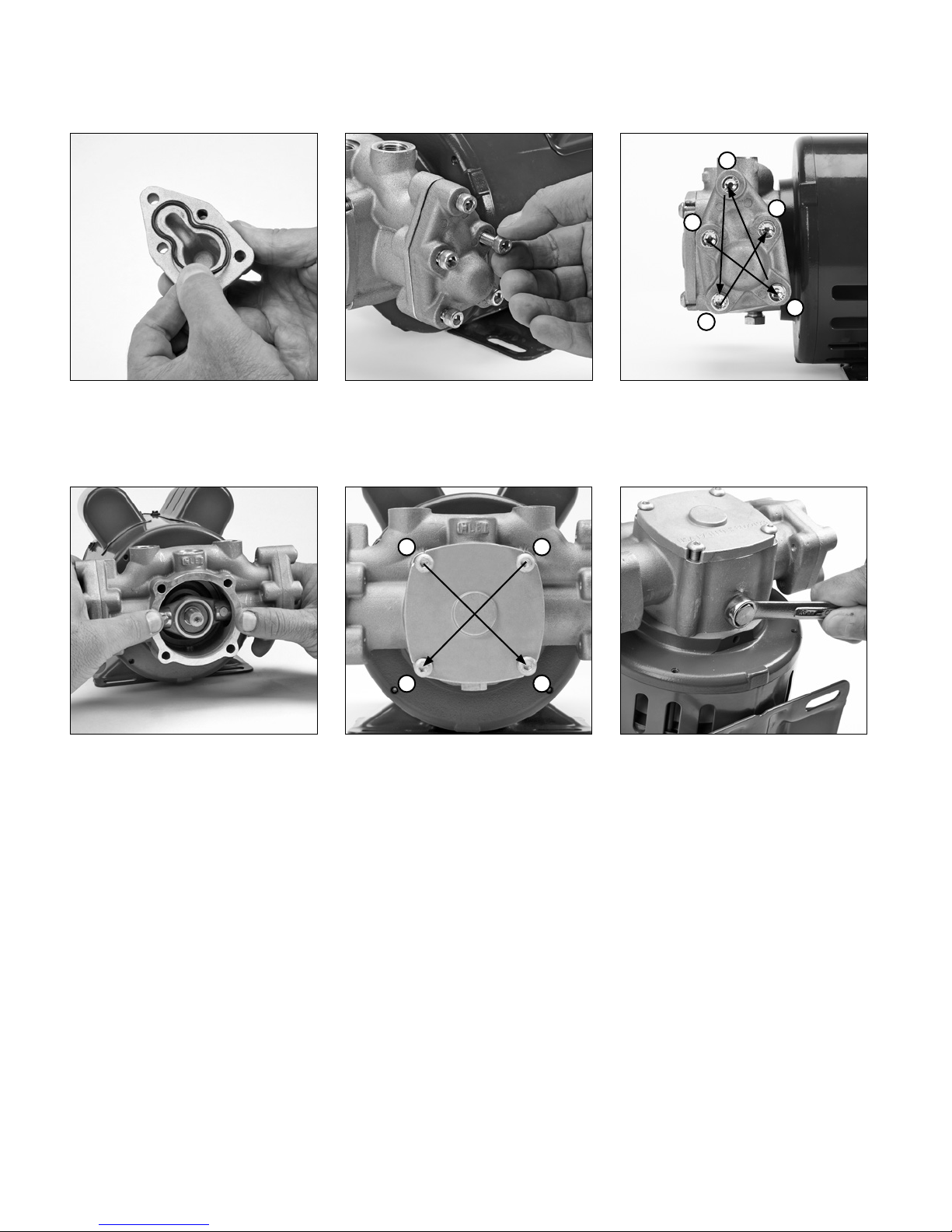
6.25 Lubricate and install o-ring (15) into
head cover. Repeat for other cylinder
head.
6.26 Position head cover (14) onto
crankcase body (1) and hand thread
in ve (5) M6x30 screws (13).
1
1
5
2
4
6.27 Use a 5mm allen wrench to torque to
102 in-lbs in sequence as shown.
3
6.28 With bearing cover (5) removed,
position crankcase body (1) onto motor
while lining up the connecting rods (28)
with the cam (8).
Note: Make sure the connecting rods are
loose on cam.
4
6.29 Hand thread four (4) M6x75 button
head screws (4). Use a 4mm allen
wrench to torque to 48 in-lbs in
sequence as shown.
Note: Lubricate o-ring on bearing
cover prior to installing.
2
6. 30 Use 13mm wrench to install drain plug (3)
into bottom port of crankcase body (1).
16
Page 17
DC Motor (8136 only) Brush Replacement
DISASSEMBLY
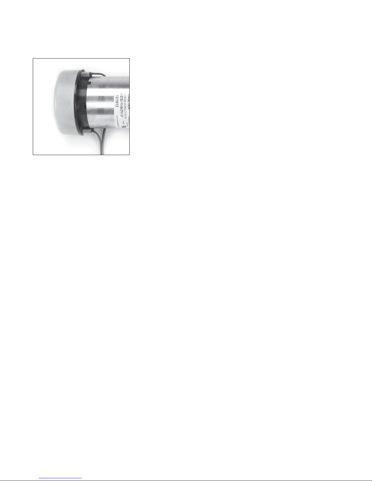
7.1 Place at tip of screwdriver between the
top of the white retaining clip and end
cover and pry upwards to provide small
separation between cover and motor
housing.
7.2 Using same screwdriver, remove white
retaining clip.
7.3 Remove wire lead from small opening in
motor housing.
7.4 Blow out dust that may accumulate in
opening of motor.
7.5 Repeat steps 7.1 to 7.4 to remove second
wire lead.
Stopping for Long
Periods
REASSEMBLY
7.6 Position wire lead into opening of motor
with brush and attaching spring down
into opening with brass end facing up.
7.7 Place white retaining clip over wire lead
and snap into place.
7.8 Using a soft mallet, tap end of cover
into place.
7.9 Repeat steps 7.6 to 7.8 to reassemble
second wire lead.
Restarting
System
If the extractor unit will not be operated for a long period of time or
needs to be placed in storage, please follow these steps to protect
the pump.
8.1 Flush pump with fresh water.
8.2 Turn o power supply.
8.3 Squeeze trigger gun to relieve discharge line pressure.
8.4 Disconnect inlet and discharge plumbing.
8.5 Connect a short 4 foot hose to the pump inlet and place the
other end of the hose in a container with 50% water and 50%
antifreeze.
8.6 Start the unit and run until the antifreeze ows out the discharge
of the pump.
8.7 Shut the unit o and disconnect the hose from the pump inlet.
8.8 Store unit (do not install plugs in the inlet and discharge ports).
If the extractor unit has been shut down for any length of time, the
following steps should be used as a guideline to ensure the proper
restarting and resetting of the pump.
9.1 Turn regulator/unloader setting to lowest pressure point.
9.2 Reconnect the liquid supply line, discharge line and allow liquid
to ow through pump for 2-3 minutes.
9.3 Check for leaks at all plumbing connections.
9.4 Gradually reset regulator/unloader in small increments to desired
system pressure and resume operation.
9.5 Follow your established maintenance cycle or the standard
Preventative Maintenance checklist in this manual.
17
Page 18
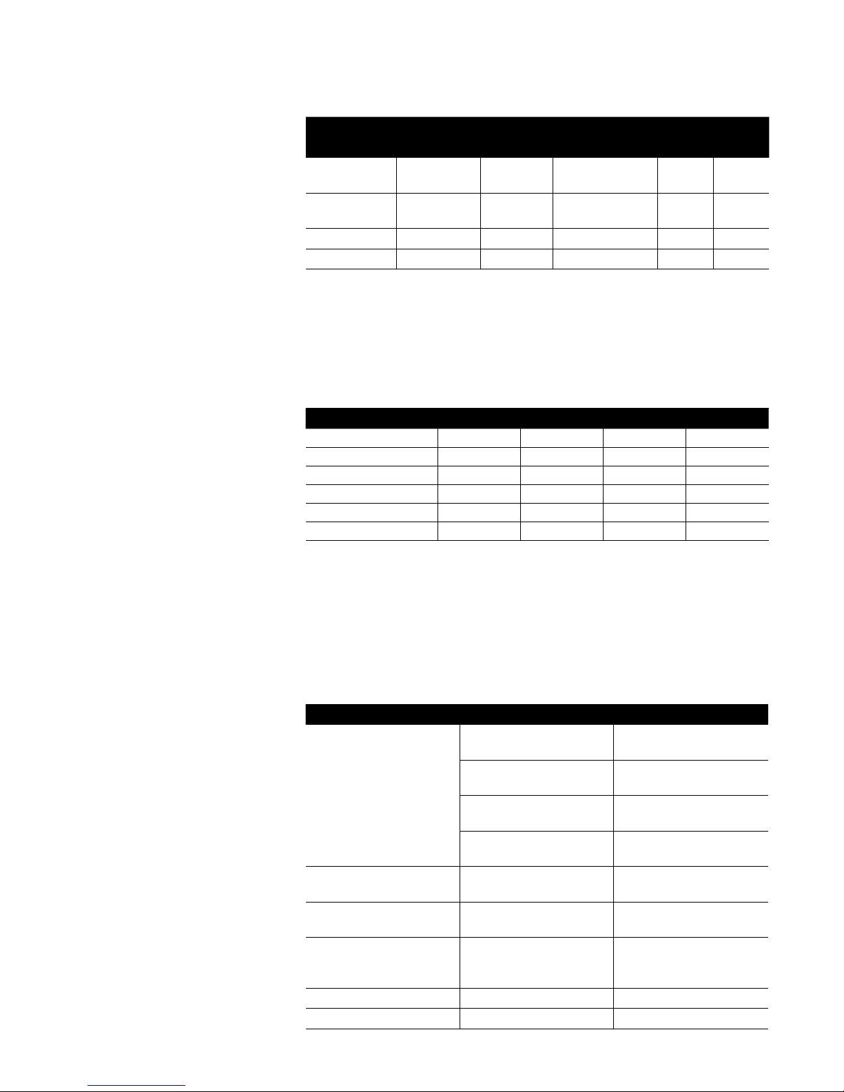
Torque Specifications and Repair Tools
Torque valves (in-lbs) and sequences are
referenced in each section as it applies.
This chart provides the same values, but
also expands to “ft-lbs” and “Nm”, as well as
supplies thread sizes and tools required.
Item Thread Tool Size in - lbs ft - lbs N - m
Bearing cover
screws (front)
Head cover
screws (side)
Inlet valve nut M6 M10 Hex 25 2.08 2.70
Drain plug 1/8” - 27 NPT M13 Hex “Water tight seal” – –
M6 M4 Allen 48 4.00 5.20
M6 M5 Allen 102 8.50 11.05
Preventative Maintenance
Periodic maintenance and adjustment
is necessary to keep the pump in good
operating condition. Perform the service
and inspection scheduled in the table.
Use only genuine Cat Pumps parts or kits
when performing repairs.
Check Daily Weekly 600 Hours 1000 Hours
Water leaks x
Plumbing x
Seal change x
Inlet valve change x
Discharge valve change x
Brushes (8136 Motor) x
Torque
Troubleshooting
The troubleshooting table has been
provided to assist in dening problems
that may arise, then giving probable causes
to look for and nally providing possible
solutions to the problem at hand.
18
Problem: Probable Causes: Solutions:
Low pressure Worn nozzle Replace with proper size
nozzle
Worn seals Install new seal kit. Increase
frequency of service
Air leak in inlet plumbing Tighten ttings and hoses.
Use PTFE liquid or tape
Worn or dirty inlet/
discharge valve
Water leak at head cover Worn or pinched o-ring
on head cover.
Water leak at bearing cover Worn or pinched o-ring
on bearing cover
Premature seal failure Running dry, scored
plungers, abrasives,
contamination
Scored plunger Abrasives, contamination Replace plunger
Motor stalls or will not start Brushes worn Replace with Brush Repair Kit
Clean inlet/discharge valves
or install new valve kit.
Install new seal kit. Increase
frequency of service.
Install new seal kit. Increase
frequency of service
Replace seals
Page 19
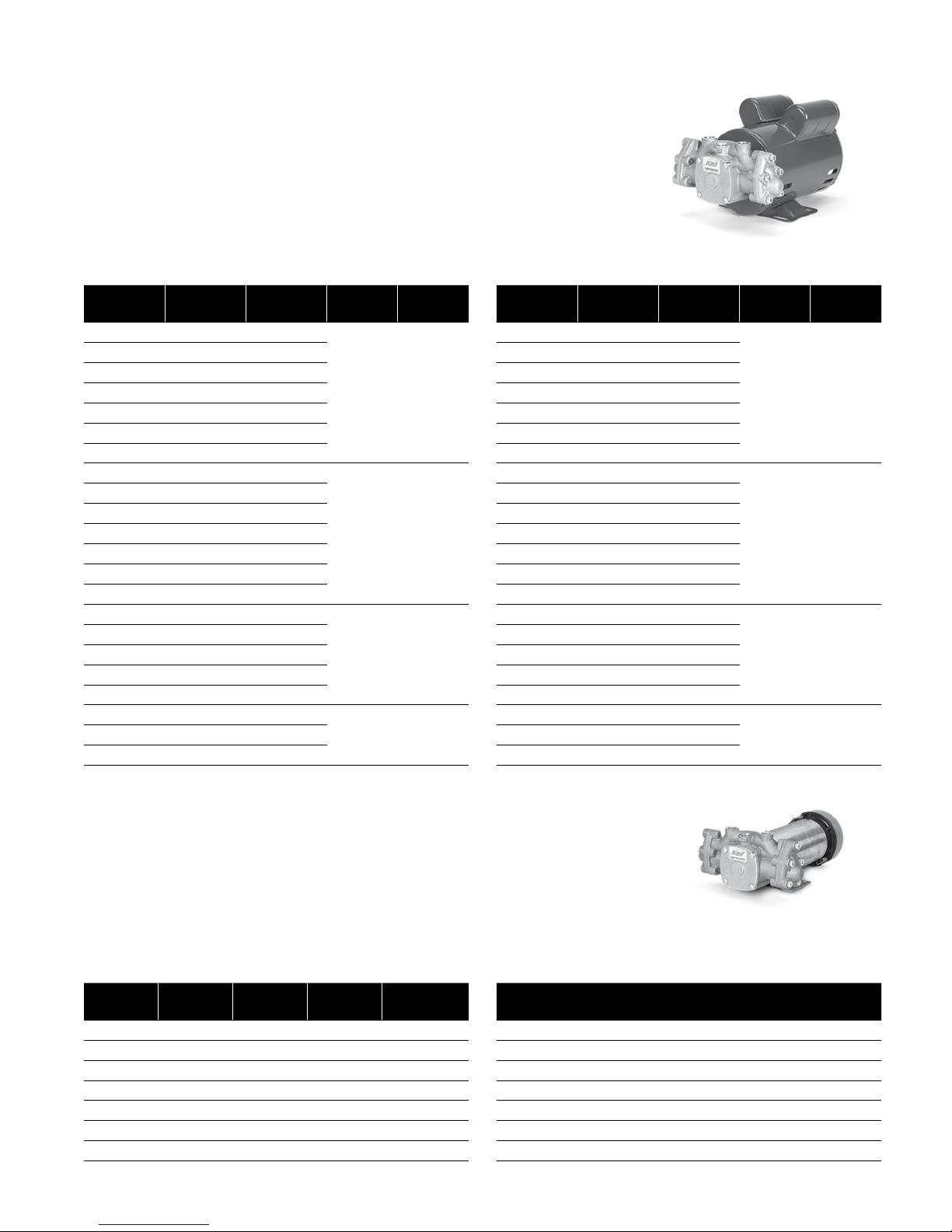
Flow and Pressure
1XP Pump with AC Induction Motor
AC Induction Motor – 60 Hz, 120V (1750 rpm)
GPM Max PSI
0.5 600 1XP050.031
0.75 500 1XP075.031
0.85 500 1XP085.031
1 450 1X P10 0.031
1.25 400 1XP125.031
1.5 325 1XP150 .031
2 250 1XP20 0.031
0.4 1000 1XP050.051
0.7 1000 1XP075.051
0.8 1000 1XP085.051
0.9 800 1XP100.051
1.2 800 1XP125. 051
1.5 600 1XP150.051
2 450 1XP200 .051
0.9 1000 1XP100.071
1.1 1000 1XP125. 071
1.4 800 1XP150.071
1.75 700 1XP180.071
2 550 1XP200. 071
1.45 1000 1XP150.101
2 750 1XP200 .101
Pump
Assembly
SFA
4.0/2.0 1/3
8.0/4.0 1/2
9.0/4.5 3/4
12.6/6.3 11.8 800 1XP180.101
HP
AC Induction Motor – 50 Hz, 240V (1450 rpm)
GPM Max PSI
0.40 600 1XP050.031
0.60 500 1XP075. 031
0.70 500 1XP085.031
0.80 450 1XP10 0.031
1 400 1XP125. 031
1.2 325 1XP150 .031
1.70 250 1XP20 0.031
0.30 1000 1XP050.051
0.60 1000 1XP075.051
0.70 1000 1XP085.051
0.75 800 1XP100.051
1 800 1XP125. 051
1.2 600 1XP150.051
1.70 450 1XP200.051
0.75 1000 1XP10 0.071
0.90 1000 1X P12 5.071
1.20 800 1XP150. 071
1.50 700 1XP180 .071
1.70 550 1XP2 00. 071
1.20 1000 1XP150.101
1.70 750 1XP200.101
Pump
Assembly
SFA
4. 2/2 .1 1/3
8.2/3.8 1/ 2
10.0/4.6 3/4
13. 6/6.3 11.40 800 1X P18 0.101
HP
1XP Pump with DC Permanent Magnet Motor
DC Permanent Magnet – 120 Volt - 1/3 HP
ODP and TEFC Enclosures
GPM Max PSI
0.5 600 4.0 1XP050.03DC 1XP050.03DCT
0.75 500 4.0 1X P075.03D C 1XP075.03DC T
0.85 400 4.0 1XP085.03DC 1XP085.03DCT
1 350 4.0 1XP100.03DC 1XP10 0.03D CT
1.25 300 4.0 1X P125.03DC 1XP125. 03D C T
1.5 250 4.0 1XP150 .03DC 1XP150.03DC T
2.3 150 4.0 1XP20 0.03D C 1XP200 .03DC T
Amps
(at max psi)
Pump Assembly
ODP Motor
Pump Assembly
TEFC Motor
DC Permanent Magnet – 240 Volt - 1/3 HP
ODP
GPM Max PSI
0.5 600 2.0 1XP050.03DC2
0.75 500 2.0 1XP075.03DC2
0.85 400 2.0 1XP085.03DC2
1 350 2.0 1XP100.03DC2
1.25 300 2.0 1XP125.03DC2
1.5 250 2.0 1XP150.03DC2
2.3 150 2.0 1XP200.03DC2
Amps
(at max psi)
Pump Assembly
ODP Motor
19
Page 20
Cat Pumps Limited Warranty
Cat Pumps warrants that each of the following products will be free from defects in material and workmanship for the time
period provided:
• ONE YEAR from the date of sale for 1XP Series Pumps.
• 90 DAYS from the date of sale for accessories.
Cat Pumps will repair or replace (in its sole discretion) each product subject to this limited warranty that Cat Pumps verifies as
having defects in original materials or workmanship. REPAIR OR REPLACEMENT IS THE SOLE AND EXCLUSIVE REMEDY
AVAILABLE UNDER THIS LIMITED WARRANTY. The Cat Pumps limited warranty is conditioned upon the prepaid return of the
product claimed to be defective per Cat Pumps RGA Policy. For RGA policy details contact Cat Pumps. The repaired or replacement
Product will be returned to the original purchaser transportation pre-paid. If inspection of the product does not disclose any defect
in materials or workmanship, you will be notified for approval of any repairs that may include cost of parts, labor, and transportation
or the cost of a replacement product. Any repaired or replacement product provided under this limited warranty will be
subject to the warranty period applicable to the original product and no additional warranty is provided.
This limited warranty applies only when the Product is installed, operated and maintained in accordance with the applicable
Cat Pumps’ written Pump Service Manual, Data Sheets (available on-line at www.catpumps.com) and Cautions and Warnings
(available on-line at www.catpumps.com) for the Product. Cat Pumps makes no warranty on standard wear items such as,
but not limited to, seals, valves, seats and o-rings. This warranty does not cover, and Cat Pumps shall not be liable for, defects
or failures resulting from improper or lack of maintenance, lack of proper crankcase lubrication, failure to supply adequate liquid
to pump, pumping materials below 5 pH or above 9 pH, above 500 cps, general wear and tear, or any malfunction, damage or
wear caused by faulty installation, misapplication, misuse, accident, excessive abrasion, corrosion, freezing or heat, tampering,
substitution of genuine Cat Pumps parts, or disassembly and/or repairs not performed by Cat Pumps. This warranty also does not
cover, and Cat Pumps shall not be liable for, any malfunction, damage or wear caused by the incompatibility of any Cat Pumps’
Product with structures, accessories, products or materials not supplied by Cat Pumps. In addition, Cat Pumps makes no warranty,
and disclaims all implied warranties of merchantability and fitness for a particular purpose, in connection with products, materials
or components sold, but not manufactured, by Cat Pumps, such as, but not limited to motors, gas or diesel engines, gear drives.
THE WARRANTIES AND REMEDIES CONTAINED HEREIN ARE EXCLUSIVE AND IN LIEU OF ALL OTHER WARRANTIES,
WHETHER EXPRESS, IMPLIED OR STATUTORY, INCLUDING ANY LIABILITY ARISING UNDER ANY WARRANTY OF
MERCHANTABILITY OR FITNESS FOR A PARTICULAR PURPOSE. CAT PUMPS DISCLAIMS AND IN NO EVENT SHALL
CAT PUMPS BE LIABLE FOR INDIRECT, INCIDENTAL OR CONSEQUENTIAL DAMAGES OF ANY KIND, REGARDLESS OF
HOW THEY MAY OCCUR. ANY ACTION FOR BREACH OF WARRANTY MUST BE BROUGHT WITHIN 1-YEAR FROM THE
DATE OF THE ALLEGED BREACH.
FOR CAT PUMPS CANADA CUSTOMERS
The parties acknowledge that they have required that the present document, as well as all documents, notices and legal
proceedings entered into, given or instituted pursuant or relating directly or indirectly hereto, be drawn up in English. Les parties
reconnaissent avoir convenu que la rédaction du présente document sera en anglais, ainsi que tous documents, avis et procedures
judiciaires executés, donnés ou intents à la suite de ou en rapport, directement ou indirectement, avec les procedures concernées.
CAT PUMP S
1681 94TH LANE N.E. MINNEAPOLIS, MN 554494324
PHONE 763 7805440 FAX 763 7802958
e-mail: [email protected]
www.catpumps.com
For International Inquiries go to www.catpumps.com and navigate to the “Contact Us” link.
PN 993456 Rev E 8/18
 Loading...