

CAT Pumps 1530, 1531, 1540, 1540E, 1560 Service Manual
...
15 & 25PFR PLUNGER PUMP SERVICE MANUAL
15 FRAME SPLIT MANIFOLD : 1530, 1531, 1540, 1540E, 1560
25 FRAME SPLIT MANIFOLD : 2510, 2511
INSTALLATION AND START-UP INFORMATION
Optimum performance of the pump is dependent upon the entire liquid system and will be obtained only
with the proper selection, installation of plumbing, and operation of the pump and accessories.
SPECIFICATIONS : Maximum specications refer to individual attributes. It is not
implied that all maximums can be performed simultaneousl y. If more than one
maximum is considered, check with your CAT PUMP S supplier to conrm the proper
performance and pump selection. Refer to individual pump Data Sheets for complete
specications, parts list and exploded view.
LUBRICATION: Fill crankcase with special CAT PUMP oil per pump specications
(15PFR- 42 oz. , 25P FR-8 4 oz.). DO NOT R UN P UMP WIT HO UT OIL IN CR AN KC ASE .
Change initial ll after 50 hours running period. Thereafter, change oil every 3 month s
or 500 hour
of operation and temperature.
PUMP ROTATION : Pump was designed for forward rotation to allow optimum lubrication of the crosshead area. Reverse rotation is acceptable if the crankcase oil level
is increased slightly above center dot to assure adequate lubrication.
PULLEY SELECTION: Select size of motor pulley required to deliver the desired
ow from Horsepowe r Requirement and Pulley Selection Cha rt (refer to Tec h
Bulletin 003 or individual Data Sheet).
MOTOR SELECTION: The motor or engine driving the pump must be of adequate
horsepower to maintain full RPM when the pump is under load. Select the electric
motor from the Hor sepower Requirement Chart according to required pump
discharge ow, maximum pressure at the pump and drive losses of approximately
3-5% . Consult the manufacturer of gas or diesel engine for selection of the proper
engine size.
MOUNTING: Mount the pump on a rigid, horizontal surface in a manner to permit
drainage of crankcase oil. An un even mounting sur face will cause extensive
damage to the pump base. To minimize piping stress, use appropriate exibl e
hose to inlet and discharge port s . Use the correct belt; make sure pulleys are
aligned. Excessive belt tension may be harmful to the bearings. Hand rotate pump
before starting to be certain shaft and bearings are free moving.
LOCATION : If the pump is used in extremely dirty or humid conditions, it is recommen ded pump be enclosed. Do not store or operate in excessively high temperature
areas or without proper ventilation.
INLET CONDITIONS: Refer to complete Inlet Condition Check-List in this manual
before s tarting s ystem. D O NOT ST ARVE THE PUMP O R RUN DRY .
Temperatures above 130°F are permissible. Add 1/2 PSI inlet pressure per eac h
degree F over 130°F. Elastomer or RPM changes may be required. See Tec h
Bulletin 002 or call CAT PUMPS for recommendations.
C. A .T. : Ins ta llation of a C. A.T. (C aptive A cce leration Tu be) is rec ommended in
applic ations with stre s sful inle t co nditions su ch as high tempe ratures , booste r
pump feed, long inlet lines or quick closing valves.
intervals. Additional lubrication may be required with increased hours
DISCHARGE CONDITIONS: OPEN ALL VALVES BEFORE STARTING SYSTEM to
avoid deadhead overpressure condition and severe damage to the pump or sy stem.
Install a Pulsation Dampenin g device on the discharge head or in the discharge line
as close to the head as possible. Be cer
properly precharged for the system pressure (refer to individual Data Sheet) .
A reliable Pressur e Gaug e should be installed near the discharge outlet of the
high pressure manifold. This is extremely important for adjusting pressure regulating
devices and also for proper sizing of the nozzle or restricting orice. The pump is
rated for a maximum pressure; this is the pressur e which would be read at the
discharge manifold of the pump , NOT AT THE GUN OR NOZZLE.
Use PTFE thread tape or pipe thread sealant (sparingly) to connect accessories or
plumbing. Exercise caution not to wrap tape beyond the last thread to avoid tape
from becoming lodged in the pump or accessories. This condition will cause a malfunction of the pump or system.
PRESSURE REGULATION: All systems require both a primary pressure regulating
device (i.e., regulator, unloader) and a secondary pressure safety relief device (i.e.,
pop-o valve, safety valve). The primary pressure device must be installed on the
discharge side of the pump. The function of the primary pressure regulating device
is to protect the pump from over pressurization, which can be caused by a plugged
or closed o discharge line. Over pressurization can severely damage the pump,
other system components and can cause bodily harm. The secondary safety relief
device must be installed in-line between the primary device and the pump or on
the opposite side of the manifold hea d. This will ensure pressure relief of the
system if the primary regulating device fails. Failure to install such a safely device
will void the warranty on the pump.
When the high pressure system is left running with the trigger gun o, the by-pass
liquid can be routed to drain or to the pump inlet. If routed to the pump inlet, the
by -pas s liqui d ca n qu ickl y dev elop exc ess iv e he at an d result in dama
the pump . A THERMO VALVE installed in the by-pass line is recommended to
protect the pump. An AUTO SHUT-OFF ASSEMBLY may also be used.
NOZZLES: A worn nozzle will result in loss of press ure. Do not adjust press ure regulating device to compensate. Replace nozzle and reset regulating device to syste m
pressure.
PUMPED LIQUIDS: Some liquids may require a ush between operations or befor e
storing. For pumping liquids other than water, contact your CA T PUMP S supplier.
STORING: For extended storing or between use in cold climates, drain all pumped
liquids from pump and ush with antifreeze solution to prevent freezing an d
damage to the pump. DO NOT RUN PUMP WITH FROZEN LIQUID (refer to Tech
Bulletin 083).
tain the pulsation dampener (Prrrrr-o-lator) is
ge to
All systems require both a primary pressure regulating device (i.e., regulator, unloader) and a secondary pressure safety relief device (i.e., pop-o valve, safety valve).
Failure to install such relief devices could result in personal injury or damage to the pump or to system components. CAT PUMP S does not assume any liability or responsibility
for the operation of a customer’s high pressure system .
Pijttersen B.V.
Postbus 262, 8500 AG Joure
Transportwei 26, 8501 ZP Joure
WARNING
Tel.: +31 (0)513-414040
Fax: +31 (0)513-414066
E-mail : info@pijttersen.nl / info@catpumps.nl
Internet : www.pijttersen.nl / www.catpumps.nlThe Netherlands
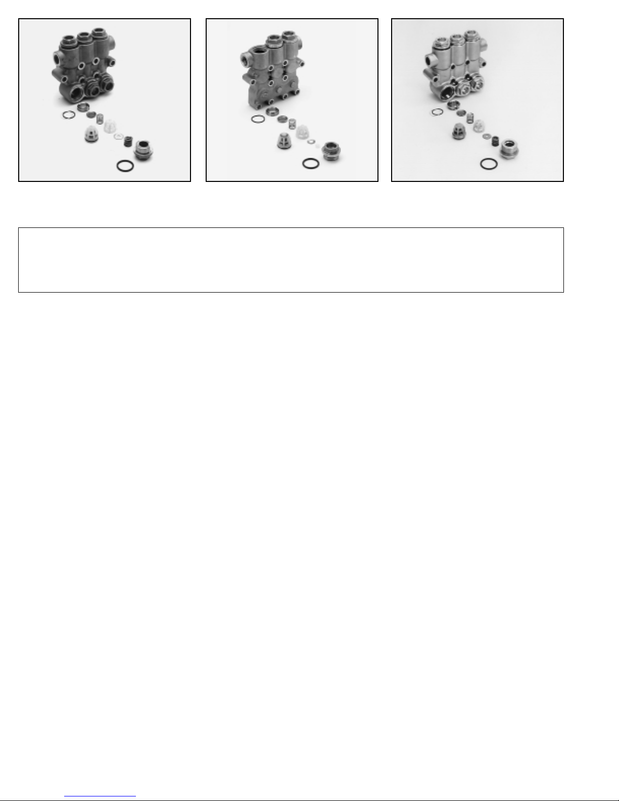
1530, 1531
Complete Inlet/Discharge Valve Assembly
CAUTION: Before commencing with service, shut off drive (electric motor, gas or diesel engine) and turn off water supply to pump. Relieve all discharge line pressure by triggering gun or opening valve in discharge line.
After servicing is completed, turn on water supply to pump, start drive, reset pressure regulating device and secondary valve, read system pressure on the
gauge at the pump head. Check for any leaks, vibration or pressure fluctuations and resume operation.
Inspect and service all system accessories on the same schedule as your pump.
1540, 1540E
Complete Inlet/Discharge Valve Assembly
2510, 2511
Complete Inlet/Discharge Valve Assembly
SERVICING THE VALVES
Disassembly
1. Models 1530 1531, 1540, 1540E, 2510, 2511: Remove the hex
valve plugs with o-ring.
Model 1560: Remove the eight (8) hex socket head (HSH)
screws and valve cover. Remove valve plugs with o-ring and
back-up-ring.
2. Models 1530 1531, 2510, 2511: Remove the exposed coil
spring and washer from the top of the spring retainer.
Models 1540 and 1540E: Remove washer from the top of the
spring retainer.
3. Models 1530, 1531, 1540, 1540E, 2510 and 2511: Using a
pliers to grasp the spring retainer by the tab at the top and remove from valve chamber. Normally the valve assembly will
remain together. If the assembly separates during removal,
use a reverse pliers and lift the seats from the chamber.
Model 1560: Use a reverse pliers to grasp the spring retainer
and remove the stacked valve assemblies.
4. To separate valve assemblies, insert screwdriver into spring
retainer and press the backside of valve until seat separates
from the spring retainer. Each assembly consists of a spring
retainer, spring, valve, seat, o-ring and back-up-ring.
Models 1540, 1540E ONLY: The discharge manifold must be
removed in order to remove the inlet valve assemblies. Follow
disassembly procedure for REMOVING THE DISCHARGE
MANIFOLD.
Reassembly
NOTE: For certain applications apply liquid gasket to the o-ring
crevices and seal surfaces. Refer to Tech Bulletin 053 for
model identification.
NOTE: EPDM elastomers require silicone-base lubricant.
1. Examine spring retainers for internal wear or breaks in the
structure and replace as needed.
2. Examine springs and coil springs for fatigue or breaks and
replace as needed.
3. Examine valves and seats for grooves, pitting or wear and
replace as needed.
4. Examine seat o-rings and back-up-rings for cuts or wear and
replace as needed.
5. Models 1530, 1531, 2510, 2511: Install o-ring, then back-up-ring
7. Place spring on valve and snap the spring retainer onto seat.
8. Model 1560: Install o-ring onto small diameter inlet seat.
9. Place the valve onto the seat with dish side down.
10. Place spring on valve and snap longer spring retainer with large
opening onto seat.
11. Install o-ring, then back-up-ring onto discharge seat. Snap
discharge seat onto inlet spring retainer.
12. Place valve onto seat with dish side down.
13. Place spring on valve and snap smaller spring retainer onto
discharge seat.
14. Lubricate outer o-ring and back-up-ring surface and walls of
valve chamber and press valve assembly squarely into valve
chamber until completely seated.
15. Models 1530, 1531, 2510, 2511: Place washer, then coil
spring on top of the spring retainer.
Models 1540, 1540E: Place washer on top of the spring retainer.
16. Models 1540, 1540E (inlet valve assemblies): Place washer
into valve chamber on back side of manifold. Lubricate outer
o-ring and press valve assembly into valve chamber, retainer
first, until completely seated.
17. Examine the o-ring on the valve plug and replace if cut or
worn. Lubricate new o-ring before installing on valve plug to
avoid damaging as they are worked over the plug threads.
NOTE: It is highly recommended that antiseize lubricant
(PN6119) be applied to the threads on all stainless steel
components to prevent galling.
18. Slowly thread the valve plug into chamber. Exercise caution
to avoid extruding or cutting the o-ring. Torque to specifications
in torque chart.
19. Model 1560: Place valve cover over valve plugs. Thread HSH
screws in hand tight. Torque to specifications in torque chart.
20. Install new o-rings at bottom inlet ports of inlet manifold.
Support the discharge manifold from the under side and
press discharge manifold into inlet manifold. Thread HSH
screws in hand tight. Torque in sequence to specifications in
torque chart.
onto seat.
Models 1540, 1540E: Install o-ring onto seat.
6. Place the valve onto the seat with dish side down.
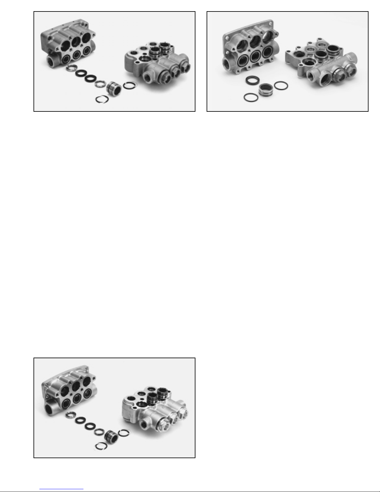
1530, 1531
V-Packing Arrangement
1540, 1540E
Hi-Pressure Seal Arrangement
REMOVING THE DISCHARGE MANIFOLD
1. Remove the HSH screws.
2. Support the manifold from the underside and tap the backside
of the discharge manifold with a soft mallet to gradually work
manifold from pump.
3. Remove the o-rings from lower chambers of the face of the
inlet manifold.
REMOVING THE INLET MANIFOLD
1. Remove the HSH Screws. Rotate the crankshaft to begin the
separation of the inlet manifold from the crankcase.
2. Support the manifold from the underside and tap the rear of the
inlet manifold with a soft mallet to gradually work from pump.
NOTE: Two screwdrivers on opposite sides of the manifold
may be used to assist separation.
SERVICING THE SEALS
Disassembly
1. To service the seals and packings, it is necessary to remove
both the discharge and inlet manifolds. Follow disassembly
procedures for REMOVING THE DISCHARGE MANIFOLD
and REMOVING THE INLET MANIFOLD.
NOTE: On models 1530, 1531, 2510, 2511, the spacer with
coil springs may stay in the discharge manifold or inlet manifold. On models 1540, 1540E, the HPS spacer will generally
stay in the inlet manifold.
2. Models 1530, 1531, 2510, 2511: Remove the spacer with coil
springs from either manifold and exposed o-rings and backup-rings from the spacer.
2510, 2511
V-Packing Arrangement
Models 1540, 1540E, 1560: Remove the exposed o-ring.
Insert two screwdrivers into the grooves on opposite sides of
the spacer and pry from the chamber.
CAUTION: Exercise caution as the screwdrivers may score
o-ring sealing surface.
3. Models 1530, 1531, 2510, 2511: Remove male adapter, two
V-Packings and female adapter from each seal chamber.
Models 1540, 1540E: Remove Hi-Pressure seal (HPS) from
each seal chamber.
Model 1560: Remove three V-Packings and female adapter
from each seal chamber.
4. Place the inlet manifold on the work surface with crankcase
side up.
5. Models 1530, 1531, 1540, 1540E, 1560: Use a screwdriver to
remove Lo-Pressure seal (LPS) from backside of manifold.
Models 2510, 2511: Use a screwdriver to remove washer and
Lo-Pressure seal from backside of manifold.
CAUTION: Exercise caution as the screwdriver may score
o-ring sealing surface.
Reassembly
NOTE: For certain applications apply liquid gasket to the o-ring
crevices and seal surfaces. Refer to Tech Bulletin 053 for
model identification.
NOTE: EPDM elastomers require silicone-base lubricant.
NOTE: For standard applications, apply a small amount of oil
to the outside edge of the LPS, HPS, VP, MA, FA and o-rings
for ease of installation and to avoid damage.
1. Examine Lo-Pressure seals for wear to the internal ridges,
outer surfaces or for broken springs and replace as needed.
2. Press Lo-Pressure seal into each seal chamber of the Inlet
Manifold with the garter spring down.
Models 2510, 2511: Install washers into each seal chamber.
NOTE: When using alternate materials, the fit of the special
materials may be snug and require gently driving the LPS
into position with a cylinder of the same diameter to assure a
square seating and no damage to the LPS.
3. Models 1530, 1531, 2510, 2511: Examine the spacer with
coil springs for scale build-up, wear, broken or fatigued coil
springs and replace as needed. Examine both front and rear
o-rings and back-up-rings for cuts or deterioration, replace as
needed.
Models 1540, 1540E: Examine the HPS spacer for scale build-up
or wear and replace as needed. Examine the front and rear
o-rings for cuts or deterioration and replace as needed.
4. Models 1530, 1531, 2510, 2511: Examine male and female
adapters for wear and replace as needed.
Model 1560: Examine female adapter and spacer and replace
as needed.
 Loading...