

Page 1
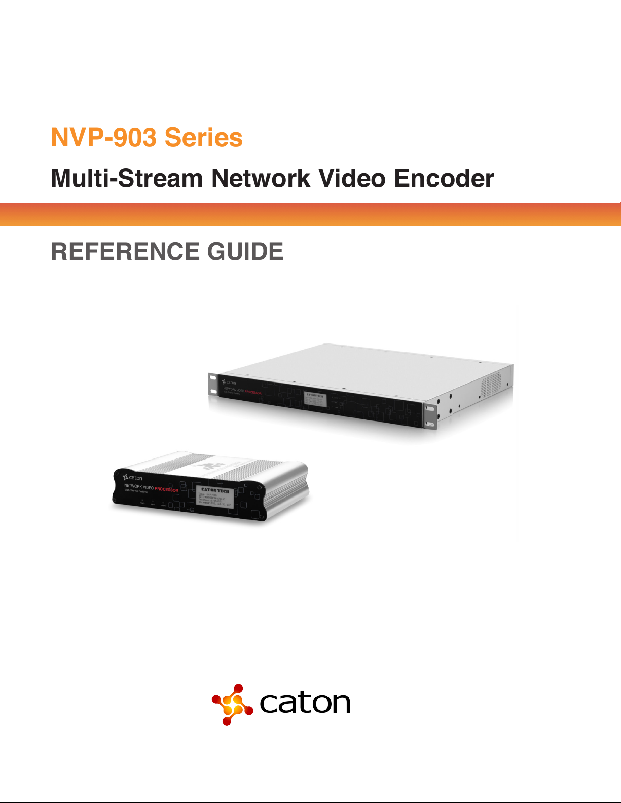
NVP-903 Series
Multi-Stream Network Video Encoder
REFERENCE GUIDE
Page 2

NVP-903 Series User Manual
Table of Contents
1 Introduction ......................................................................................................... 4
1.1 Product Overview ...................................................................................................... 4
1.2 Product Features ....................................................................................................... 4
2 Panel Design ........................................................................................................ 5
2.1 Front Panel ................................................................................................................. 5
2.1.2 NVP-903-R1 .......................................................................................................... 6
2.1.3 NVP-903-R2 .......................................................................................................... 7
2.2 Rear Panel .................................................................................................................. 8
3 Web Control [Encoder Mode] ........................................................................... 11
3.1 Log In ........................................................................................................................ 11
3.1.1 Log in via Ethernet .............................................................................................. 11
3.1.2 Log in via Wi-Fi .................................................................................................... 11
3.2 Configuration ........................................................................................................... 12
3.2.2 Streams ............................................................................................................... 14
3.2.3 Encoder Setting ................................................................................................... 18
Figure3.10 Encoder Setting .......................................................................................... 18
Click Apply to save the configuration. .......................................................................... 18
3.3 Advance .................................................................................................................... 21
3.3.1 Tools .................................................................................................................... 21
3.3.2 ETH Setting ......................................................................................................... 22
3.3.3 AP Information ..................................................................................................... 22
3.3.4 Login Information ................................................................................................. 23
3.3.5 Device Information .............................................................................................. 23
3.5 HD Stream Recording .............................................................................................. 25
3.6 Help Function ........................................................................................................... 26
4 Web Control [Decoder Mode] ........................................................................... 27
4.1 Log In ........................................................................................................................ 27
4.1.1 Log in via Ethernet .............................................................................................. 27
4.1.2 Log in via Wi-Fi .................................................................................................... 27
4.1.3 Work Mode .......................................................................................................... 28
4.2.1 Protocol ............................................................................................................... 29
Page 3

NVP-903 Series User Manual
4.2.2 Decoder ............................................................................................................... 31
4.3 Advance .................................................................................................................... 32
4.3.1 Tools .................................................................................................................... 32
4.3.2 ETH Setting ......................................................................................................... 33
4.3.3 AP Information ..................................................................................................... 34
4.3.4 Login Information ................................................................................................. 34
4.3.5 Device Information .............................................................................................. 34
5 Technical Specifications .................................................................................. 36
Page 4

NVP-903 Series User Manual
1 Introduction
1.1 Product Overview
NVP-903 are network video encoder and decoder series, which are specialized for high definition
real-time video streaming applications. It provides flexible streaming for low-bandwidth transmission
applications using H.264 video and AAC audio encoding, supporting FLV over RTMP streaming output,
thus seamlessly connecting to streaming media server. The third generation NVP series encoder –
NVP-903, support 3 encoding streams output for multi-screen application. Moreover, NVP-903
integrates H.264 decoding functions with HDMI output, to form a versatile media delivery solution over
IP network.
Integrated with Caton leading R2TP technology, NVP-903 and NVP decoders can also realize
high quality live video contribution and distribution over Open Internet.
1.2 Product Features
• Support [email protected] FULL-HD H.264 encoding/decoding
• Support HD-SDI, HDMI, Analog AV for video & audio input
• Support 1 channel encoding with 3 encoding streams output, with different bit rate/resolution for
multi-screen application
• Support two channel video & audio input and encoding independently (NVP-903-R2 only)
• Support RTMP PUSH, TS over HTTP, TS over UDP IP output, seamlessly connecting to
streaming media server
• Support high bit rate file recording into SD card
• Integrated with H.264 decoding function with HDMI output
• Support Caton proprietary R2TP protocol for contribution and distribution over Open Internet
• Internal hot-spot, support web UI control via PC/Android/iOS
• Web control language can switch between Chinese and English
4
Page 5
NVP-903 Series User Manual
2 Panel Design
2.1 Front Panel
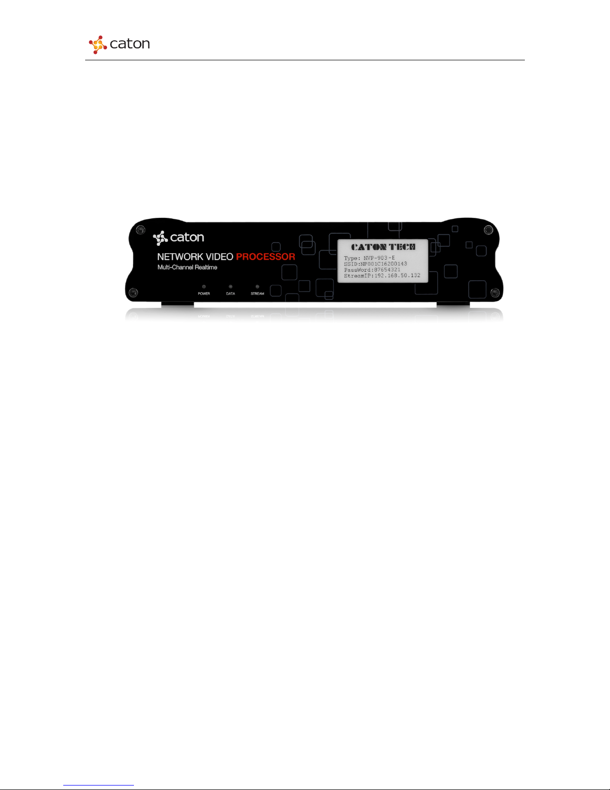
2.1.1 NVP-903
Compact design: 200.0 x 44.5 x 153.0mm, 900g
Figure2.1.1 NVP-903 Front Panel
NVP-903 Front Panel consists of an E Ink screen and 3 indicators: Power, Data and Stream.
Ø E Ink: Displays device basic info.
The info in E Ink will not be vanished after powered down.
n Work Mode: Current device work mode: NVP-903-E (Encoder Mode) or NVP-903-D
(Decoder Mode)
n SSID: Device serial number / SSID of NVP-903 internal hot-spot(AP)
n Password: Password of NVP-903 internal hot-spot(AP)
n Stream IP: Device IP address for streaming and web control
n Indicators: Displays current running status
n Power: [Blue] Device is powered up now
n Data: [Green] Device recognizes the input source successfully. [Red] Device does not
recognize the input source now
n Stream: [Green] Device is connected to target server/decoder and pushing/pulling
stream to it; [Red] Device is not pushing/pulling stream to target server/decoder.
5
Page 6
NVP-903 Series User Manual
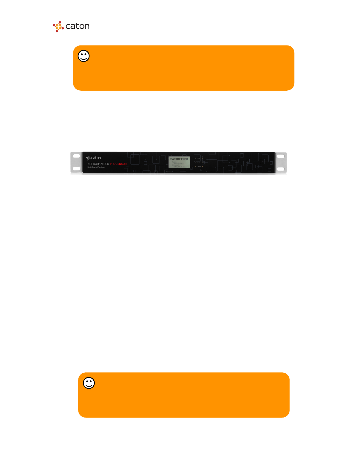
2.1.2 NVP-903-R1
1RU Frame Structure: 428.0 x 42.0 x 350.0mm4.0kg
Figure2.1.2 NVP-903-R1 Front Panel
NVP-903-R1 Front Panel consists of an E Ink screen and 3 indicators: Power, Data and Stream.
n E Ink: Displays device basic info. The info in E Ink will not be vanished after powered down.
n Work Mode: Current device work mode: NVP-903-R1-E (Encoder Mode) or NVP-903-R1-D
(Decoder Mode)
n SSID: Device serial number / SSID of NVP-903-R1 internal hot-spot(AP)
n Password: Password of NVP-903-R1 internal hot-spot(AP)
n Stream IP: Device IP address for streaming and web control
n Indicators: Displays current running status
n Power: [Blue] Device is powered up now
n Data: [Green] Device recognizes the input source successfully. [Red] Device does not
recognize the input source now
n Stream: [Green] Device is connected to target server/decoder and pushing/pulling stream to
it; [Red] Device is not pushing/pulling stream to target server/decoder.
Tips:
If Data indicators keep red when you have plugged in the video source, check
video/audio input settings via web control. Make sure the video/audio type in input setting and
the video source type to be the same.
Tips:
If Data indicators keep red when you have plugged in the video source, check
video/audio input setting via web control. Make sure the video/audio type in input setting
and the video source type to be the same.
6
Page 7

NVP-903 Series User Manual
2.1.3 NVP-903-R2
1RU Frame Structure: 428.0 x 42.0 x 350.0mm4.0kg
Figure 2.1.3 NVP-903-R2 Front Panel
NVP-903-R2 Two encoder information is displayed on the same E Ink screen; each corresponds
to three indicator light.
n E Ink: Displays device basic info. The info in E Ink will not be vanished after powered
down.
n CH1-TYPE: First encoder current work mode: NVP-903-R-E (Encoder Mode) or NVP-
903-R-D (Decoder Mode)
n CH2-TYPE: Second encoder current work mode: NVP-903-R-E (Encoder Mode) or
NVP-903-R-D (Decoder Mode)
n CH1-IP: IP address for the first encoder
n CH2-IP: IP address for the second encoder
n Indicators: Displays current running status
n Power: [Blue] Device is powered up now
n Data: [Green] Device recognizes the input source successfully. [Red] Device does
not recognize the input source now
n Stream: [Green] Device is connected to target server/decoder and pushing/pulling
stream to it; [Red] Device is not pushing/pulling stream to target server/decoder.
Tips:
If Data indicators keep red when you have plugged in the video source, check
video/audio input setting via web control. Make sure the video/audio type in input setting
and the video source type to be the same.
7
Page 8

NVP-903 Series User Manual
2.2 Rear Panel
2.2.1 NVP-903
Figure2.2.1 NVP-903 Rear Panel
NVP-903 Rear Panel consists of power interface, video/audio interface, network interface and SD
card slot.
n Power: Connect NVP-903 power adapter to power up the device
n SDI:
n Encoder Mode: HD/SD-SDI video/audio source input
n Video:
n Encoder Mode: Analog video source input
n Audio (L&R):
n Encoder Mode: Analog audio source input
n HDMI IN:
n Encoder Mode: HDMI video/audio source input
n HDMI OUT:
n Encoder Mode: HDMI video/audio source loop-out
n Decoder Mode: HDMI video/audio output
n ETH: Network interface for streaming and device web control
n USB: USB2.0 for Wi-Fi dongle function (In developing)
n SD Card: Insert SD card for video recording (In developing)
8
Page 9
NVP-903 Series User Manual
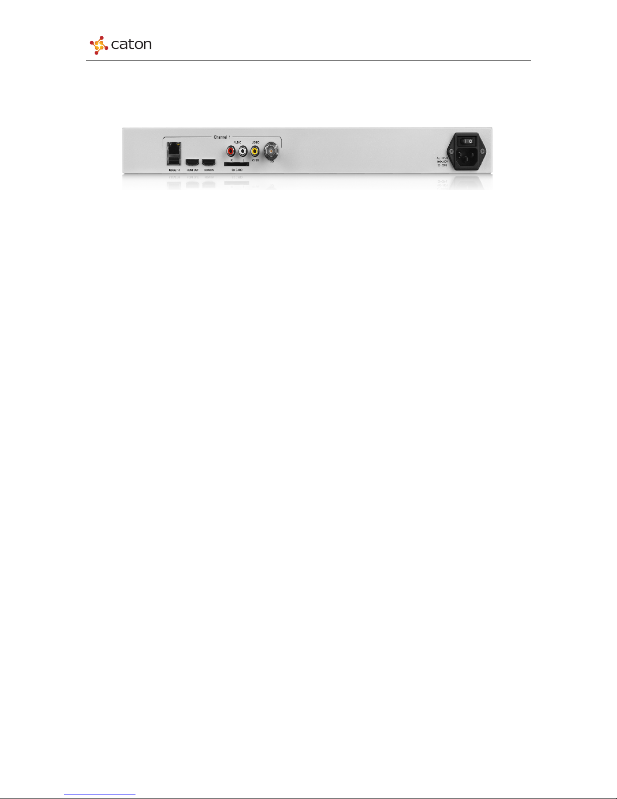
2.2.2 NVP-903-R1
Figure2.2 NVP-903-R1 Rear Panel
NVP-903-R1 Rear Panel consists of power interface, video/audio interface, network interface and
SD card slot.
n Power: Connect NVP-903-R1 power line to power up the device
n SDI:
n Encoder Mode: HD/SD-SDI video/audio source input
n Video:
n Encoder Mode: Analog video source input
n Audio (L&R):
n Encoder Mode: Analog audio source input
n HDMI IN:
n Encoder Mode: HDMI video/audio source input
n HDMI OUT:
n Encoder Mode: HDMI video/audio source loop-out
n Decoder Mode: HDMI video/audio output
n ETH: Network interface for streaming and device web control
n USB: USB2.0 for Wi-Fi dongle function (In developing)
n SD Card: Insert SD card for video recording (In developing)
9
Page 10
NVP-903 Series User Manual
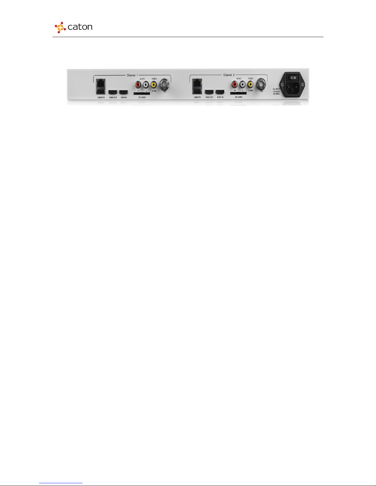
2.2.3 NVP-903-R2
Figure2.2.3 NVP-903 Rear Panel
NVP-903-R2 Two encoder each correspondent to power interface, video/audio interface, network
interface and SD card slot.
n Power: Connect NVP-903-R2 power adapter to power up the device
n SDI:
n Encoder Mode: HD/SD-SDI video/audio source input (Decoder mode can not output
HD/SD-SDI video/audio source)
n Video:
n Encoder Mode: Analog video source input
n Audio (L&R):
n Encoder Mode: Analog audio source input
n HDMI IN:
n Encoder Mode: HDMI video/audio source input
n HDMI OUT:
n Encoder Mode: HDMI video/audio source loop-out
n Decoder Mode: HDMI video/audio output
n ETH: Network interface for streaming and device web control
n USB: USB2.0 for Wi-Fi dongle function (In developing)
n SD Card: Insert SD card for video recording
10
Page 11
NVP-903 Series User Manual
3 Web Control [Encoder Mode]
3.1 Log In
NVP-903 series support PC web control via Ethernet port, it also supports PC/Smartphone/Pad
wireless web control via NVP-903 internal hotspot.
NVP-903-R2 has two encoders, each needs to be carried out on the website login and setting
separately. Refer to the IP address display on the front panel E Ink screen to login and set up
individually.
3.1.1 Log in via Ethernet
1) Prepare a computer with Ethernet port and Internet web browser.
2) Connect your PC to the NVP-903 ETH port via Ethernet.
3) Configure computer IP address, make sure that NVP-903 and the computer IP are in the
same network segment
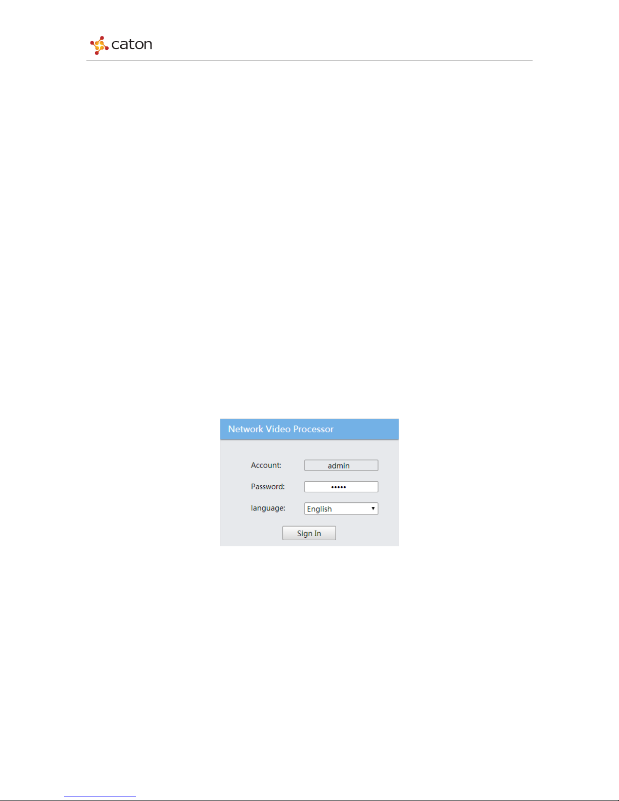
4) Input the device IP address in the web browser, it will displays the Log in page, as follows:
(Default IP Address: 202.0.0.138)
Figure3.1 Log in
5) Type in the Account and Password to login.
(Default Account: admin; Default Password: admin)
3.1.2 Log in via Wi-Fi
1) Prepare a PC/Pad/Smartphone with Wi-Fi function and Internet web browser.
2) Search Wi-Fi SSID of NVP-903 internal hotspot(AP) and connect your PC/Pad/Smartphone
to it. (Default AP Password: 87654321)
11
Page 12

NVP-903 Series User Manual
3) Input the device IP address in the web browser, it will displays the Log in page, as in Figure
3.1
4) Type in the Account and Password to login.
(Default Account: admin; Default Password: admin)
3.2 Configuration
Click Configuration in main menu to enter the basic setting page, as follows:
Figure3.2 Configuration
In Configuration page, users can configure basic settings of video/audio source, transport
protocol and device IP setting.
TIPS;
SSID of NVP-903 internal hotspot (AP) will be displayed in the E-Ink of device
front panel.
12
Page 13

NVP-903 Series User Manual
Click Apply to save the configuration.
3.2.1 Interface
Select the video/audio source type to encode and the transport protocol for streaming.
Figure3.3 Interface
Ø Video:
n Video Input: Video type of video source setting
n Active: Video source status. ON: Device has recognized this type of
video source; OFF: Device has not recognized this type of video source
n Input Format: Format of video input source.
Ø Audio:
n Audio Input: Audio type of audio source setting
n Active: Audio source status. ON: Device has recognized this type of audio source; OFF:
Device has not recognized this type of audio source
n Sample Freq(HZ): Sampling rate of audio input source.
13
Page 14

NVP-903 Series User Manual
Table3-1 Interface
Menu Name
Range
Interface
Video Input Source
SDI
HDMI
CVBS
ColorBar (Internal Source)
BlackField (Internal Source)
Audio Input Source
SDI-Ch1/2
SDI-Ch3/4
SDI-Ch5/6
SDI-Ch7/8
HDMI
Analog
1KHz (Internal Source)
Silence (Internal Source)
Transport Protocol
R2TP
R2TP-S
UDP
HTTP (TS over HTTP)
RTMP (RTMP Push)
3.2.2 Streams
NVP-903 support 1 channel video/audio source input with 3 channel encoding streams output. The
encoding streams can be configured with different target address.
Ø Transport Protocol: Current transport protocol for 3 encoding streams
n Transmitting: NVP-903-R2 is transmitting the stream to target device now, and it will display
realtime transmitting bit rate
n Connecting: NVP-903-R2 is trying to connect to target device now
n Disconnected: NVP-903-R2 does not transmit the stream to target device.
14
Page 15
NVP-903 Series User Manual
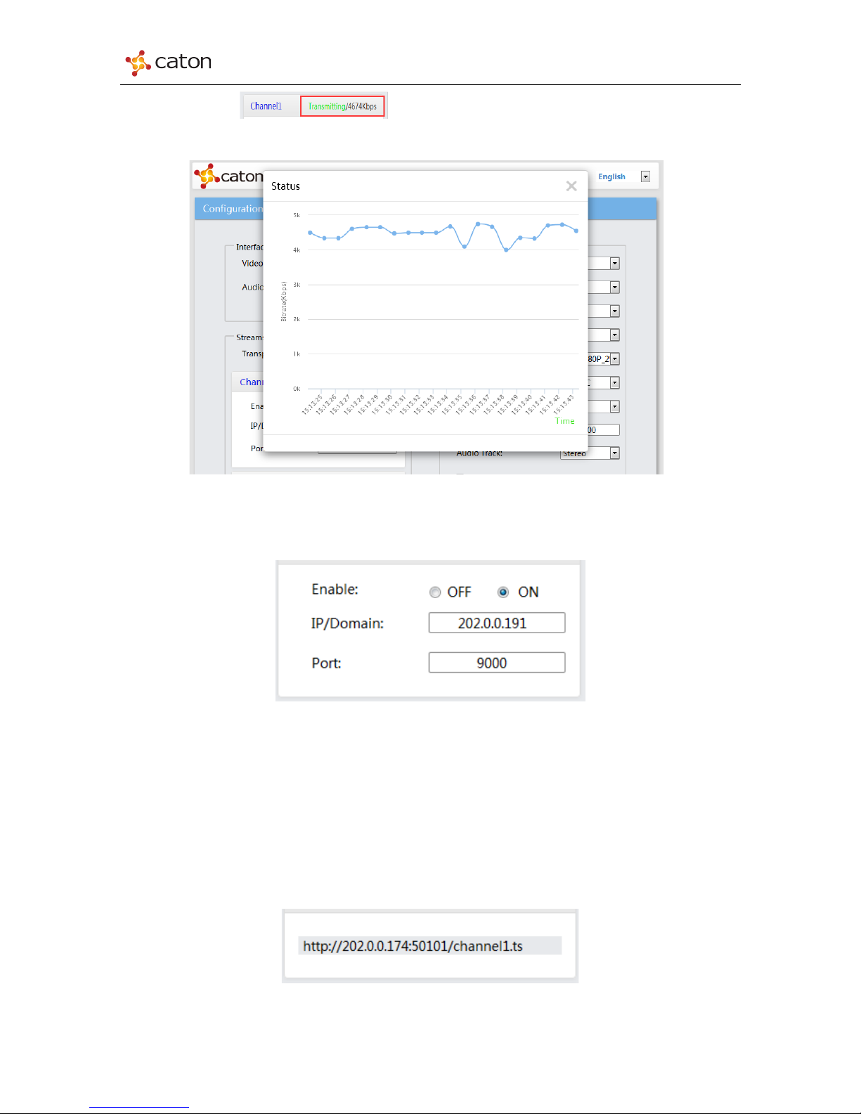
Click Transmitting the real time stream graph will pop up as the
picture shown below:
Figure3.4 Real time Stream graph
1) UDP
Figure3.5 UDP
n Enable: Enable current encoding streams to transmit. ON: Enable the transmitting;
OFF: Disable the transmitting
n Port: Transport port for UDP transmission. Range: 1024~65535
n IP Address: IP address of target device to receive UDP streams.
2) HTTP (TS over HTTP)
Figure3.6 HTTP
15
Page 16
NVP-903 Series User Manual
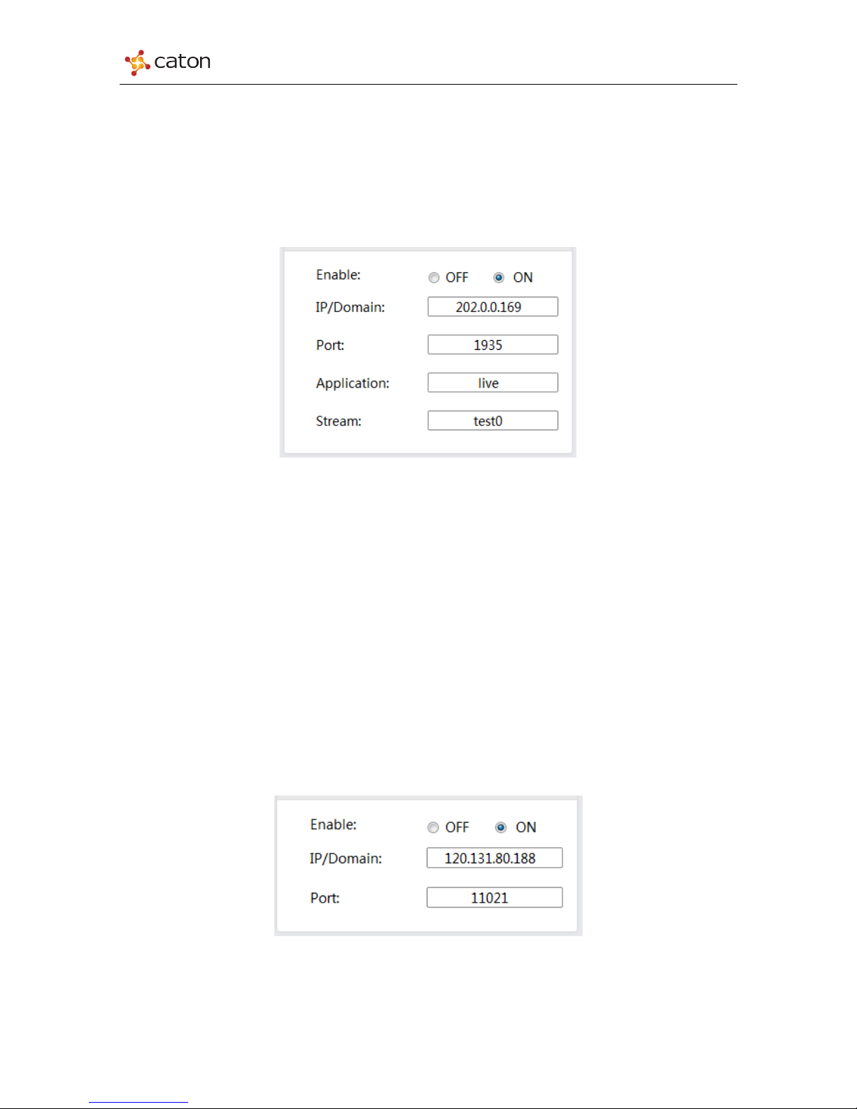
For HTTP transmission, NVP-903 series will generate a stream URL for each encoding channel (e.g.
http://202.0.0.139:50101/channel1.ts). Configure target decoder/server with this stream URL to pull
the stream for NVP-903.
3) RTMP
Figure3.7 RTMP
For RTMP transmission, the stream URL is generated by target RTMP streaming server.
Configure NVP-903 with this stream URL to push the stream to RTMP streaming server.
n Enable: Enable current encoding streams to transmit. ON: Enable the transmitting;
OFF: Disable the transmitting
n Port: Transport port for RTMP transmission. Default: 1935
n IP Address: IP address of target RTMP streaming server
n Application: The Application info in the stream URL
n Stream: The Stream ID in the stream URL
4) R2TP
Figure3.8 R2TP
n Enable: Enable current encoding streams to transmit. ON: Enable the transmitting;
OFF: Disable the transmitting
16
Page 17
NVP-903 Series User Manual
n Port: Transport port for R2TP transmission. Range: 1024~65535. Please make sure
R2TP port of NVP-903 and target decoder device to be the same.
n IP Address: IP address of target decoder device.
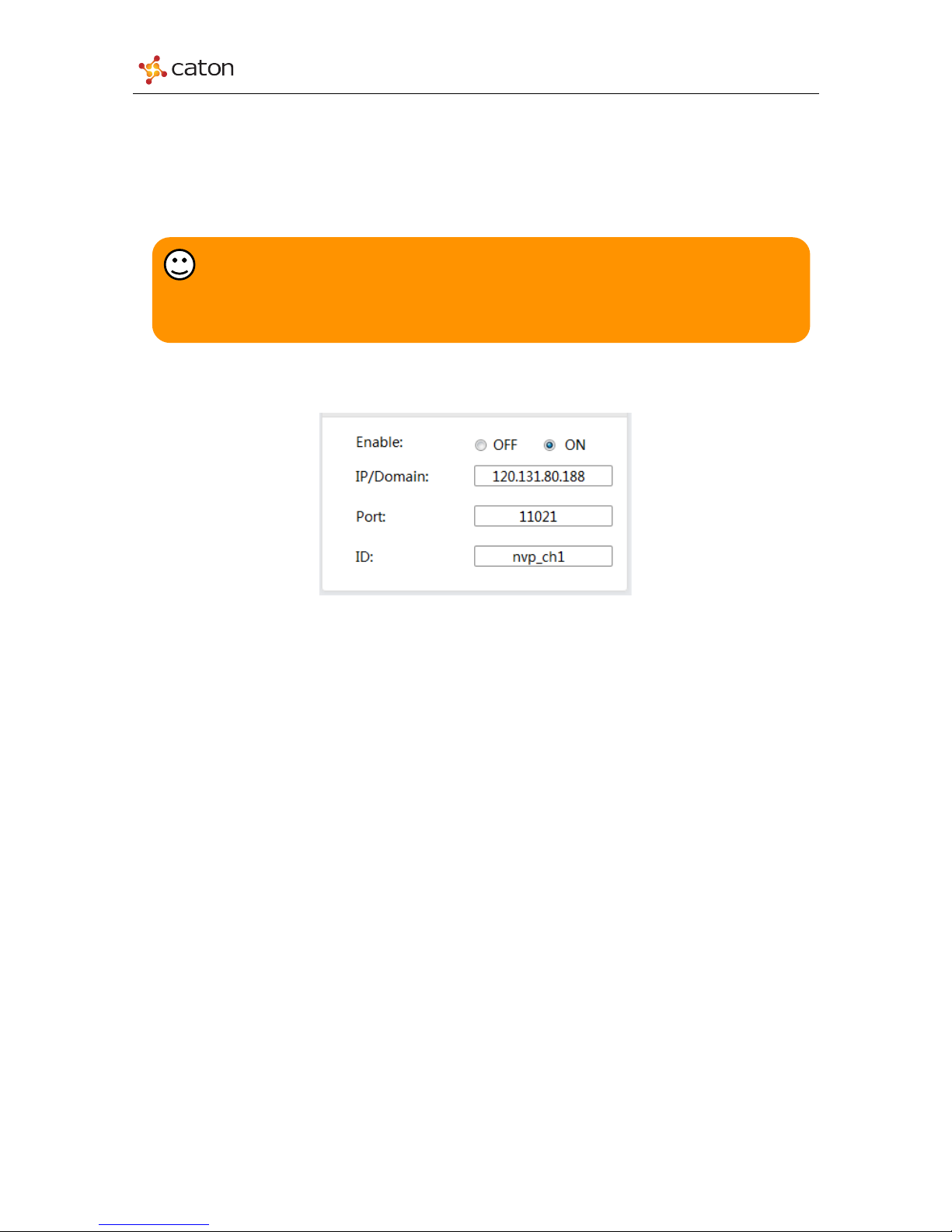
5) R2TP-S
Figure3.9 R2TP-S
n Enable: Enable current encoding streams to transmit. ON: Enable the transmitting;
OFF: Disable the transmitting
n Port: Transport port for R2TP-S transmission. The R2TP-S port is provided by target
R2TP Relay Server
n IP Address: IP address of target R2TP Relay Server
n ID: Transport ID for R2TP-S transmission. The transport ID is provided by target R2TP
Relay Server
Tips:
R2TP is the proprietary transport protocol of Caton Technology. For R2TP
transmission, please make sure the decoder device support R2TP protocol.
17
Page 18
NVP-903 Series User Manual
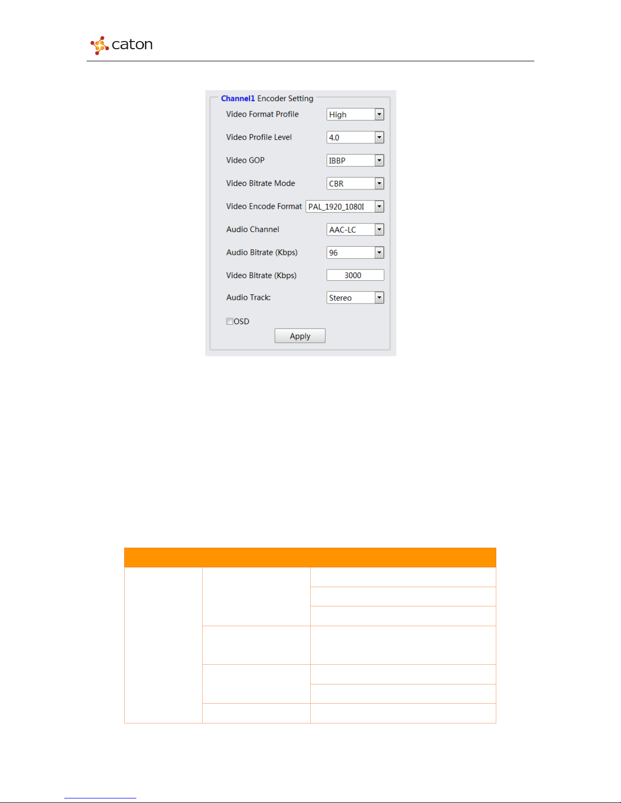
3.2.3 Encoder Setting
Figure3.10 Encoder Setting
In the encoder setting page, user can configure the encode settings of 3 encoding streams
separately.
Click Channel1/Channel2/Channel3 column to select the encoding channel.
Click Apply to save the configuration.
Table 3-2 Encoder Setting
Menu Name
Advance
Video Compress Profile
High
Main
Baseline
Video Compress Level
1.1/1.3/2.0/2.1/2.2/2.3/3.0/3.1/3.2/4.0/4.1/4.2
Video GOP
IP
IBBP
Video Bitrate Mode
CBR
18
Page 19

NVP-903 Series User Manual
VBR
Video Encode Format
PAL
1920*1080P (Only Channel1)
1920*1080P_25Hz
1920*1080I
1440*1080P
1440*1080I
960*1080I
1280*720P
1280*720P_25Hz
720*576P
720*576I
720*576P_25Hz
640*360P
352*288P
NTSC
1920*1080P (Only Channel1)
1920*1080P_29.97Hz
1920*1080I
1440*1080P
1440*1080I
960*1080I
1280*720P
1280*720P_29.97Hz
720*480P
720*480I
720*480P_29.97Hz
640*360P
352*240P
Video Bitrate (Kbps)
CBR
HD: 650-8000Kbps
SD: 300-8000Kbps
VBR
HD: 650-4000Kbps
SD: 300-4000Kbps
Audio Compress STD
AAC-LC
AAC-HE
MPEG1-Layer2
19
Page 20

NVP-903 Series User Manual
Audio Track
Stereo
Monaural
DualMono
Audio Bitrate (Kbps)
AAC-LC
96
128
192
256
384
512
AAC-HE
48
64
MPEG1-Layer2
128
192
256
For OSD setting, please refer to Chapter 3.4 OSD in this manual.
Tips:
1. For Video Encoder Format, Channel 1 support up to
1920*1080P_59.94/50Hz, Channel 2 & Channel 3 support up to
1920*1080P_29.97/25Hz.
2. NVP-903 support encoding format up-scaler and down-scaler, however it
cannot transform the frequency between PAL and NTSC.
20
Page 21
NVP-903 Series User Manual
3.3 Advance
3.3.1 Tools
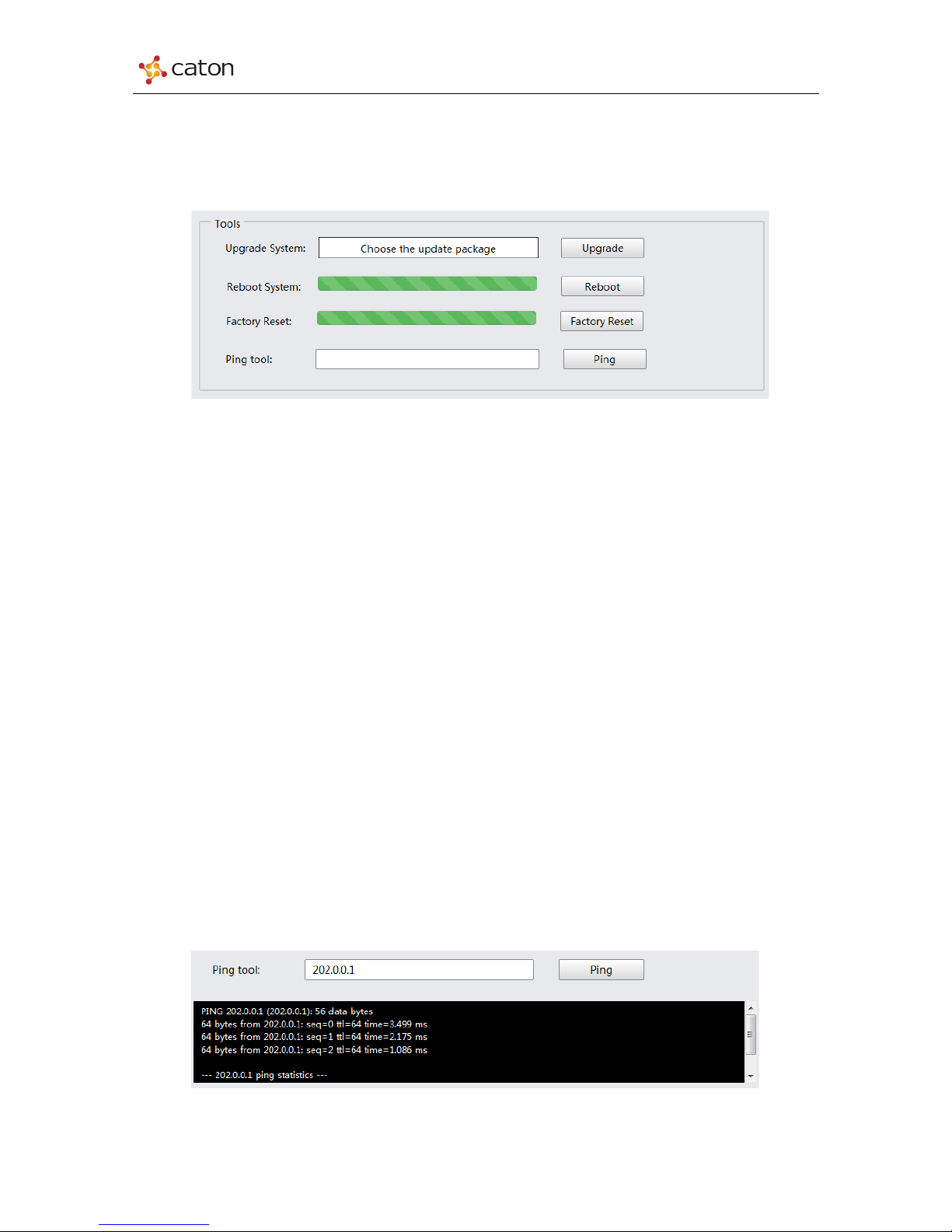
In Tools column, user can upgrade or reboot the device, reset device to default setting.
Figure3.11 Tools
1) Upgrade System
Click Choose the update package to select the upgrade package in PC, and click
Upgrade to upgrade. The upgrade process will need about 2 minutes, and device will reboot
automatically.
2) Reboot System
Click Reboot to reboot the device. The reboot process will need about 1 minute.
3) Factory Reset
Click Factory Reset to recover to the default settings. The reset process will need about 2
minutes, and device will reboot automatically.
4) Ping
Use the ping tools to confirm the connection status between NVP-903 and target device. Type in
the target IP address and click Ping to get the result.
Figure3.12 Ping
21
Page 22
NVP-903 Series User Manual
3.3.2 ETH Setting
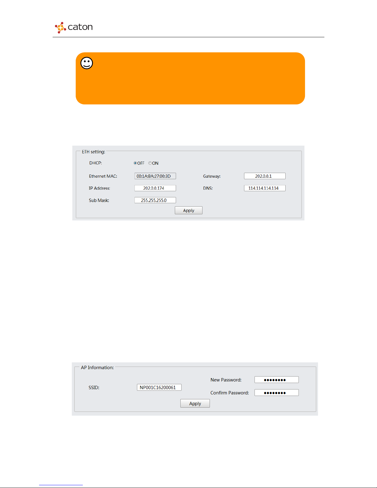
In ETH Setting column, user can configure device IP address.
Figure3.13 ETH Setting
n DHCP: Select IP setting mode. OFF: Manual mode; ON: DHCP mode
n Ethernet MAC: Device MAC address
n IP Address: Device IP address for video streaming and web control
n Sub Mask: Net mask of device IP setting
n Gateway: Gateway of device IP setting
n DNS: DNS server of device IP setting
Click Apply to save the configuration.
3.3.3 AP Information
In AP Information column, user can change the password of device AP.
Figure3.14 AP Information
Tips:
Please do not power up the device during upgrade or factory reset process.
The web Page will refresh automatically which means the process is already
finished.
22
Page 23
NVP-903 Series User Manual
Ø SSID: To view SSID of device AP. SSID of AP is the same as device serial number.
Ø New Password: To set new password of device AP. Default password: 87654321
Ø Confirm Password: To refill the new password to confirm.
Click Apply to save the configuration.
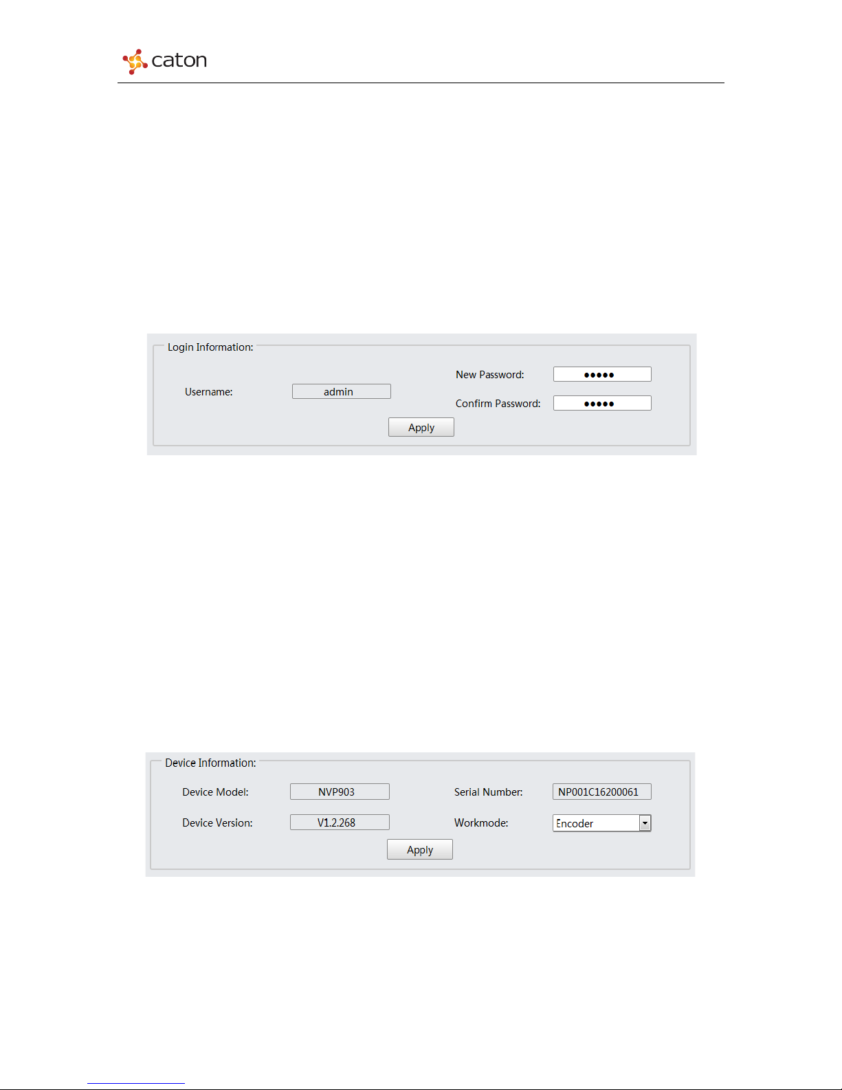
3.3.4 Login Information
In Login Information column, user can change the password for web log in.
Figure3.15 Login Information
Ø Username: To view account name to log in. Default: admin
Ø New Password: To set new password to log in. Default password: admin
Ø Confirm Password: To refill the new password to confirm.
Click Apply to save the configuration.
3.3.5 Device Information
In Device Information column, user can view device basic info or change the workmode.
Figure3.16 Device Information
Ø Device Model: To view device model name
Ø Device Version: To view device software & hardware version
Ø Serial Number: To view device serial number
23
Page 24
NVP-903 Series User Manual
Ø Workmode: To set the work mode of NVP-903: Encoder or Decoder
Click Apply to save the configuration.
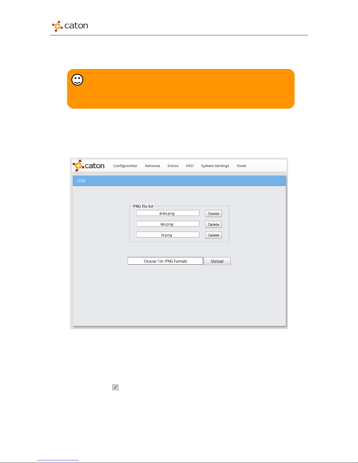
3.4 OSD
Click OSD in main menu to enter the OSD setting page, as follows:
Figure3.17 OSD
To use the picture file as OSD during encoding, you need to upload the png. file to the file
list in OSD page.
1) Click Choose File column to select png. file in your PC and click Upload to upload.
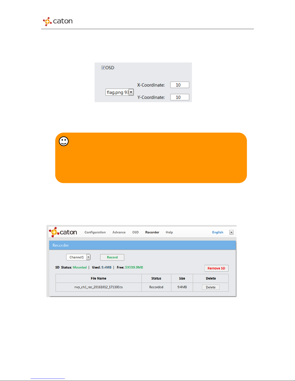
2) Click on O SD button in Advance page to use the png. file as OSD during
encoding. Select picture file name and set Coordinate X and Coordinate Y to configure the
Tips:
When the work mode of VBP-903 is changed, device will reboot automatically.
Encoder mode and Decoder mode cannot work in the same time.
24
Page 25
NVP-903 Series User Manual
position of OSD. (Left front corner is <0, 0>, OSD move to the right for 1 pixel as Coordinate X
add 1, and move to the bottom for 1 pixel as Coordinate Y add 1)
Figure3.18 X/Y-Coordinate
3) To delete picture file in the file list, click Delete.
3.5 HD Stream Recording
Click Recorder from the main menu to enter the Recorder setting page:
Figure3.19 Recorder Setting
Select Channel which you want to record, click Record to start.
Tips:
1. NVP-903 support uploading up to 3 picture files.
2. The picture format for OSD should be PNG.
3. The width pixel of the picture should be multiple to 128.
4. The picture size should be not exceeding the size of encoding format
25
Page 26
NVP-903 Series User Manual
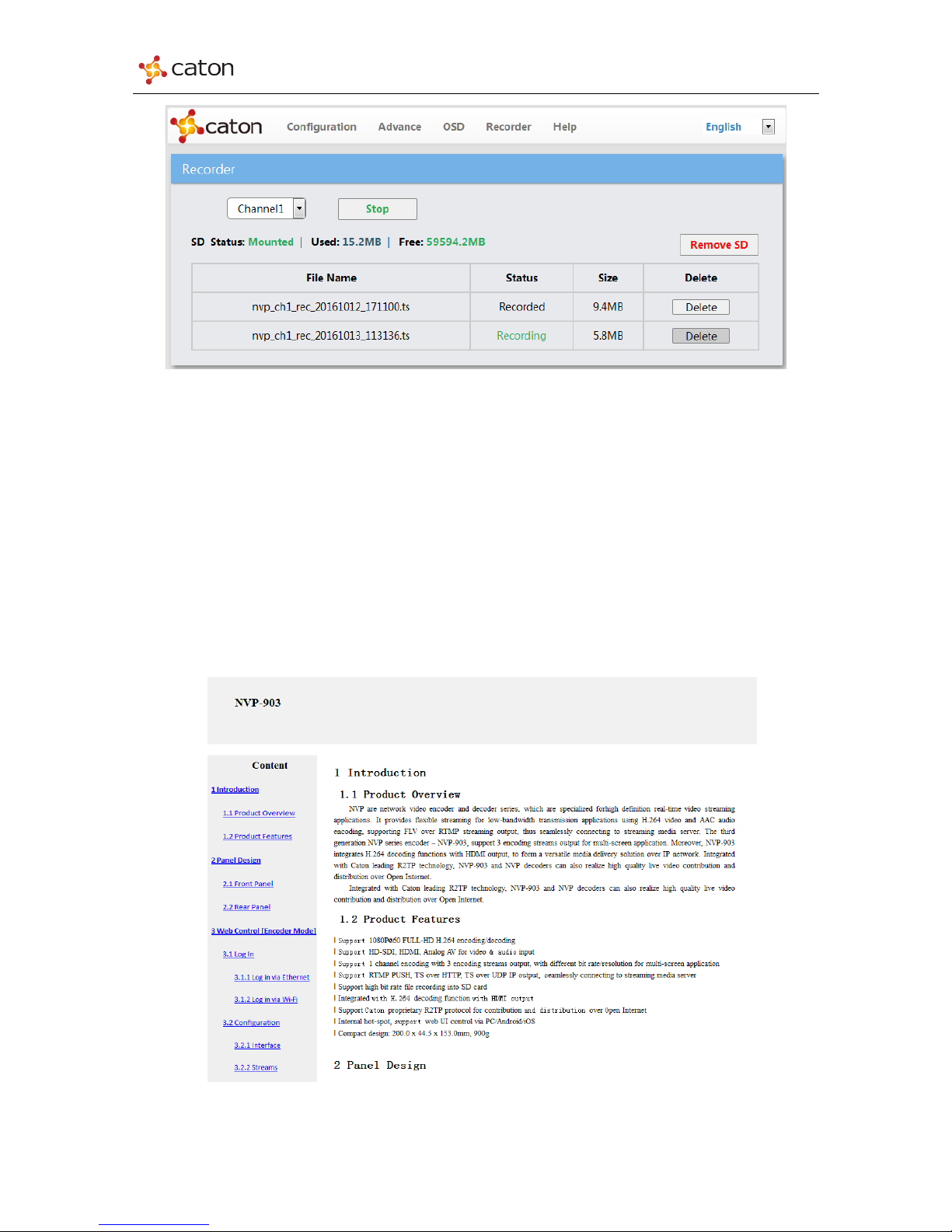
Figure3.20 Recorder Setting
Click Stop to stop recording. NVP903 supports single file recording up to 3 GB maximum, file that bigger
than 3GB will be saved in a new TS file. Click Delete to delete unwanted stream. Meanwhile, the used
and free space of SD card can be seen at the page. Click Remove SD to pull out the SD card from SD
card slot. Insert SD card to the computer to watch the recording stream.
3.6 Help Function
Click Help form the main menu to enter the help interface to see the device instructions
Figure3.21 Recorder Setting
26
Page 27
NVP-903 Series User Manual
4 Web Control [Decoder Mode]
4.1 Log In
NVP-903 supports PC web control via Ethernet port, it also supports PC/Smartphone/Pad
wireless web control via NVP-903 internal hotspot.
4.1.1 Log in via Ethernet
1) Prepare a computer with Ethernet port and Internet web browser.
2) Connect your PC to the NVP-903 ETH port via Ethernet.
3) Configure computer IP address, make sure that NVP-903 and the computer IP are in the
same network segment
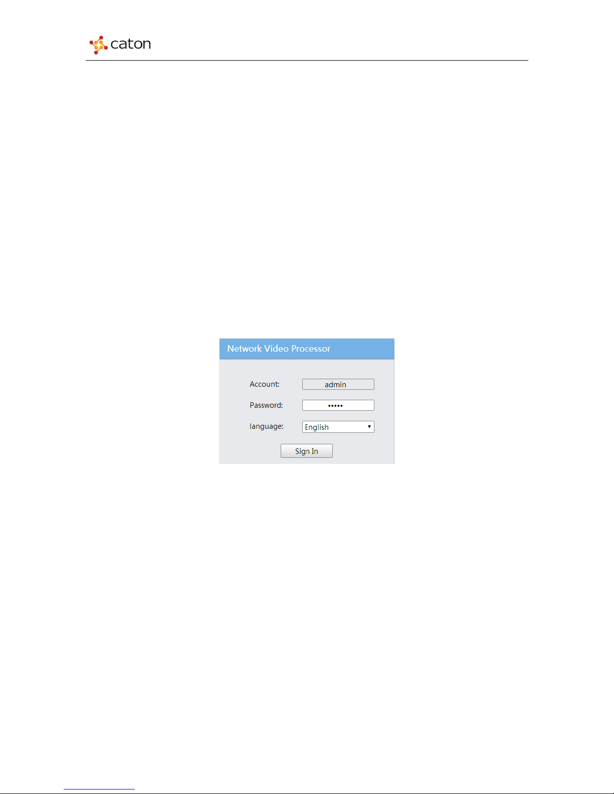
4) Input the device IP address in the web browser, it will displays the Log in page, as follows:
(Default IP Address: 202.0.0.138)
Figure4.1 Log in
5) Type in the Account and Password to login.
(Default Account: admin; Default Password: admin)
4.1.2 Log in via Wi-Fi
1) Prepare a PC/Pad/Smartphone with Wi-Fi function and Internet web browser.
2) Search Wi-Fi SSID of NVP-903 internal hotspot(AP) and connect your PC/Pad/Smartphone
to it. (Default AP Password: 87654321)
3) Input the device IP address in the web browser, it will displays the Log in page, as in Figure
4.1
4) Type in the Account and Password to login.
(Default Account: admin; Default Password: admin)
27
Page 28
NVP-903 Series User Manual
4.1.3 Work Mode
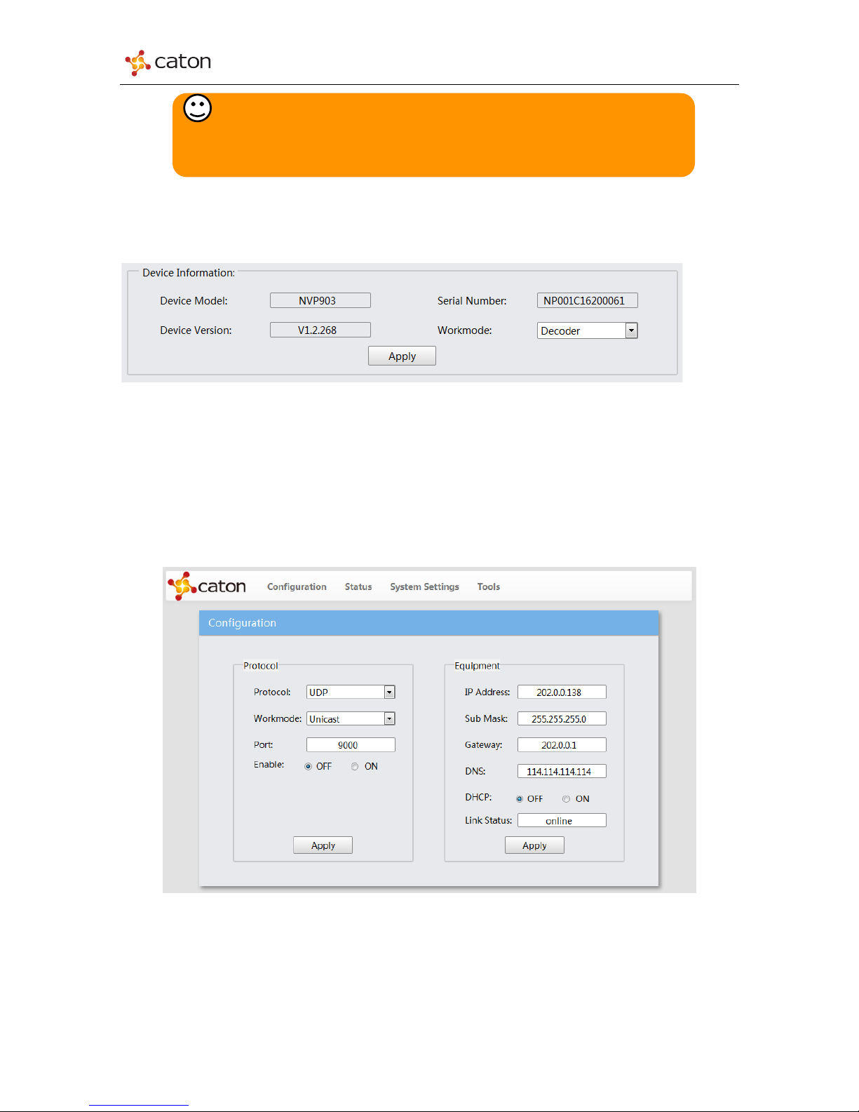
After log in, click System Settings in main menu to enter the system setting page.
Figure4.2 Work Mode
Confirm Workmode to be Decoder mode. Device will reboot automatically if the work mode
is changed.
4.2 Configuration
Click Configuration in main menu to enter the basic setting page, as follows:
Figure4.3 Configuration
In Configuration page, users can configure basic settings of transport protocol and device IP
setting.
Click Apply to save the configuration.
Tips:
SSID of NVP-903 internal hotspot (AP) will be displayed in the E-link of
device front panel.
28
Page 29
NVP-903 Series User Manual
4.2.1 Protocol
NVP-903 decoder mode support 1 channel STPS over IP decoding with HDMI output.
1) UDP Unicast
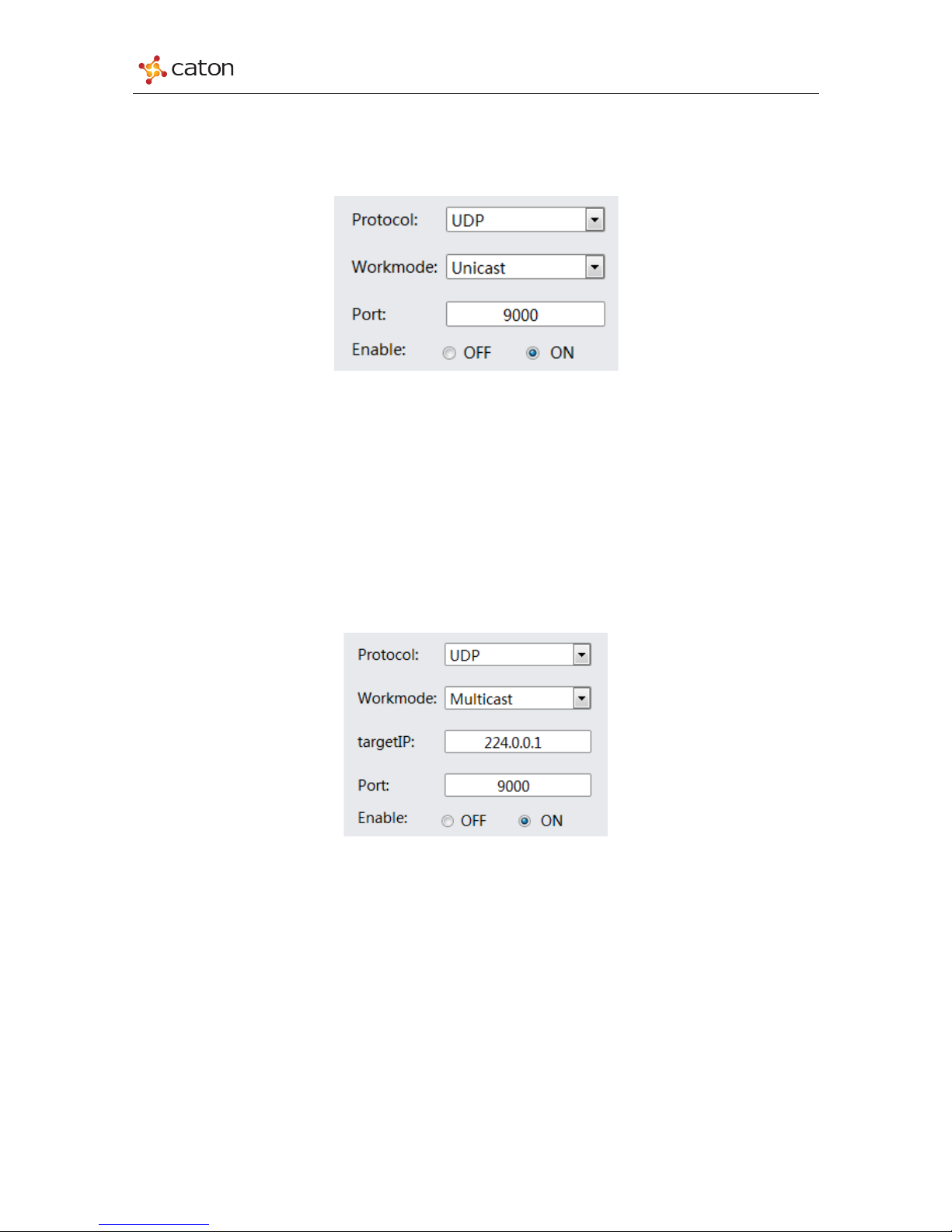
Figure4.4 UDP Unicast
n Protocol: Set Protocol to UDP
n Workmode: Set Workmode to Unicast
n Port: Transport port for UDP Unicast transmission. Range: 1024~65535
n Enable: Enable stream receiving. ON: Enable the receiving; OFF: Disable the
receiving
2) UDP Multicast
Figure4.5 UDP Multicast
n Protocol: Set Protocol to UDP
n Workmode: Set Workmode to Multicast
n Target IP: IP address for UDP Multicast transmission. Range: 224.0.0.0—
239.255.255.255
n Port: Transport port for UDP Multicast transmission. Range: 1024~65535
n Enable: Enable stream receiving. ON: Enable the receiving; OFF: Disable the
receiving
29
Page 30
NVP-903 Series User Manual
3) HTTP (TS over HTTP)
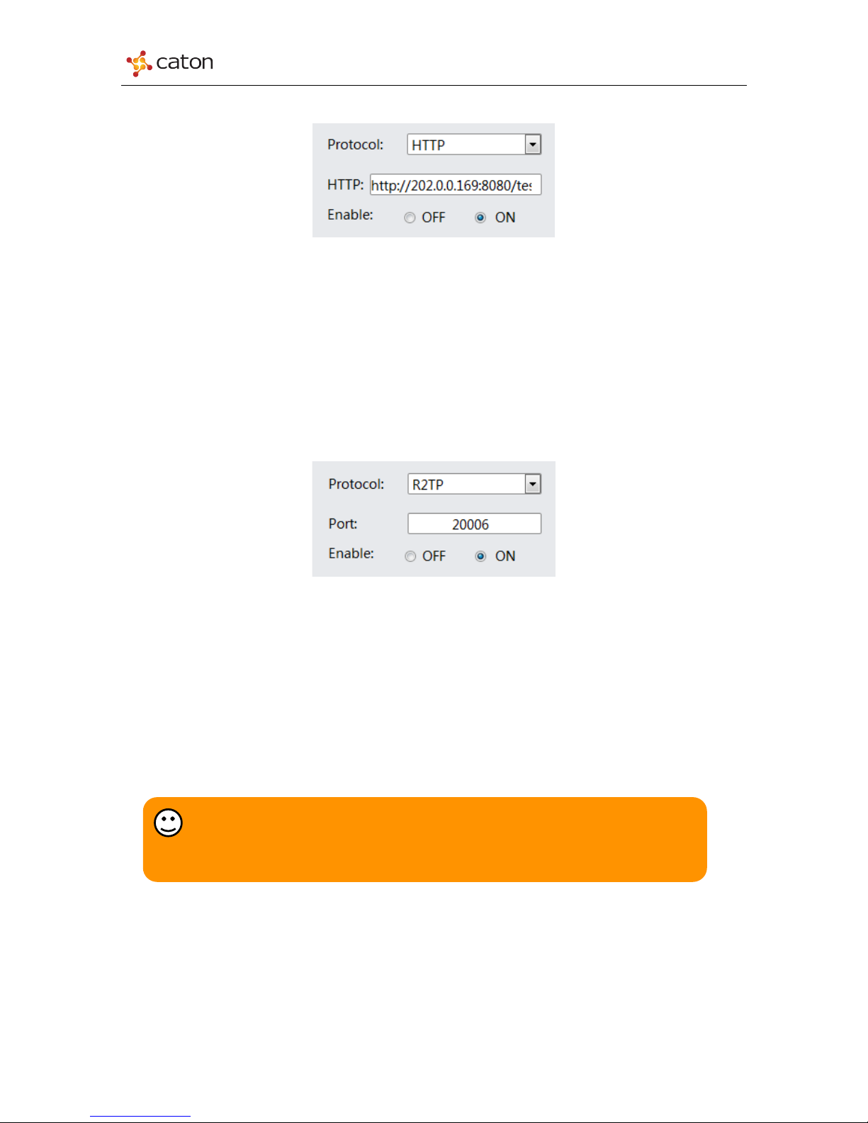
Figure4.6 HTTP
n Protocol: Set Protocol to HTTP
n HTTP: Type in HTTP stream URL that provided by encoder or streaming server
n Enable: Enable stream receiving. ON: Enable the receiving; OFF: Disable the
receiving
4) R2TP
Figure4.7 R2TP
n Protocol: Set Protocol to R2TP
n Port: Transport port for R2TP transmission. Range: 1024~65535. Please make sure
R2TP port of NVP-903 and target encoder device to be the same.
n Enable: Enable stream receiving. ON: Enable the receiving; OFF: Disable the
receiving
Tips:
R2TP is the proprietary transport protocol of Caton Technology. For R2TP
transmission, please make sure the encoder device support R2TP protocol.
30
Page 31
NVP-903 Series User Manual
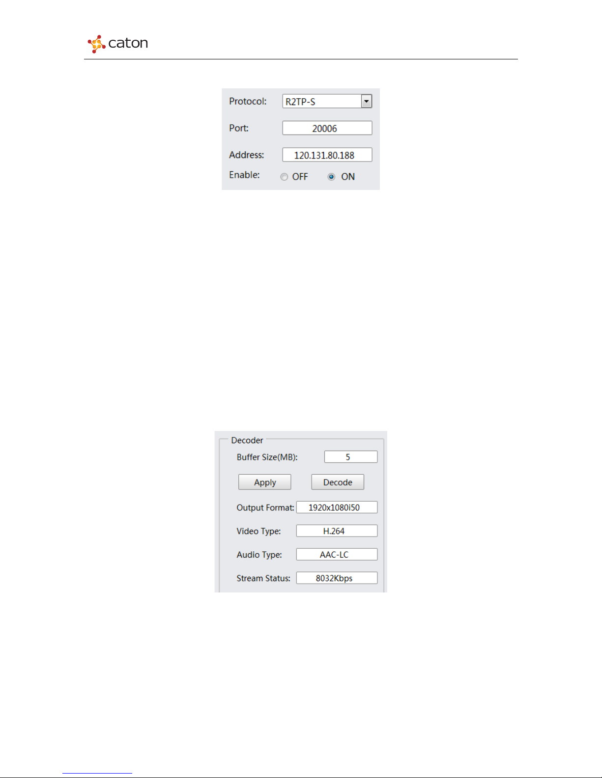
5) R2TP-S
Figure4.8 R2TP-S
n Protocol: Set Protocol to R2TP-S
n Port: Transport port for R2TP-S transmission. The R2TP-S port is provided by target
R2TP Relay Server
n IP Address: IP address of target R2TP Relay Server
n Enable: Enable stream receiving. ON: Enable the receiving; OFF: Disable the
receiving
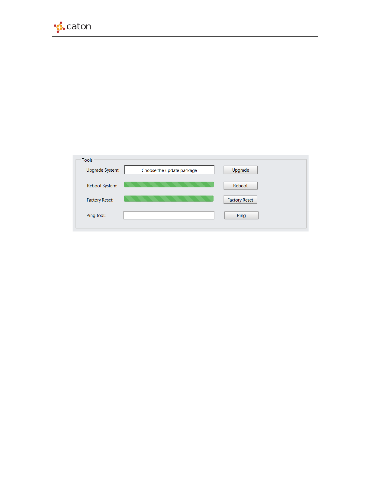
4.2.2 Decoder
In Decoder column, user can set decode buffer size, and view decode status.
Figure4.9 Decoder
n Buffer Size(MB): Set buffer size for video decoding. Range: 1~10MB
Click Apply to save the configuration
Click Decode to restart the decoding
n Output Format: The format of decoded video
31
Page 32
NVP-903 Series User Manual
n Video Type: Video compress format of input video source
n Audio Type: Audio compress format of input audio source
n Stream Status: Real-time bit rate of input IP stream.
4.3 Advance
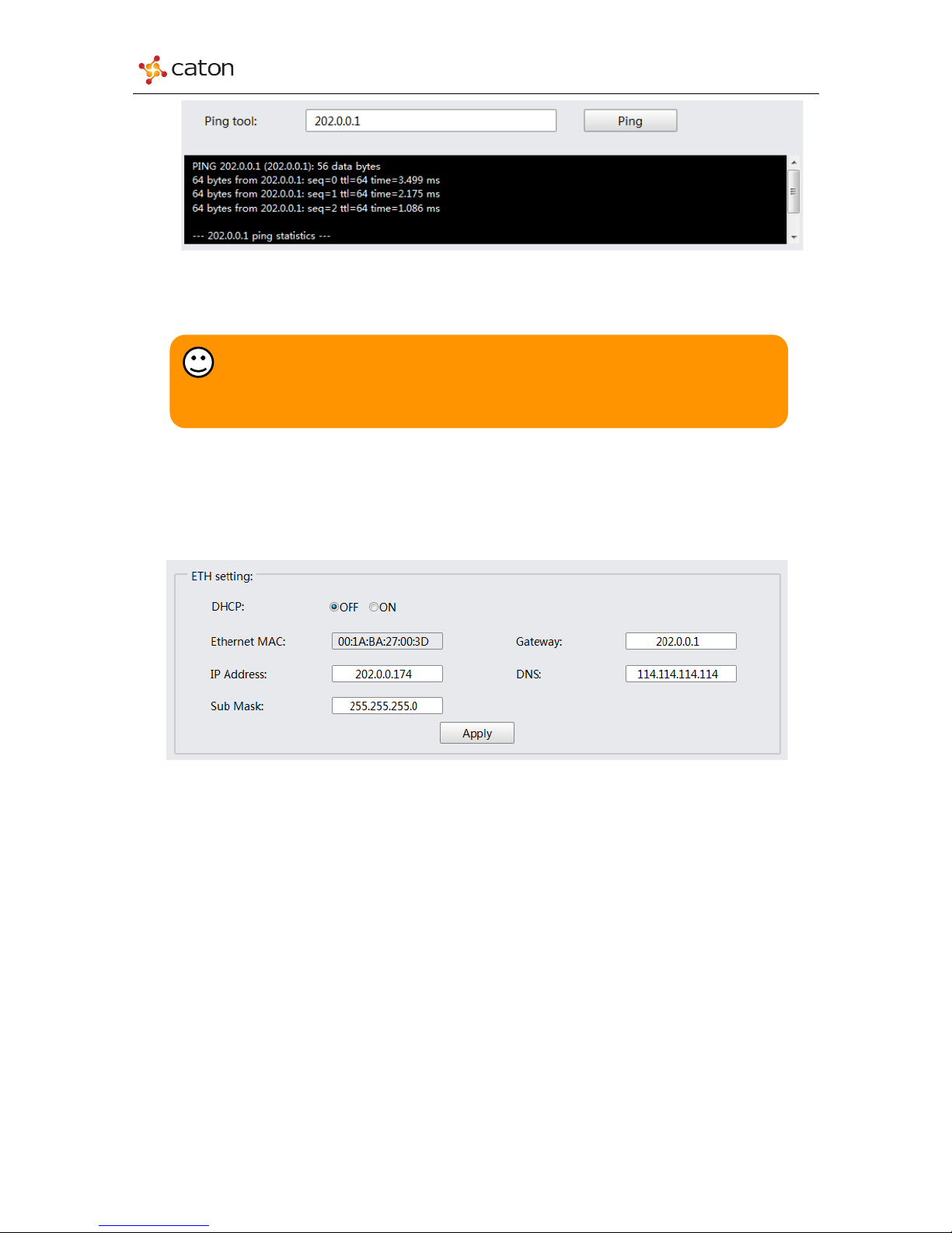
4.3.1 Tools
In Tools column, user can upgrade or reboot the device, reset device to default setting.
Figure4.10 Tools
1) Upgrade System
Click Choose the upgrade package to select the upgrade package in PC, and click Upgrade to
upgrade. The upgrade process will need about 2 minutes, and device will reboot automatically.
2) Reboot System
Click Reboot to reboot the device. The reboot process will need about 1 minute.
3) Factory Reset
Click Factory Reset to recover to the default settings. The reset process will need about
2 minutes, and device will reboot automatically.
4) Ping
Use the ping tools to confirm the connection status between NVP-903 and target device. Type
in the target IP address and click Ping to get the result.
32
Page 33
NVP-903 Series User Manual
Figure4.11 Ping
4.3.2 ETH Setting
In ETH Setting column, user can configure device IP address.
Figure4.12 ETH Setting
n DHCP: Select IP setting mode. OFF: Manual mode; ON: DHCP mode
n Ethernet MAC: Device MAC address
n IP Address: Device IP address for video streaming and web control
n Sub Mask: Net mask of device IP setting
n Gateway: Gateway of device IP setting
n DNS: DNS server of device IP setting
Click Apply to save the configuration.
Tips:
Please do not power off the device during the upgrade or factory reset process.
The web page will refresh automatically which means the process is already finished.
33
Page 34
NVP-903 Series User Manual
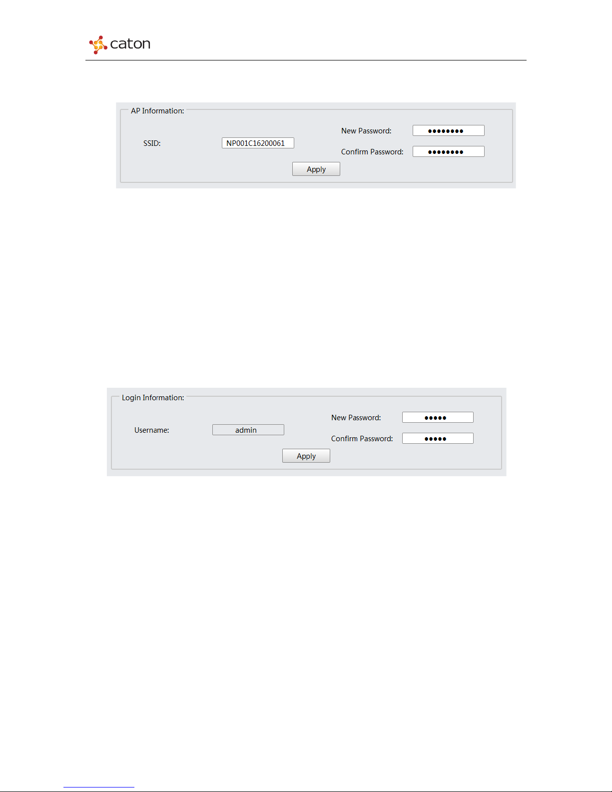
4.3.3 AP Information
In AP Information column, user can change the password of device AP.
Figure4.13 AP Information
Ø SSID: To view SSID of device AP. SSID of AP is the same as device serial number.
Ø New Password: To set new password of device AP. Default password: 87654321
Ø Confirm Password: To refill the new password to confirm.
Click Apply to save the configuration.
4.3.4 Login Information
In Login Information column, user can change the password for web log in.
Figure4.14 Login Information
Ø Username: To view account name to log in. Default: admin
Ø New Password: To set new password to log in. Default password: admin
Ø Confirm Password: To refill the new password to confirm.
Click Apply to save the configuration.
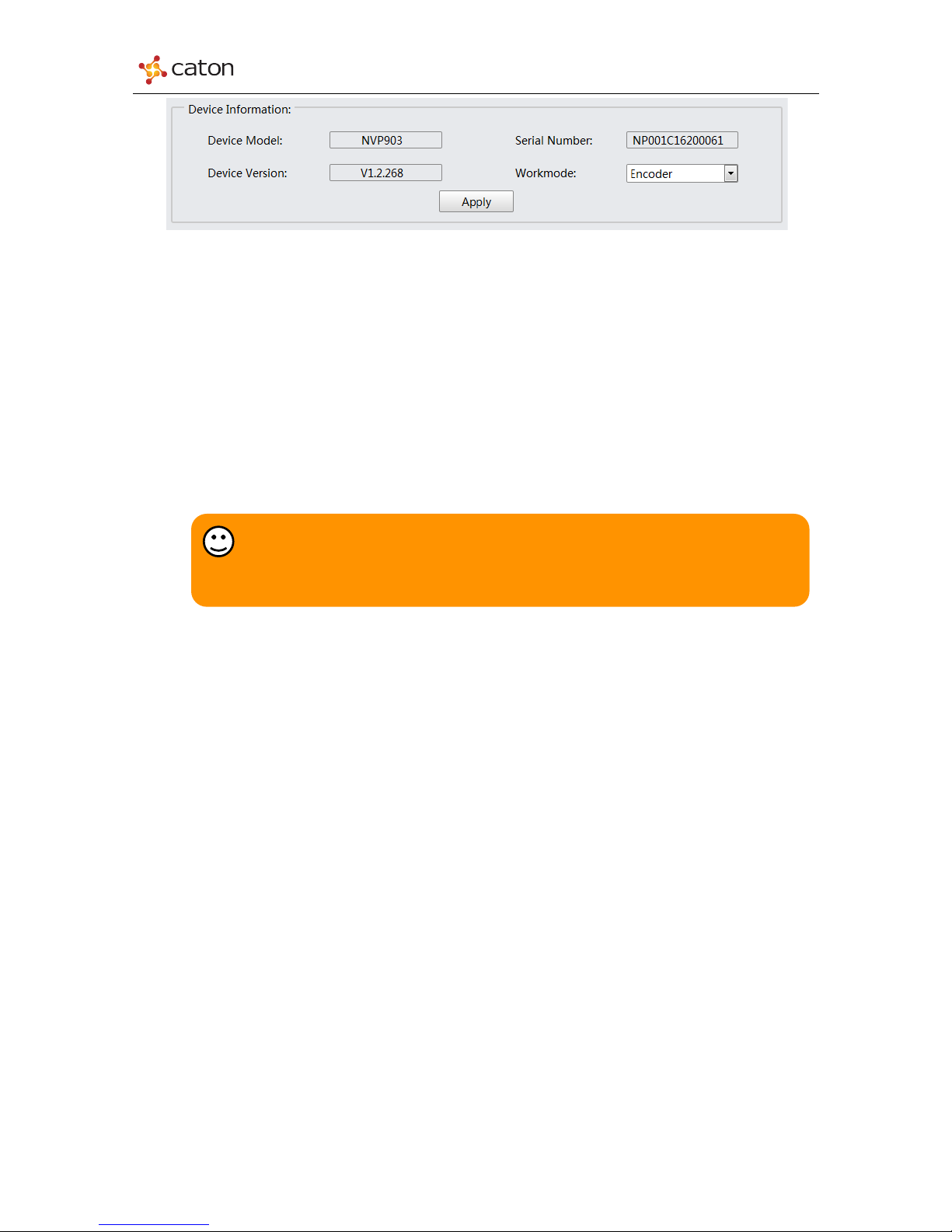
4.3.5 Device Information
In Device Information column, user can view device basic info or change the workmode.
34
Page 35
NVP-903 Series User Manual
Figure4.15 Device Information
Ø Device Model: To view device model name
Ø Device Version: To view device software & hardware version
Ø Serial Number: To view device serial number
Ø Workmode: To set the work mode of NVP-903: Encoder or Decoder
Click Apply to save the configuration.
Tips:
When the work mode of NVP-903 is changed, device will reboot automatically.
Encoder mode and Decoder mode cannot work in the same time.
35
Page 36

NVP-903 Series User Manual
5 Technical Specifications
[ENCODER MODE SPEC]
CODEC
Video Codec
H.264
GOP
IP/IBBP
Profile
BaseLine/Main/High
Bitrate Ctrl
CBR/VBR
Level
1.2/1.3/2.0/2.1/3.0/3.1/3.2/4.0/4.1/4.2
Bitrate
HD: 650Kbps-8Mbps
SD: 300Kbps-8Mbps
Bit Depth
8bit
Chroma
4:2:0
Multi-Stream
Up to 3 encoding streams
Input Format
1920x1080p59.94/50/29.97/25
1920x1080i59.94/50
1280x720p59.94/50
720x576i50, 720x480i59.94
Total Bitrate
≤20Mbps
Audio Codec
MPEG-1 Layer 2
AAC-LC
HE-AAC V1
Resolution
Up-Scalable & Down-Scalable
Audio Mode
Stereo/Dual Mono/Mono
OSD
PNG File for OSD
INPUT & OUTPUT
Video Inputs
HD-SDI *1, BNC, 75Ω
HDMI *1, V1.4a
Analog Video *1, RCA
IP Outputs
FLV over RTMP PUSH
TS over UDP
TS over HTTP
R2TP (License Need)
Audio Inputs
HD-SDI *1, BNC, 75Ω (Embedded)
HDMI *1, V1.4a (Embedded)
Analog Audio *2, RCA
Ethernet
RJ-45 *1(10/100/1000 BASE-T)
USB
USB2.0 *1
Video
Loop
HDMI Loop Out
SD Card
Standard SD Card Slot*1
PHYSICAL & MANAGEMENT
Management
Web-UI Control
Hotspot
Internal Wireless AP, 2.4GHz
Front Panel
E-Ink Info Display
Input Voltage
DC 12V
Dimensions
200.0 x 44.5 x 153.0mm (W x H x
D)
Weight
900g
[DECODER MODE SPEC]
CODEC
Video Codec
H.264: [email protected]/[email protected]
MPEG-2: MP@HL
Format
1920x1080p59.94/50/29.97/25
1920x1080i59.94/50/29.97/25
1280x720p59.94/50/29.97/25
720x480i59.94, 720x576i50
Audio Codec
MPEG-1 Layer2
MPEG-1 Layer3
MPEG-2 AAC
INPUT & OUTPUT
Video Output
HDMI *1, V1.4a
IP Inputs
TS over UDP
TS over HTTP
R2TP (License Need)
Audio Output
HDMI *1, V1.4a (Embedded)
Ethernet
RJ-45 *1(10/100/1000 BASE-T)
36
Page 37

NVP-903 Series User Manual
About Caton Technology:
Caton Technology is a leading manufacturer of advance video encoding and Open Internet data
transmission solutions. Reliable Real-Time Transport Protocol (R2TP) and Fast Files Transfer
Protocol (F2TP) technologies enable secure, robust and easy-to-use data transmission for the
broadcast and enterprise markets even in the harshest of network conditions. More information is
available at www.catontechnology.com.
37
 Loading...