

Page 1

ASSEMBLY GUIDE
SEVEN 270, 360 and 420
plus ACADEMY
Version 02.2015.b
Page | 1
Page 2

Contents
Contents ............................................................................................................................... 1
List of Tables .......................................................................................................................10
0.0) Preliminary information ..............................................................................................11
0.1) General warnings & cautions .................................................................................11
0.2) Specific warnings & cautions .................................................................................12
1.0) Introduction ................................................................................................................13
1.1) Contact information ................................................................................................13
1.1.1) Customer Liaison .............................................................................................13
1.1.2) Caterham Aftersales ........................................................................................13
1.1.3) Caterham Parts ................................................................................................14
1.1.4) Technical Assistance .......................................................................................14
1.2) Post build check .....................................................................................................14
1.3) Individual Vehicle Approval ....................................................................................15
1.4) Disclaimer ..............................................................................................................15
1.5) Suggested Build Sequence ....................................................................................16
2.0) Kit contents ................................................................................................................21
2.1) ............................................................................................................................................. Packages
......................................................................................................................................21
2.1.1) Exhaust, steering, large suspension items, bell-housing and front wing stays ...21
2.1.2) Rear axle ............................................................................................................25
2.1.3) Differential ..........................................................................................................26
2.1.4) Driveshafts .........................................................................................................26
2.1.5) Suspension.........................................................................................................27
2.1.6) Cooling ...............................................................................................................29
2.1.7) Lighting ...............................................................................................................30
2.1.8) Head light brackets .............................................................................................31
Page | 1
Page 3

2.1.9) Uprights ..............................................................................................................32
2.1.10) Interior trim, cables and options .......................................................................33
2.1.11) Deleted .............................................................................................................36
2.1.12) Chassis/body unit .............................................................................................36
2.1.13) Weather gear (optional) ....................................................................................37
2.1.14) Engine ..............................................................................................................38
2.1.15) Heater assembly ..............................................................................................38
2.1.16) Wheels .............................................................................................................39
2.1.17) Seat ..................................................................................................................39
2.1.18) Wings ...............................................................................................................39
2.1.19) Nosecone .........................................................................................................39
2.1.20) Roll over bar .....................................................................................................39
3.0) Pre-assembly information .............................................................................................40
3.1) Package contents ...................................................................................................40
3.2) Basic definitions .....................................................................................................43
3.3) Tools and equipment ..............................................................................................43
3.4) Nuts, bolts and washers .........................................................................................45
4.0) Steering ........................................................................................................................51
4.1) Steering rack (standard and wide rack) ..................................................................51
4.2) Steering column .....................................................................................................52
4.3.1) Motolita ...............................................................................................................55
4.3.2) Momo .................................................................................................................55
4.3.3) Quick release column .........................................................................................55
4.4) Associated tasks ....................................................................................................56
5.0) Front suspension ..........................................................................................................57
5.1) Preparation ............................................................................................................57
5.2) Lower wishbones ...................................................................................................57
Page | 2
Page 4

5.3) Upper wishbones ...................................................................................................58
5.4) Spring damper units ............................................................................................... 59
5.5) Upright attachment .................................................................................................59
5.5.1) Standard .............................................................................................................60
5.5.2) Wide track ..........................................................................................................60
5.6) Front anti-roll bar ....................................................................................................61
5.7) Front brake hoses ..................................................................................................62
5.8) Final tightening .......................................................................................................63
5.9) Cars fitted with adjustable damper platform ...........................................................63
6.1) Assembly of gearbox kit. ........................................................................................65
6.2) Fitting gearbox to engine ........................................................................................66
6.3) Starter motor ..........................................................................................................66
7.1) Sigma engine .........................................................................................................67
7.1.1) Preparation .........................................................................................................67
7.1.2) Installation of engine/gearbox into chassis .........................................................70
7.1.3) Electrical connections .........................................................................................72
7.1.4) Fuel system ........................................................................................................74
7.1.5) Clutch hydraulic hose .........................................................................................75
7.1.6) Exhaust systems ................................................................................................75
7.1.7) Cooling system ...................................................................................................78
7.1.8) Throttle cable fitment ..........................................................................................84
7.1.9) Breather pipe fitment ..........................................................................................85
7.1.10) Air filter fitment .................................................................................................86
7.1.11) Seven 270 and Academy – air intake ...............................................................86
7.2) Duratec Engine – Seven 360 (exc dry sump option – see Seven 420) ..................89
7.2.1) Preparation .........................................................................................................89
7.2.2) Installation of engine/gearbox into chassis .........................................................91
Page | 3
Page 5

7.2.3) Electrical connections .........................................................................................93
7.2.4) Fuel systems ......................................................................................................95
7.2.5) Clutch hydraulic hose .........................................................................................95
7.2.7) Cooling system ...................................................................................................99
7.2.8) Throttle cable fitment ........................................................................................105
7.2.9) Breather pipe fitment ........................................................................................106
7.3) Duratec – Seven 420 (and Seven 360 with dry sump) .........................................108
7.3.1) Preparation .......................................................................................................108
7.3.2) Installation of engine/gearbox into chassis .......................................................110
7.3.3) Electrical connections .......................................................................................112
7.3.4) Fuel system ......................................................................................................113
7.3.5) Clutch hydraulic hose .......................................................................................114
7.3.6) Exhaust system ................................................................................................114
7.3.7) Cooling system and dry sump system ..............................................................117
7.3.8) Throttle cable fitment ........................................................................................124
7.3.9) Breather pipe fitment ........................................................................................125
8.0) Preparation and installation of the differential .............................................................128
8.1) Procedure ............................................................................................................128
9.0) Rear suspension ........................................................................................................131
9.1) General ................................................................................................................131
9.2) Preparation ..........................................................................................................131
9.3) Fitting of rear brake pipes ....................................................................................131
9.4) Rear brake hose ...................................................................................................132
9.5) Assembly of the rear suspension .........................................................................133
9.6) Rear spring damper assemblies...........................................................................133
9.7) Radius arms .........................................................................................................134
9.8) Watts link assembly (optional) .............................................................................134
Page | 4
Page 6

9.8.1) Construction of link arms ..................................................................................134
9.8.2) Link arms to bellcrank ......................................................................................134
9.8.3) Link arms to chassis .........................................................................................135
9.8.4) Bellcrank to Di Dion tube ..................................................................................135
9.9) Rear anti-roll bar (optional) ..................................................................................135
9.10) ‘A’ frame .............................................................................................................136
9.11) Assembly of De Dion tube ..................................................................................137
9.12) Anti-roll bar connection and adjustment .............................................................140
9.13) Handbrake mechanism ......................................................................................141
9.14) Handbrake adjustment .......................................................................................143
9.15) Final adjustments ...............................................................................................143
9.16) Filling of differential ............................................................................................143
10.0) Interior and trim ........................................................................................................145
10.1) General ..............................................................................................................145
10.2) Seat back carpets ..............................................................................................145
10.3) Transmission tunnel carpet ................................................................................146
10.4) Transmission tunnel top .....................................................................................146
10.5) Rubber footwell mats .........................................................................................146
10.6) Boot carpet .........................................................................................................147
10.7) Side and knee trim panels ..................................................................................147
10.8) Inertia reel seat belt ............................................................................................149
10.9) Four point harness .............................................................................................149
10.10) Six point harness ..............................................................................................150
10.10.1) Standard floor ...............................................................................................151
10.10.2) Lowered floor ................................................................................................151
10.11) Seats ................................................................................................................151
10.11.1) Standard cloth or leather seats .....................................................................151
Page | 5
Page 7

10.11.2) Composite seats ...........................................................................................152
10.12) Minor trim items ................................................................................................154
10.12.1) Scuttle edge trim ..........................................................................................154
10.12.2) Nose badge ..................................................................................................154
10.12) Rear view mirror ...............................................................................................154
11.0) Fibreglass .................................................................................................................156
11.1) Front cycle wings ...............................................................................................156
11.2) Rear wing protectors (Stone guards) .................................................................158
11.3) Rear wings .........................................................................................................159
12.0) Lighting .....................................................................................................................161
12.1) Headlights and front indicators ...........................................................................161
12.2) Front indicator repeaters ....................................................................................162
12.3) Front wiring electrical connections .....................................................................162
12.4) Rear lights ..........................................................................................................163
12.5) Reversing light and fog light ...............................................................................164
12.6) Rear number plate light ......................................................................................164
12.7) Testing ...............................................................................................................164
12.8) Headlight beam setting ......................................................................................165
13.0) Weather equipment ..................................................................................................166
13.1) Fitting of hoodsticks and hoodstraps ..................................................................166
13.2) Hood fitting .........................................................................................................167
13.3) Sidescreen fitment .............................................................................................168
13.4) Arm rest bracket fitment (escutcheon bracket) ...................................................170
13.5) Exterior mirrors ...................................................................................................170
13.5.1) Fitment to screen stanchion ...........................................................................170
13.5.2) Fitment to side screens ..................................................................................171
13.6) Boot cover ..........................................................................................................172
Page | 6
Page 8

13.7) Tonneau cover ...................................................................................................173
13.8) Correct usage of fastener fixing tool ...................................................................175
14.0) Wheel fitment ...........................................................................................................176
14.1) Spare wheel fitment ...........................................................................................176
15.0) Start up procedure and final checks .........................................................................178
15.1) Brake system – filling and bleeding ....................................................................178
15.1.1) Standard brakes .............................................................................................178
15.1.2) Uprated front brakes .......................................................................................179
15.2) Clutch system – filling and bleeding ................................................................ ...180
15.3) Coolant ...............................................................................................................181
15.4) Fuel ....................................................................................................................181
15.5 Engine/gearbox fasteners ...................................................................................181
15.6) Gearbox oil .........................................................................................................181
15.7) Engine oil ...........................................................................................................182
15.8) Cranking for oil pressure ....................................................................................182
15.9) Start up ..............................................................................................................183
15.10) Front suspension and steering alignment ........................................................184
15.11) Final checks .....................................................................................................185
16.0) Individual vehicle approval and registration ..............................................................188
16.1) Requirements .....................................................................................................188
16.2) How to apply for the inspection ..........................................................................189
16.3) Inspection refusal ...............................................................................................189
16.4) Inspection data ...................................................................................................190
16.4.1) Design weight .................................................................................................190
16.4.2) Towing ............................................................................................................190
16.4.3) Speedometer ..................................................................................................190
16.5) Checking and preparing the car prior to inspection ............................................190
Page | 7
Page 9

16.5.1) Wiper and washer system ..............................................................................190
16.5.2) Radio interference suppression ......................................................................190
16.5.3) Lamps, reflectors and devices ........................................................................191
16.5.4) Rear view mirrors ...........................................................................................191
16.5.5) Noise ..............................................................................................................191
16.5.6) Emissions .......................................................................................................191
16.5.7) General construction ......................................................................................191
16.5.8) Protective steering ..........................................................................................191
16.5.9) Brakes ............................................................................................................191
16.5.10) Interior and exterior projections ................................................................ ....191
16.5.11) Race cars and IVA .......................................................................................194
16.6) Registration procedure after IVA inspection ......................................................195
16.7) Location of vehicle inspection test stations where the IVA test can be carried out
....................................................................................................................................195
17.0) Options .....................................................................................................................197
17.1) Battery master switch .........................................................................................197
17.2) Standard roll over bar .........................................................................................197
17.3) Track day roll over bar .......................................................................................198
17.4) Roll cage ............................................................................................................199
17.4.1) Preparation .....................................................................................................199
17.4.2) Roll cage fitment .............................................................................................200
17.5) Head restraint (roll cage and roll over bar) .........................................................202
17.6) Fire extinguisher pull handle ..............................................................................203
17.7) Aero fuel filler cap ..............................................................................................204
17.8) High level brake light ..........................................................................................207
17.8.1) Fitting the bracket ...........................................................................................207
17.8.2) Light and wiring connections ..........................................................................208
Page | 8
Page 10

17.8.3) Stack dash speed sensor fitment ...................................................................210
17.8.4) Rear brake calliper sub assembly ..................................................................211
17.8.5) IVA mirror fitting instructions ...........................................................................212
17.8.6) Front brake calliper sub assembly ..................................................................213
18.0) Wiring diagrams............................................................ Error! Bookmark not defined.
Page | 9
Page 11

List of Tables
TABLE 1: SUGGESTED BUILD SEQUENCE ............................................................................................................... 16
TABLE 2: POLYTHENE BAG CONTENTS - EXHAUST, STEERING, SUSPENSION ITEMS, BELL-HOUSING AND FRONT
WINGSTAYS ................................................................................................................................................. 23
TABLE 3: POLYTHENE BAG CONTENTS - REAR AXLE ................................................................................................ 25
TABLE 4: POLYTHENE BAG CONTENTS - SUSPENSION ............................................................................................. 28
TABLE 5: POLYTHENE BAG CONTENTS - INTERIOR TRIM, CABLES AND OPTIONS ........................................................ 35
TABLE 6: PACKAGE CONTENTS ............................................................................................................................. 40
TABLE 7: TOOLS REQUIRED .................................................................................................................................. 43
TABLE 8: ADDITIONAL TOOLS AND EQUIPMENT ....................................................................................................... 43
TABLE 9: CONSUMABLES ...................................................................................................................................... 44
TABLE 10: RECOMMENDED LUBRICANTS ................................................................................................................ 44
TABLE 11: GENERAL TORQUE FIGURES ................................................................................................................. 45
TABLE 12: STEERING COMPONENT TORQUE FIGURES ............................................................................................. 56
TABLE 13: FRONT SUSPENSION TORQUE FIGURES ................................................................................................. 63
TABLE 14: GEARBOX TORQUE FIGURES ................................................................................................................. 67
TABLE 15: SPECIAL TOOLS REQUIRED FOR SIGMA ENGINE ...................................................................................... 67
TABLE 16: GEARBOX INSTALLATION TORQUE FIGURES FOR SIGMA ENGINE .............................................................. 71
TABLE 17: SPECIAL TOOLS REQUIRED FOR DURATEC – ROADSPORT 175/ SUPERLIGHT R300 ENGINE ..................... 89
TABLE 18: GEARBOX TORQUE FIGURES FOR DURATECROADSPORT 175/ SUPERLIGHT R300 ENGINE ....................... 93
TABLE 19: SPECIAL TOOLS REQUIRED FOR SEVEN 420 ENGINE ............................................................................ 108
TABLE 20: TORQUE FIGURES FOR DURATEC SEVEN 420 ENGINE .......................................................................... 111
TABLE 21: SPECIAL TOOLS REQUIRED FOR REAR SUSPENSION .............................................................................. 131
TABLE 22: TORQUE FIGURES FOR REAR SUSPENSION ........................................................................................... 144
TABLE 23: SPECIAL TOOLS REQUIRED FOR INTERIOR AND TRIM ............................................................................. 145
TABLE 24: FRONT LIGHTING WIRING CONNECTIONS .............................................................................................. 162
TABLE 25: REAR LIGHTING WIRING CONNECTIONS ................................................................................................ 164
TABLE 26: ADDITIONAL TOOLS REQUIRED FOR WEATHER EQUIPMENT .................................................................... 166
TABLE 27: ENGINE OIL INITIAL FILL ...................................................................................................................... 182
TABLE 28: RECOMMENDED SUSPENSION ALIGNMENT - ROAD USE STANDARD AND WIDE TRACK ............................... 184
TABLE 29: TYRE PRESSURES .............................................................................................................................. 185
TABLE 30: TORQUE FIGURES FOR FINAL CHECKS AND START UP PROCEDURE ........................................................ 186
TABLE 31: TRACK DAY ROLL OVER BAR MOUNTING BOLT TORQUE FIGURES ............................................................ 199
TABLE 32: ROLL CAGE MOUNTING BOLT TORQUE FIGURES .................................................................................... 202
TABLE 33: HEAD RESTRAINT FIXING TORQUE FIGURES.......................................................................................... 203
Page | 10
Page 12

0.0) Preliminary information
0.1) General warnings & cautions
The following warnings and cautions
indicate general and environmental
hazards present during the building
process:
Warnings
Due consideration should be given to the
highly flammable nature of petroleum or
alcohol based products and their vapours.
Serious burns can result from incorrect
use.
Oils – prolonged and repeated contact
may cause serious skin disorders.
Avoid contact with the skin as far as
possible and wash thoroughly after any
contact.
Keep out of reach of children.
First aid treatment should be obtained for
open cuts and wounds.
Use appropriate barrier creams.
Hydraulic fluid (brake fluid) is poisonous.
Wash affected areas immediately in case
of skin contact and seek medical
assistance if swallowed.
Hydraulic fluid (brake fluid) is hydroscopic.
Ensure only clean fresh fluid is used.
Page | 11
Page 13

Hydraulic fluid (brake fluid) is corrosive to
paintwork, powder coat and plastic
components. Care should be taken to
avoid spillage at any times.
Cautions
Protect the environment. It is illegal to
pollute drains, water course and soil.
Authorised waste collection facilities
include civic amenity sites and garages
which provide facilities for the disposal of
oil and used oil filters. If in doubt ask the
local authority for advice.
0.2) Specific warnings & cautions
The electric radiator fan is controlled by a
thermostatic switch which operates when
the ignition is in the 'on' position. Whilst
working on a hot engine ensure that the
ignition is switched off.
Do not remove coolant expansion bottle
cap whilst coolant is hot. Take
precautions to prevent scalds.
Correct use of fixings is required in order
to ensure full engagement of the nyloc
nut.
Both imperial and metric threads are used
on the de dion brake pipes. The threads
The following warnings and cautions
indicate specific hazards relating to the
Caterham build process:
Warnings
Never work underneath a car without
supporting it on axle stands or equivalent.
Do not rely on a jack alone.
Use appropriate eye protection whilst
carrying out drilling operations.
Use appropriate eye protection whilst
working under the car.
Cars fitted with electronic ignition systems
have increased voltages compared with
on the three way union are imperial whilst
those on the brake callipers are metric.
To aid recognition a small notch is
machined into the hexagon of the metric
unions.
Retighten wheel nuts after 200 miles.
Ensure adhesive is applied in a wellventilated area. Follow instructions on
adhesive packaging. Care must be taken
whilst working in a confined area, for
instance the footwell.
Use a suitable face mask to prevent
inhalation of dust when drilling fibreglass
or carbon fibre.
conventional systems. Ensure system is
switched off prior to carrying out any work.
Page | 12
Page 14

Cautions
All brake connections must be kept
spotlessly clean and contamination with
oil, water and petrol should be avoided.
When drilling fibreglass use tape on the
surface over the drill holes to prevent
damage to the gel coat or painted finish.
Slow drill speeds must be used.
Do not over-tighten thermostatic fan
switch.
1.0) Introduction
It is recommended that the entire
assembly guide and IVA requirements are
read before commencing building of the
car. This will allow planning ahead for the
procurement of tools, consumables and
equipment required during the build
process.
Whilst it is possible for many of the build
processes to be undertaken
simultaneously there are some areas
where the correct build sequence is
critical. A suggested build sequence is
included at the end of this section.
1.1) Contact information
1.1.1) Customer Liaison
For all enquiries between point of order
and delivery please contact our sales
department at Caterham Gatwick 01293
312300 or your Caterham dealer.
1.1.2) Caterham Aftersales
To maximise the enjoyment of your
Seven, the safety and integrity of the car
must be maintained by careful adherence
to the maintenance schedules. Further
information on when servicing is required
can be found in the Owners Handbook
supplied with your car.
For all service, repairs, warranty and
upgrade enquiries, contact the aftersales
Page | 13
Page 15

team located at Caterham Gatwick +44
(0)1293 312300 or your Caterham dealer.
1.1.3) Caterham Parts
For parts enquiries please contact
Caterham Dartford +44 (0)1322 625801
1.1.4) Technical Assistance
Caterham Cars will happily provide
technical assistance when requires. When
in doubt, ask..
Do ensure that you make a note of your
sales order number (top of invoice) and
your customer number as these are the
references by which we know you and
your kit and will ensure that, no matter
how long you take to assemble your car,
subsequent packages will be compatible.
1.2) Post build check
When your Caterham Seven is finally
completed and ready for the road it is
strongly recommended that you make use
of our Post Build Check facility. All
customers are sent a free voucher
covering the first three hours of the Post
Build Check (this is ample time to check a
completed kit, which can be carried out at
Caterham Gatwick or your local Caterham
dealer or service agent). The Seven even
in its lowest state of tune possesses
acceleration and cornering abilities far in
excess of most road going cars and it is
therefore extremely important that it is
assembled and set up correctly.
The kit provided by Caterham Cars
includes all the items required to build the
car. However, due to the sheer number of
different components it is possible that
some parts are omitted or duplicated. Kits
should be checked to ensure all
components (including contents of
fastener packs) are present prior to
starting construction. If there are any
shortages or build enquiries contact Derek
Howlett at Caterham Dartford on +44
(0)1322 625827.
We are also keen to ensure that our
customers do not suffer disappointment
as a result of sub-standard performance
or premature component failure resulting
from incorrect assembly.
The Post Build Check therefore includes:
Inspection of all safety related
items.
Inspection of all operating systems
(Clutch, Gearbox, Axle etc.).
A written report on any matters
causing concern or requiring
attention.
Page | 14
Page 16

Completion of any agreed warranty
work.
Post Build Inspection Certificate
when the car has passed
inspection.
Check to ensure compliance to IVA
requirements (if required).
The inspection will take approximately
three hours and we suggest that you give
at least two weeks’ notice when booking
your car in. If additional work is required
please notify the Service Manager at the
time of booking to ensure that sufficient
time can be made available. Any
requirement for UK markets only therefore
the additional parts will not be supplied
with overseas orders.
1.4) Disclaimer
The Caterham Seven is supplied in kit
form and is supplied for amateur
construction.
The builder must assume that all nuts,
bolts and fasteners may be loose and
takes the responsibility to ensure road
worthiness.
Sound engineering principles must always
be followed.
additional work will be charged on an
hourly basis.
1.3) Individual Vehicle Approval
The requirements for Individual Vehicle
Approval (IVA) are detailed in the IVA and
registration section. To pass the IVA YOU
MUST TAKE PHOTOS OF YOURSELF
BUILDING THE CAR. For advice or
assistance on IVA matters contact the
Aftersales Department. IVA is a
A free post build check is available from
Caterham Gatwick or from one of
Caterham Cars’ dealers.
NOTE
In the UK, the assembled kit cannot
legally be driven to the post build
inspection (prior to successful completion
of an IVA test).
Page | 15
Page 17

1.5) Suggested Build Sequence
Work Area
Detail
Comment
Front
Steering
Initial fit
Steering rack
IVA sleeves
Track rod ends
Front suspension
Lower wishbones
Upper wishbones
Headlight brackets and headlight
assembly
Damper units
Uprights
Wingstays
Anti-roll bar
On Seven 420 back radiator
cowling should be fitted before anti
roll bar
Front flexible brake hoses
Engine & Gearbox
Speedo drive plugs (large & small)
6 speed only
Gearbox rubber mounting
Gearbox to bell housing
Clutch release mechanism
Table 1: Suggested Build Sequence
Page | 16
Page 18

Gearbox to engine
Prep engine
Oil pressure sender
Normally fitted to the engine, if not
please fit it before engine
installation.
Starter motor
Wiring loom (starter to alternator)
‘J’ hose
Intermediate top house (‘U’ hose)
Gearbox filler plug
Loosen
Gearbox tail shaft plug
Remove
Engine Bay
Engine mount blocks
Fit to chassis
Earth lead
Wiper reservoir
Alternate header tank mounting
plate
Optional fitment
Horns
Install engine/ gearbox
Engine mounts
Fit to engine
Earth lead
Engine/ chassis loom connections
Starter/ battery leads
ECU
MAP unit
Reverse light switch
Page | 17
Page 19

Gear stick
Fuel pipe
Primary exhaust pipes
Collector box/ cat
Lambda probe
Head tank mounting
Steering column
Steering wheel
Bottom hose
Top hose
Radiator bobbins
Fan and inner cowl
Cowling is only on Seven 420
Anti-roll bar
Front suspension section
Fan switch
Radiator
Outer cowl
Cowling is only on Seven 420
Heater
Maybe fitted before engine
Heater hoses
Heater valve
Heater control cable
Header tank
Expansion hoses
Cycle wings and indicator
repeaters
Rear chassis
Prep and install diff
Page | 18
Page 20

Handbrake and cables
Initial assembly
Prop shaft
Differential
Rear suspension
Brake pipes and flexi hose
De-Dion tube
Rear dampers
Only if standard roll over bar
specified
Radius arms
Or optional watts linkage
‘A’ frame
Drive shafts
Rear anti –roll bar
Optional
De-Dion ears
Hub carriers
Speed sensor
Including anti-roll bar spacer if
specified
Hubs/ discs
Callipers
Attach handbrake cables
Adjusted after brakes are bled
Cockpit & Boot
Transmission tunnel trim
Gear knob
Scuttle edge trim
Sill protectors
Optional
Knee trim panels and interior panel
piping
Depends on roll over protection
specified
Page | 19
Page 21

Four and six point harness lap and
crutch straps
Optional
Carpets
Seats
Roll over bar/ cage as specified
Head restraint
Roll cage option only
Rear dampers
If track day roll over bar or roll
cage specified
Fuel filler shroud
Bodywork and Hood
Front wings and indicator repeater
lights
Maybe fitted immediately after
fitting front anti-roll bar
Rear wing protectors
Rear wings
Exhaust pipe bracket
Exhaust silencer
Heat shields
Silencer and collectors/ cat
Hood sticks
Hood fasteners
Side screens
IVA
Page | 20
Page 22

2.0) Kit contents
The following pages include pictures and tables to assist with part recognition and location.
Due to the multiple permutations that can be produced it is impossible to show the exact
locations of every part. However the pictures have been laid out in such a way that each
picture represents what you should expect to find in a particular box.
2.1) Packages
The complete kit is supplied as follows:
Chassis/Body unit (CBU).
Composite panels (nosecone, rear wings and front wings).
Engine assembly.
Gearbox assembly.
Boxes of parts (approximately 10).
Wheel/tyre assemblies.
Seats.
Exhaust silencer.
Heater (in own box).
IMPORTANT NOTE
The following pages are provided as a guide to aid recognition of parts. The packages
shown will not be an exact representation of what you should expect to find in the packages
supplied with your kit and should therefore not be used as a parts check list.
2.1.1) Exhaust, steering, large suspension items, bell-housing and front wing stays
The exhaust, steering, large suspension items, bell-housing and front wingstay items are
shown in Figure 1 and Figure 2. The contents of the polythene bags are shown in Table 2.
Page | 21
Page 23
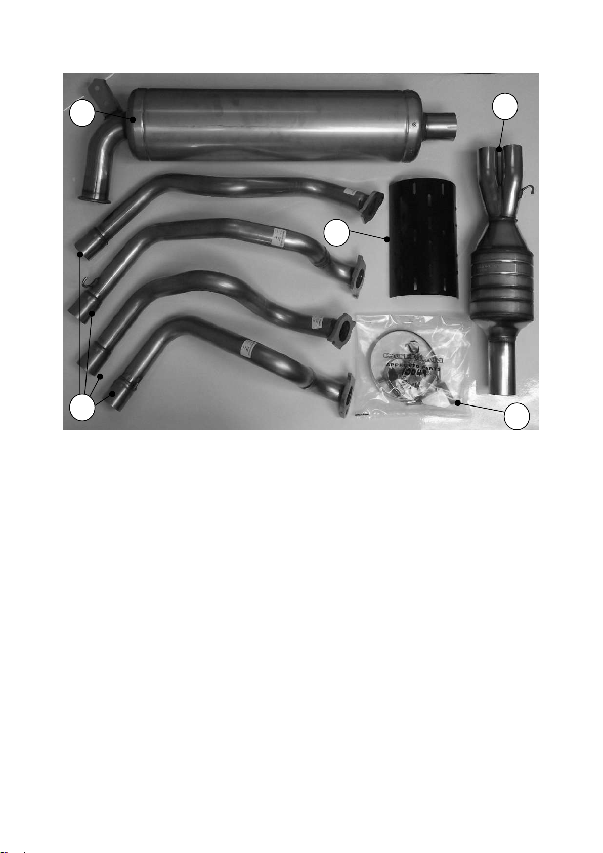
1. Exhaust silencer
2. Exhaust primary pipes
3. Cat/ collector
4. Cat guard
5. Polythene bag
Figure 1: Exhaust
NOTE
Items may differ from those illustrated
Page | 22
Page 24

Identifier
Description
Qty
Gearbox
Gearbox mounting rubber
Gear knob
Speedo drive cover
Reverse light switch
Speedo blanking plug
1
1
1
1
1
Steering
Track rod ends
Universal joint
Aluminium steering rack clamps
Steering column bush
Grub screw
Steering column clamp
Steering column plate
2
1
2 pairs
1
1
1
1
Exhaust
Jubilee clips
Exhaust clamp
Exhaust mounting bracket
Mounting bobbins
Exhaust springs
Lambda sensor
5
1
1
1
2
1
Wheels
Wheel nuts
Wheel nut washers
Centre caps
Centre cap badges
16 or 18
16 or 18
4 or 5
4 or 5
Table 2: Polythene bag contents - exhaust, steering, suspension items, bell-housing
and front wingstays
Page | 23
Page 25
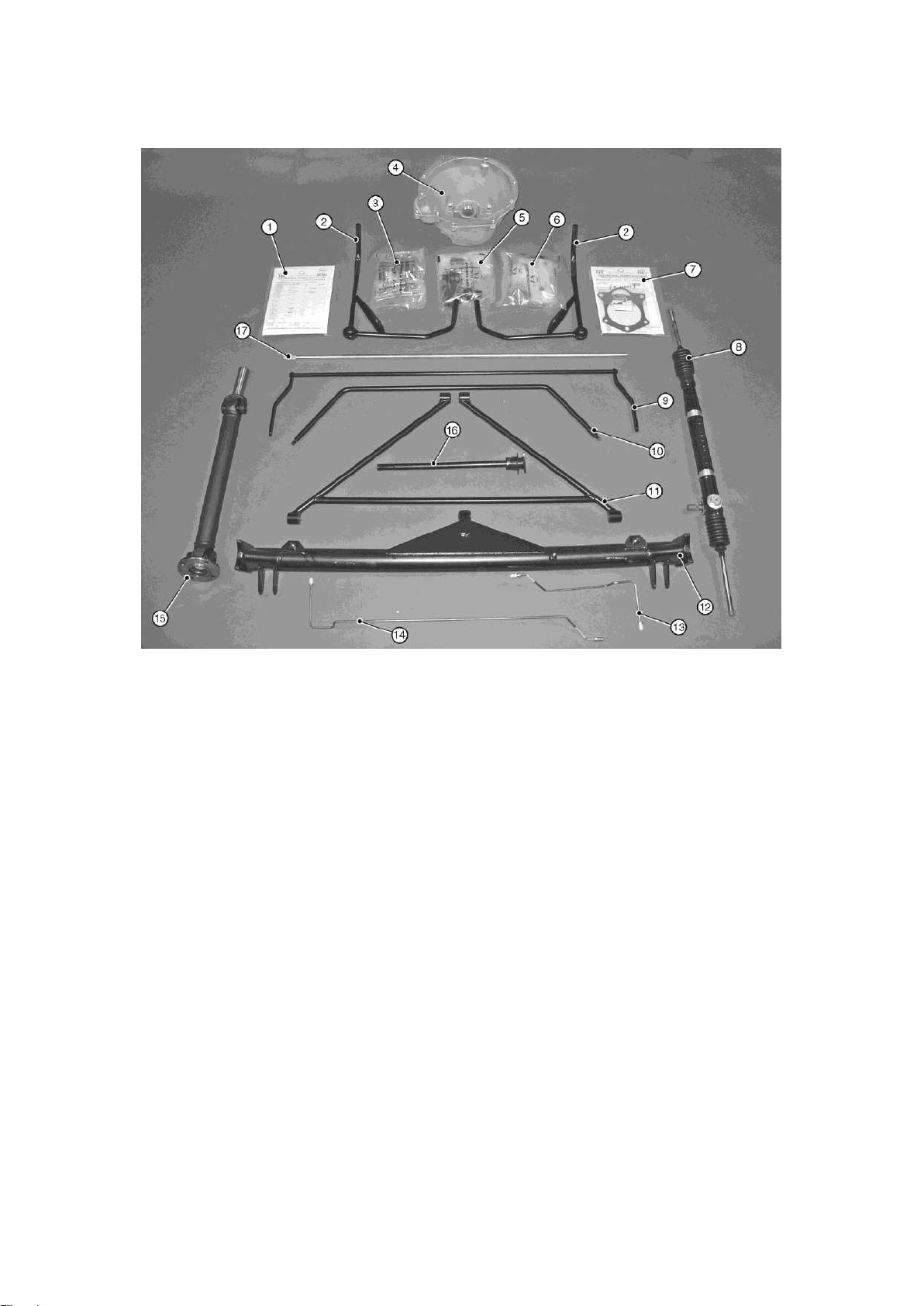
1. Fastener pack ‘steering’
10. Front anti-roll bar
2. Front wingstay
11. ‘A’ frame
3. Polythene bag ‘steering’
12. De Dion tube
4. Bell housing
13. Brake pipe (short)
5. Polythene bag ‘steering’
14. Brake pipe (long)
6. Polythene bag ‘wheels’
15. Propshaft
7. Fastener pack ‘gearbox’
16. Upper steering column and QR boss (optional)
8. Steering rack
17. Lower steering column
9. Rear anti-roll bar
Figure 2: Steering, large suspension items, bell-housing and front wingstays
Page | 24
Page 26
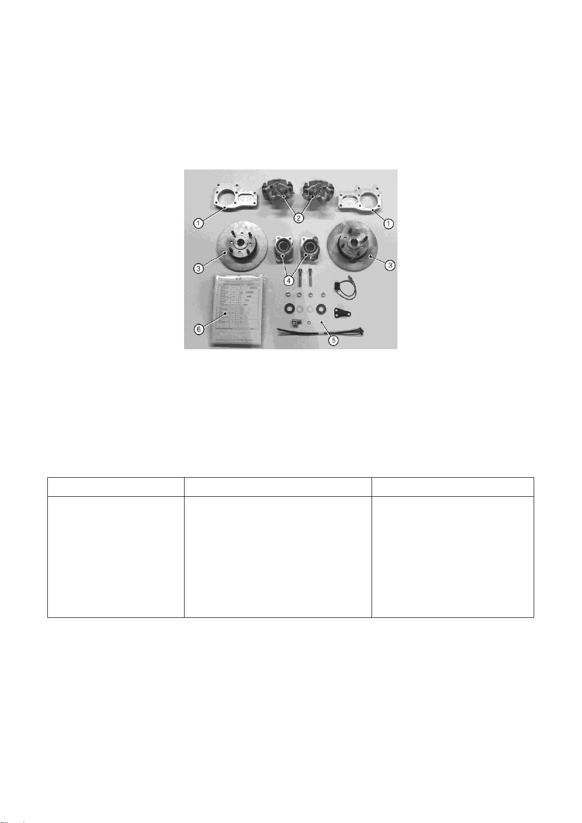
1. De Dion ears
4. Hub/bearing assembly (2)
2. Brake calliper (2, LH and RH)
5. Polythene bag ‘rear axle’
3. Brake disc
6. Fastener pack 30R011A
Identifier
Description
Qty
Rear Axle
Cable ties
Aluminium brake calliper spacers
Drive shaft washer
3-way brake union
Race washers
Rear brake pads
-
4
2
1
2
4
2.1.2) Rear axle
The rear axle items are shown in Figure 3. The contents of the polythene bag are detailed
in Table 2.
Figure 3: Rear axle items
Table 3: Polythene bag contents - rear axle
Page | 25
Page 27
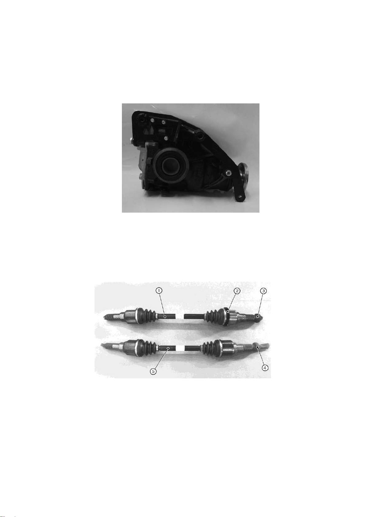
1. RH driveshaft
4. Nyloc nut (white insert)
2. Speed sensor ring
5. LH driveshaft assembly
3. Nyloc nut (green insert)
Figure 4: Differential
2.1.3) Differential
The differential is shown in Figure 4.
2.1.4) Driveshafts
The driveshafts are shown in Figure 5.
Figure 5: Driveshafts
Page | 26
Page 28
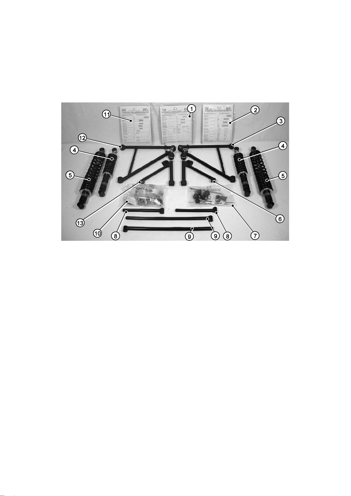
1 Fastener pack 30R012A
8 Watts link (rear) radius arm
2 Fastener pack 30R011A
9 Watts link (front) radius arm
3 Lower wishbone (RH)
10 Polythene bag ‘rear suspension’
4 Spring damper unit (front)
11 Fastener pack 30F015A
5 Spring damper unit (rear)
12 Lower wishbone (LH)
6 Upper wishbone (RH)
13 Upper wishbone (LH)
7 Polythene bag ‘front suspension’
2.1.5) Suspension
The suspension items are shown in Figure 6. The contents of the polythene bags are
detailed in Table 3.
Figure 6: Suspension items
Page | 27
Page 29

Identifier
Description
Qty
Front suspension
Rubber cotton reel bushes
Damper sleeves
Anti-roll bar rubber cover
Anti-roll bar ball ends
Cables ties
Anti-roll bars mounting clamps
Wishbone sleeves
Special stepped nyloc nut (widetrack/SV)
2
4
2
2
-
2
2
2
Rear suspension
(including rear anti-roll
bar option)
Rubber cotton reel bushes
Aluminium mounting blocks
Bellcrank (Watts link)
Bellcrank spacer
Rod end (Watts link)
ARB mounting boss
Anti-roll bar extension
Thrust washer
2
2 pairs
2
2
4
2
1
2
Table 4: Polythene bag contents - suspension
Page | 28
Page 30
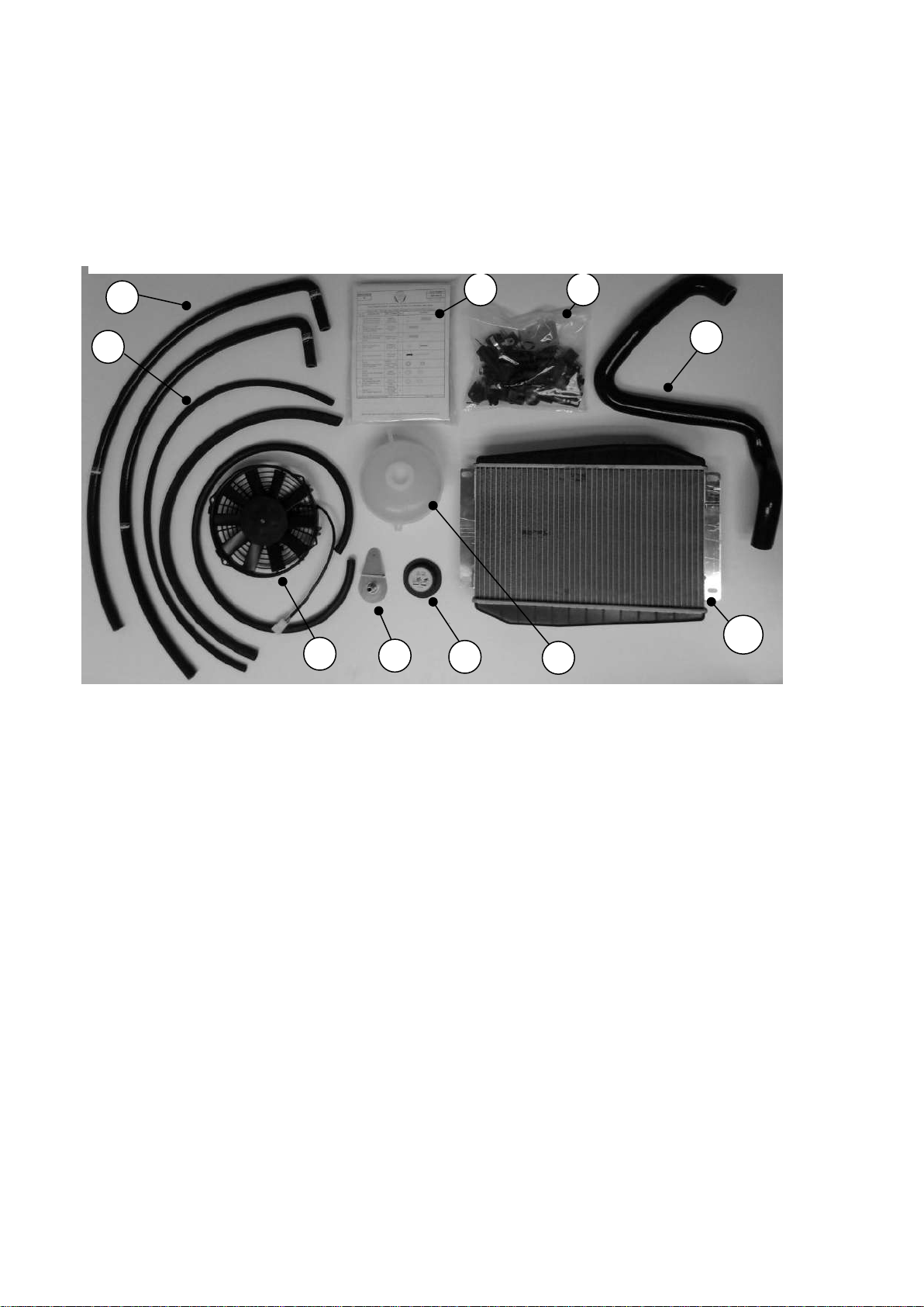
1. Expansion bottle hose
6. Cooling fan
2. Hose
7. Expansion bottle bracket
3. Fastener pack ‘cooling’
8. Expansion bottle cap
4. Polythene bag ‘cooling’
9. Expansion bottle
5. Bottom radiator hose
10. Radiator
1 3 4 5 2
Figure 7: Cooling items
8
7
6
9
2.1.6) Cooling
The cooling items are shown in Figure 7.
NOTES
(1) A thermostatic fan switch may be supplied in lieu of a blanking plug (if supplied, the
switch must not be connected to the vehicle wiring harness).
(2) If supplied, the water bleed pipe may be fitted to the engine.
(3) Items may differ from those illustrated, dependant on kit specification.
Page | 29
Page 31
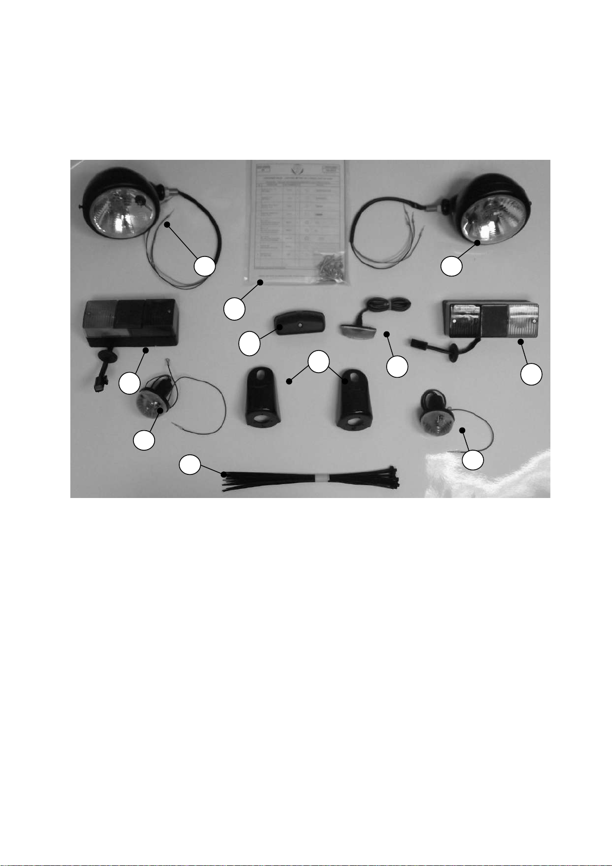
1. Headlight
5. Indicator repeater x2
2. Fastener pack 30L002A
6. Rear light cluster
3. Indicator cones (l/h and r/h)
7. Cable ties
4. Indicator (front)
8. Number plate light
Figure 8: Lighting items
3
7
4
6
6
8
2
5
4
1
1
2.1.7) Lighting
The lighting items are shown in Figure 8.
Page | 30
Page 32
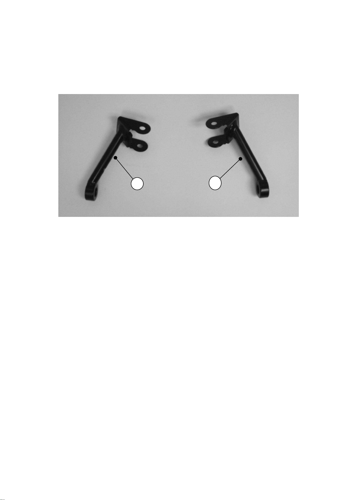
1. LH headlight bracket
2. RH headlight bracket
Figure 9: Headlight brackets
1
2
2.1.8) Head light brackets
The headlight brackets are shown in Figure 9.
Page | 31
Page 33
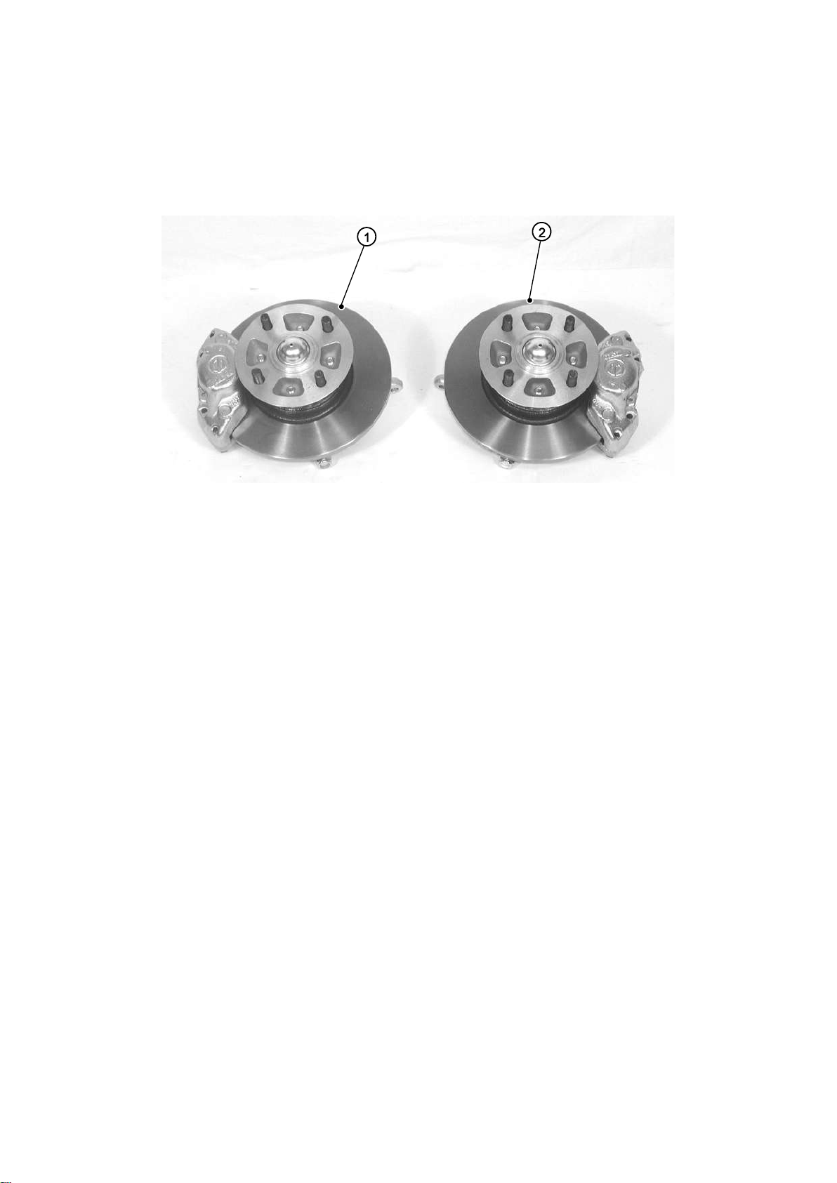
1. Upright assembly (RH)
2. Upright assembly (LH)
2.1.9) Uprights
The uprights are shown in Figure 10.
Figure 10: Uprights
NOTE
It is possible that the callipers may be supplied loose and not attached to the upright
assembly. If this is the case, the callipers need to be attached with the two bolts and shim
washers torqued to 58Nm.
Page | 32
Page 34
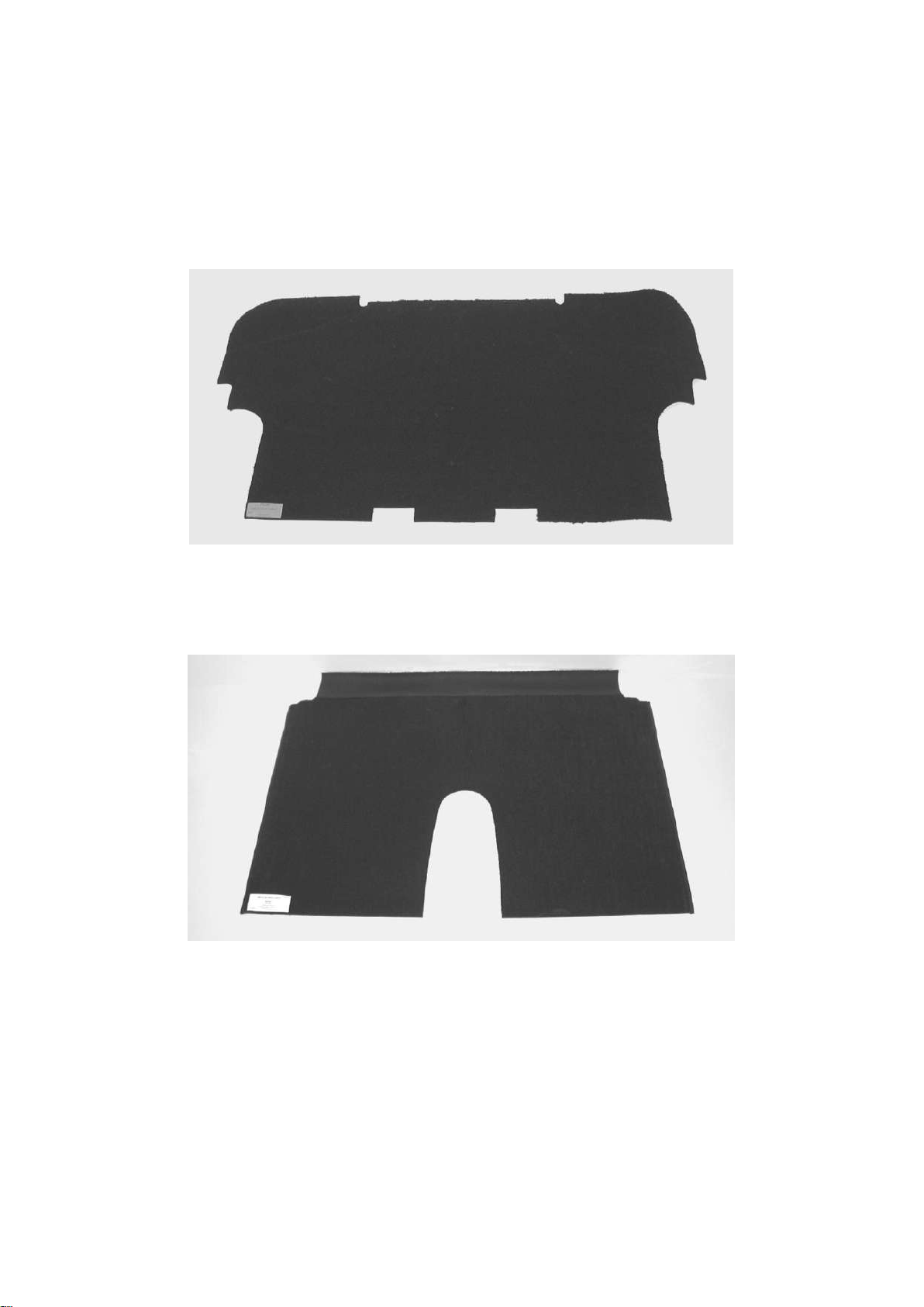
2.1.10) Interior trim, cables and options
The interior trim, cables and options items are shown in Figures 11, 12, 13 and 14. The
contents of the polythene bags are detailed in Table 4.
Figure 11: Boot carpet
Figure 12: Bulkhead carpet
Page | 33
Page 35
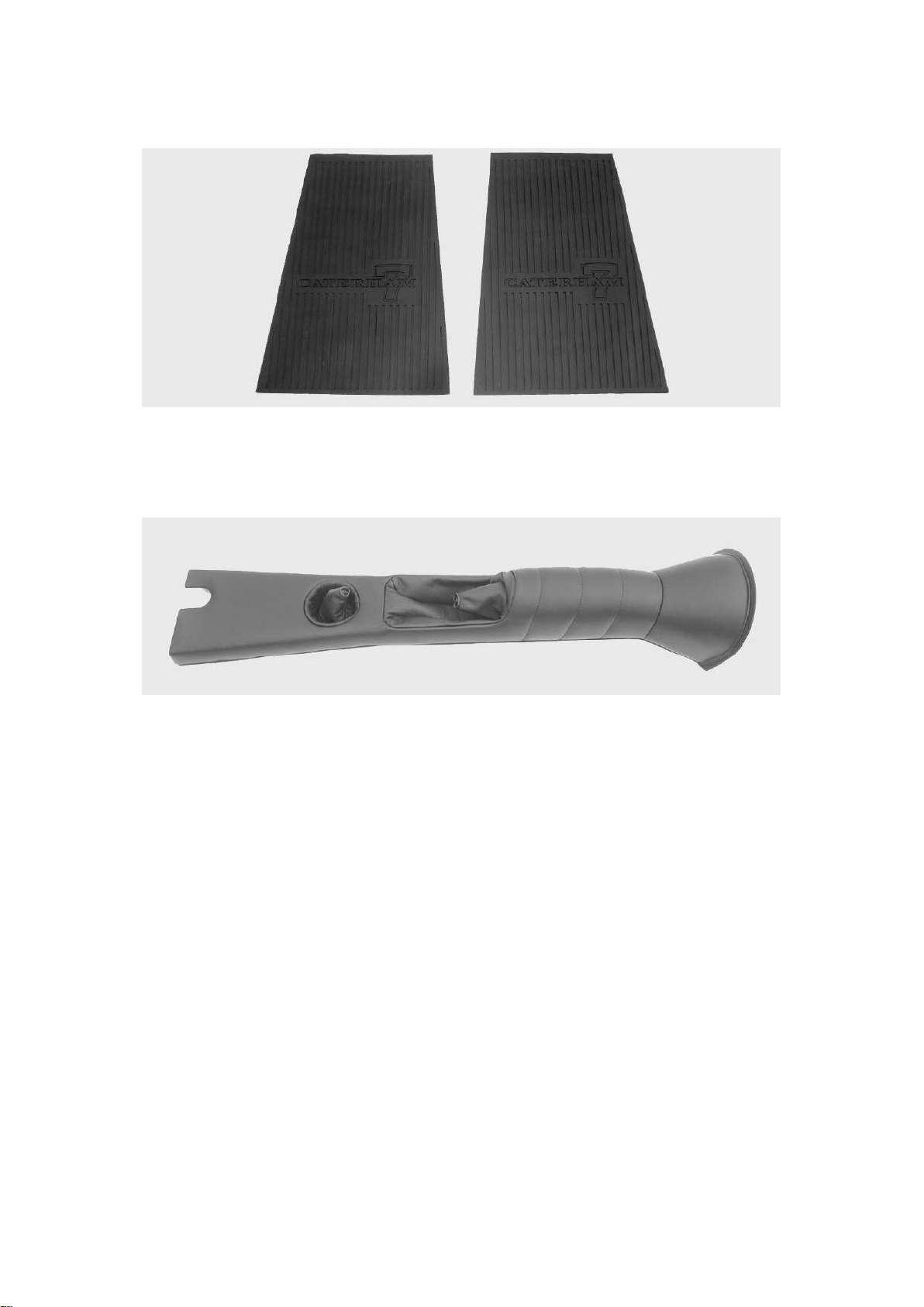
Figure 13: Rubber mats
Figure 14: Transmission tunnel top
Page | 34
Page 36

Identifier
Description
Qty
SVA
Cable ties
Track rod end sleeves
Track rod end bottom cap
Wing mirror pack
Sticky back foam (roll)
Edge trim (roll)
Large flat bolt head covers
Small domed caps
Long bonnet catch rubbers
Short bonnet catch rubbers
Large domed caps
Medium domed caps
-
2
2
1
1
1
6
12
2
2
2
4
Spare Wheel
Wheel nuts
Spare wheel bolt
Spacer
Mounting wishbone
2
1
1
1
Table 5: Polythene bag contents - interior trim, cables and options
Page | 35
Page 37
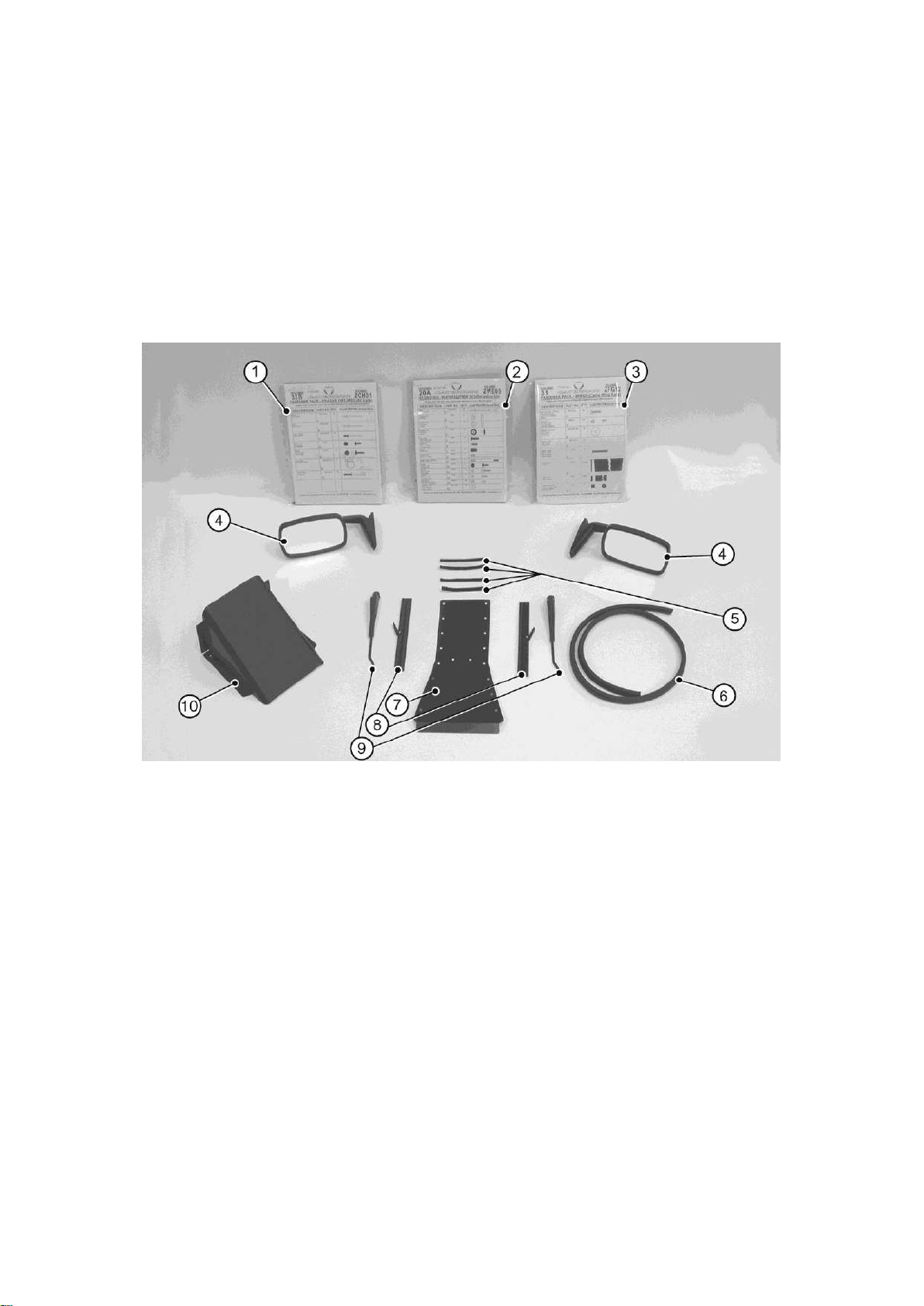
1. Fastener pack ZCH
6. IVA trim
2. Fastener pack ZWE
7. Transmission tunnel cover
3. Fastener pack 30P016A
8. Wiper blades
4. Side screen mirrors
9. Wiper arms
5. Velcro strips
10. Fuel filler cover
2.1.11) Deleted
2.1.12) Chassis/body unit
The chassis body unit comprises; chassis, body panels, pedals, master cylinder,
instruments, switches, wiring loom, windscreen, fuel tank, fuel pump, fuel lines, ECU.
Additional items placed loose in the chassis are shown in Figure 17.
Figure 15: Items loose in chassis
NOTE
If the optional weather gear has been specified, the side screen mirrors will be supplied in
the weather gear pack.
Page | 36
Page 38
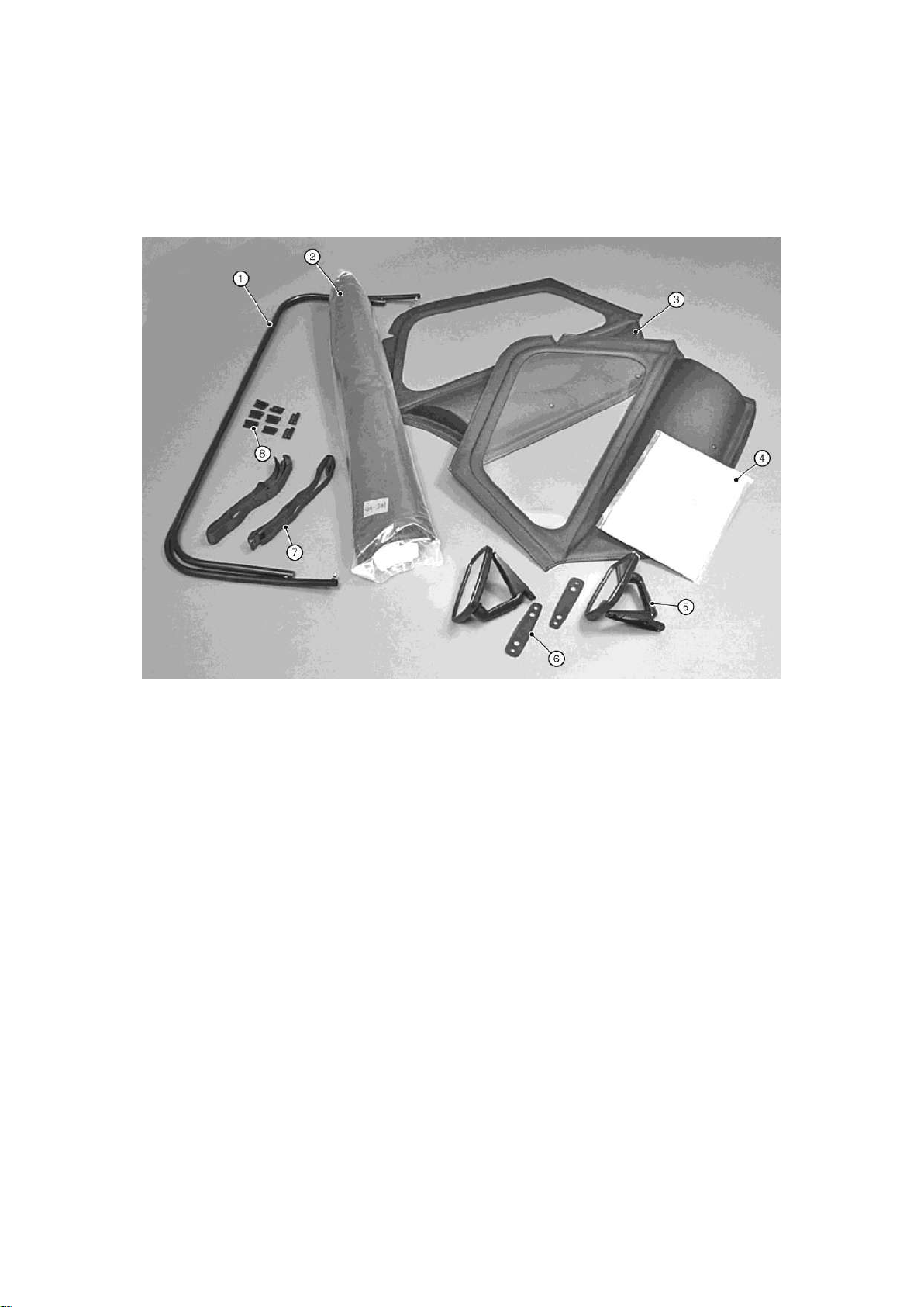
1. Hoodsticks
5. Mirrors
2. Hood
6. Mirror plate (not required)
3. Side screens
7. Hood straps
4. Fastener pack ‘weather’
8. Hinges
2.1.13) Weather gear (optional)
The optional weather gear items are shown in Figure 18.
Figure 16: Weather gear (optional)
Page | 37
Page 39
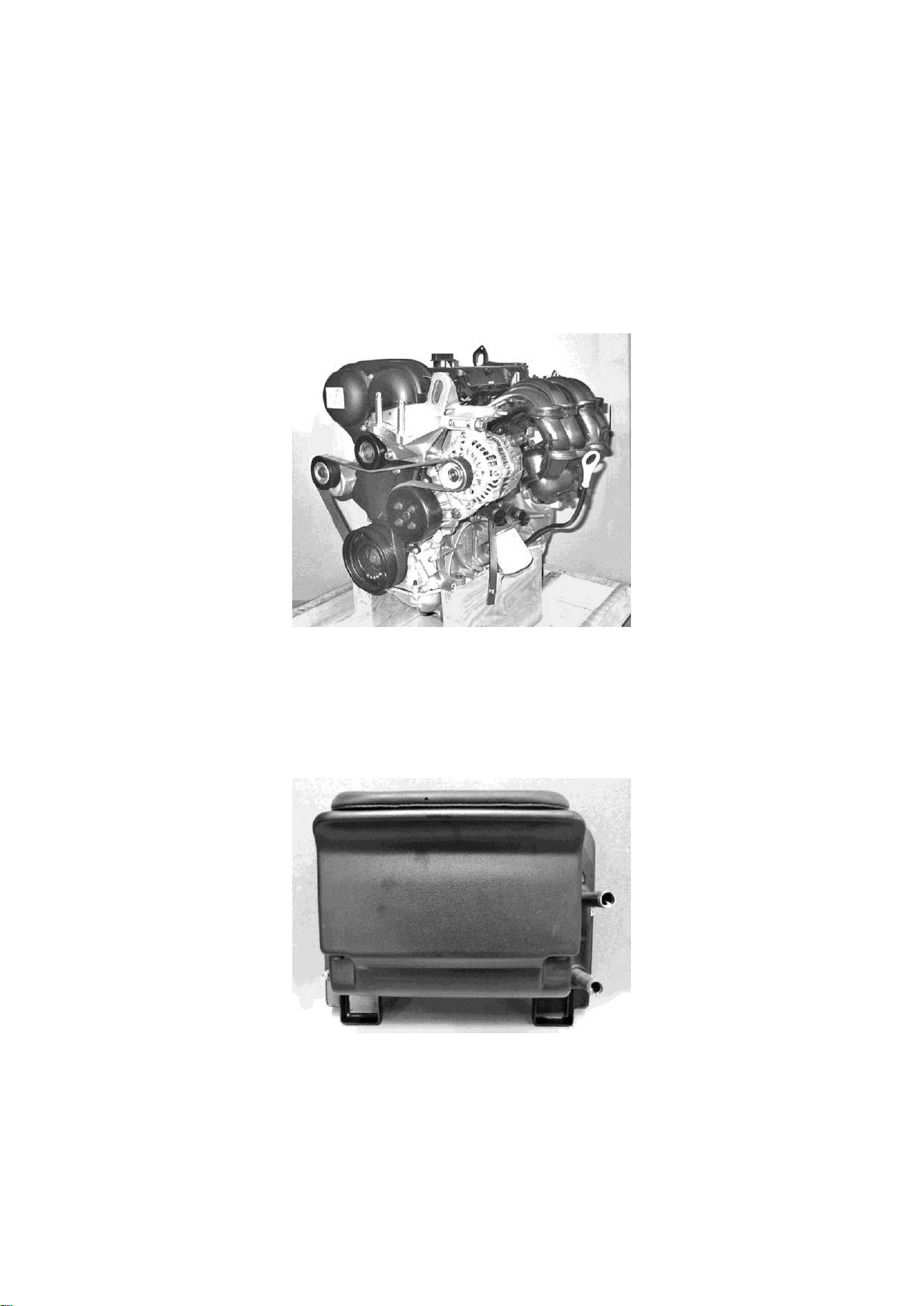
2.1.14) Engine
The engine, Fig 19, is supplied on a frame complete with engine mountings and lifting eyes.
Once the engine is fitted the lifting eyes must be removed. The engine is supplied
complete with wiring loom. The starter motor is not fitted as it is secured to the bellhousing.
Figure 17: 1.6 sigma engine
2.1.15) Heater assembly
The heater assembly, Figure 20, is packed into an unmarked cardboard box.
Figure 18: Heater assembly
Page | 38
Page 40

2.1.16) Wheels
The alloy wheels are supplied with tyres already fitted. It should be noted that the tyres
may be handed, that is, have a direction of rotation arrow showing the direction of travel.
Wheels must be fitted with the directional arrow in the correct direction.
2.1.17) Seat
The seats are supplied in protective covers. It is recommended that the covers are not
removed until the seats are required for fitment.
2.1.18) Wings
The front and rear wings are supplied protected with bubble wrap. The two largest wings
are for fitment to the rear of the car.
2.1.19) Nosecone
The nosecone is supplied in protective bubble wrap. It is recommended that it is left
protected until required for fitment.
2.1.20) Roll over bar
The roll over bar is protected by bubble wrap and is supplied in its own box.
Page | 39
Page 41

Box
Package
Contents
Box 1
Steering, exhaust,
gearbox assembly,
drive shafts
Steering rack, rack clamps, upper and lower steering columns,
column bush, column clamp, track rod ends. Grub screws,
silencer assembly (standard system). Primary pipes (4), collector
or catalyst collector, silencer (competition system), catalyst heat
guard, mounting brackets and bobbins, wheel nuts, centre caps,
badges, bell-housing, clutch release mechanism, speed sensor
and threaded adapter, reverse light switch, mounting rubber,
gearknob, front and rear anti-roll bars and fixings, cycle
wingstays, 'A' frame, differential driveshafts and nuts, De Dion
Tube, brake pipes, propshaft
Box 2
Axle (De Dion)
Disc pads and callipers, drive flanges, De Dion ears, hub,
bearings
Box 3
Differential
Differential assembly
Box 4
Front suspension,
rear suspension
Spring damper units, upper and lower wishbones, spring damper
units, radius arms/Watts linkage
Box 5
Cooling
Coolant hoses, water rail, cooling fan, heater (option on
Superlight), bobbins, expansion bottle and cap, radiator cowling
Box 6
Lighting
Headlamp units, headlamp brackets, indicator pods, indicators,
number plate light, reversing light, fog light, side repeaters, horns
Box 8
Interior trim
Covered tunnel top, tunnel side carpets, footwell mats, seat back
carpets, hood, hood sticks, boot cover, pulley and cables, throttle
3.0) Pre-assembly information
This section has been included to aid recognition of parts and to give a basic idea as to
where they might be found. Due to the complexity of the range of options available and
subsequent variations on packages it is impossible to list every permutation; however Table
5 (below) and Annex A (at the end of this section) show the normal location of parts in a
standard CKD kit.
3.1) Package contents
Kits supplied from Caterham Cars arrive as shown in Fig 21. Due to packaging constraints
some items may be located in different packages.
Table 6: Package contents
Page | 40
Page 42

cable, clutch cable, rear wing protectors, steering wheel, spare
wheel wishbone, seat belts and fixings, tonneau cover, seat
runners, seat spacers, assembly guide, arm restraint, hardware
packs, IVA packs.
Box 9
Weather
equipment
Hood straps, exterior mirrors, fuel filler cover, hinges
(sidescreen), sill protectors, wiper arms, wiper blades, hardware
pack, mirrors
Box 10
Airbox/air intake
system
Airbox and fixings
Own box
Uprights
Front uprights assemblies inc brakes on uprated uprights
Pallet
Engine
Complete engine and clutch, engine loom, engine mounting
brackets
Loose
Sidescreens
Own box
Gear box
Own box
Radiator
Loose
Exhaust silencer
Loose
Wheels and tyres
Alloy wheels and tyre assemblies
Loose
Seats
Own box
Roll over bar
On
Chassis
Chassis/body unit
Chassis, battery, body panels, pedals, master cylinder,
instruments, switches, wiring loom, fuel tank, fuel pump, fuel
lines, ignition module/ECU. Rear wings, front wings, nosecone,
battery, battery clamp/tray, knee trim panels, scuttle trim,
econoseal plugs, steering column plate, grilles (Mesh 7), int panel
trim, keys (ignition, fuel cap, battery master switch), aluminium
tonneau cover, paint touch bottles
Page | 41
Page 43
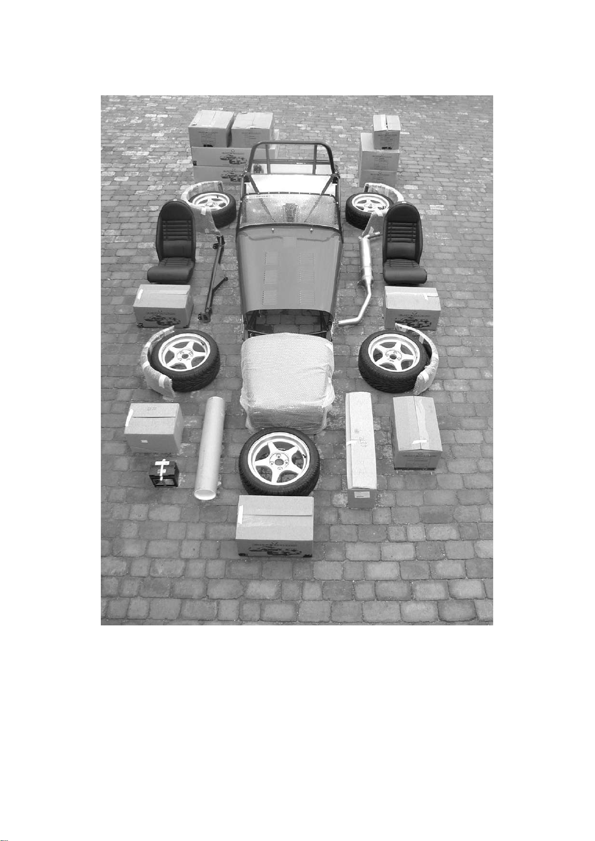
Figure 19: Complete kit (less engine)
Page | 42
Page 44

3.2) Basic definitions
Item
Remarks
Socket set
Metric and imperial
Spanner set
Metric and imperial
Screwdriver
Flat point (various)
Screwdriver
Phillips/posidrive
(various)
Soft faced hammer
Rubber/plastic/
copper/hide
Circlip pliers
Torque wrench
0-80 Nm
Allen Keys
Metric
Measuring tape
Hacksaw
Rivet gun
Goggles
Eye protection
Twist drill bits
Metric and imperial
Crimp pliers
Drill
Preferably
rechargeable
Axle stand
Qty 4
Jug/small funnel
Item
Remarks
Engine hoist
SWL of 150 kg
Socket 41mm
Torque wrench
Up to 275 Nm
Cut down allen key
3/8” for 6 speed
10 mm for 5 speed
Gearbox oil filler plug
Durable Dot fastening
tool
76068 – supplied with
chassis kit
The text in the assembly guide refers to
the Right Hand (RH) side or Left Hand
(LH) side of the car. For all purposes the
RH side of the car is taken to be the
driver’s side of a RH drive car.
Also mentioned in the assembly guide are
the terms inboard (pointing towards the
centre line of the car) and outboard
(pointing away from the centre line of the
car).
3.3) Tools and equipment
All kits supplied by Caterham Cars are
specifically designed for the amateur car
builder with basic facilities. Table 7
details the general purpose tools that will
be required during the build process.
Table 7: Tools required
The tools detailed in Table 8 are not
generally to hand in the amateur
workshop. These will be required during
the build process.
Table 8: Additional tools and
equipment
Page | 43
Page 45
Item
Type
Remarks
Rubber
lubricant
Holts RL2R
To ease
assembly and
operation of
rubber bushes
and grommets
Copper
grease
Comma
Copper
ease
Anti-seize
compound where
lubrication is not
required to
ensure ease of
future
disassembly
Threadlock
Loctite
threadlock
242 or 243
Used where the
application
prevents the use
of nyloc nuts or
spring washers
Silicone
sealant
Clear
To achieve a
watertight seal.
It should be
applied sparingly
Masking
tape
Duct tape
Protection of
body
Adhesive
Contact
Carpet/trim
Item
Ford Sigma
Duratec
Rover
Engine oil
Ford engine oil
formula E-5W30
Caterham
motorsport
oil 5W-50
Caterham
motorsport oil
5W-50
Caterham
motorsport
oil 5W-50
Comma XTEC 5W-30
semi synthetic
Comma XTEC 5W-30
semi
synthetic
Gearbox oil
(5 and 6
speed)
Caterham
gearbox oil EP
80 grade
Caterham
gearbox oil
EP 80grade
Caterham
gearbox oil
EP 80
grade
Item
Ford Sigma
Duratec
Rover
Differential
(All)
Caterham
differential oil
EP90
Caterham
differential
oil EP90
LSD –
additive
Lubeguard
limited slip diff
Lubeguard
limited slip
The engine hoist should only be required
for a short time and can usually be
sourced from a tool hire company. The 41
mm socket and torque wrench will be
required to tighten the rear hubs to the
drive shafts and the cut down Allen key is
required to tighten the gearbox oil filler
plug, due to the restricted access in the
transmission tunnel. The key can be
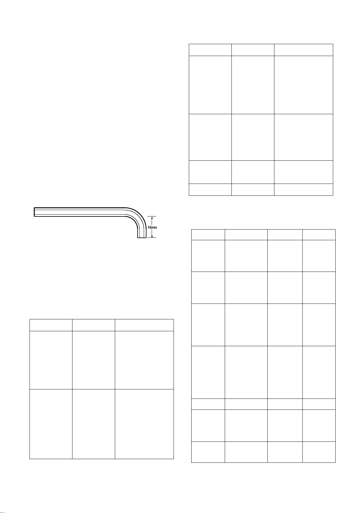
modified as shown in Fig 22.
Figure 20: Cut Allen key
The consumables detailed in Table 9 and
recommended lubricants detailed in Table
10 are required during the build process.
Table 9: Consumables
Table 10: Recommended lubricants
Page | 44
Page 46

additive
diff additive
Brake fluid
Comma DOT4
Comma
DOT4
Engine
coolant
Comma
Xstream red or
ford super plus
anti-freeze
Comma
Xstream red
or ford
super plus
anti-freeze
Comma
Xstream
red
Thread
Socket size
Torque
(Nm)
1/4” UNF/UNC
7/16” A/F
7
5/16” UNF/UNC
1/2” A/F
20
3/8” UNF/UNC
9/16” A/F
34
7/16” UNF
5/8” or 11/16”
A/F
47
1/2” UNF
3/4” A/F
61
5mm
10mm
6
6mm
11mm
7
8mm
13mm
20
10mm
17mm
47
12mm
19mm
61
kits. Any unmarked bolt should not be
used.
Ensure that the correct tightening torque
is applied. Where torque figures are not
specified, use the figures detailed in Table
11. Particular care must be taken when
It is recommended that a sturdy
workbench and a good vice are made
available for holding items stable.
The application of undue force should not
be necessary if assembly is carried out in
the correct sequence.
3.4) Nuts, bolts and washers
As a general rule the fasteners used are
RH thread and of Metric dimensions.
Some Imperial fasteners are still used,
particularly within the brakes and
suspension.
using the torque wrench to tighten
fastenings into aluminium.
Table 11: General torque figures
Always assume that bolts and fasteners
are not properly tightened until they have
been specifically checked.
All safety critical fastenings supplied by
Caterham Cars are high tensile
conforming to British Standards 1768
(Imperial) and 3692 (Metric). Customers
supplying their own fasteners should only
use fasteners with heads marked 10.9
and 12.9 particularly when attaching
suspension, steering, upright and axle
It is good practice to mark the bolt head or
nut with a spot of paint once it has been
finally tightened. This provides a good
visual means of checking that all fixings
have been set to the correct torque.
Over tightening can often cause more
problems than under tightening, such as
sheared bolts and studs and incorrect
stresses.
Page | 45
Page 47

The majority of fastenings have washers
inserted between the nut and or bolt head
and the item being secured. Spring
washers or lock washers are usually
placed next to the bolt head or nut then
the plain washer. As a general rule the
following washers are used as detailed:
Plain washer
To protect the surface and spread
a load when attaching to a soft
material such as glass fibre or
aluminium.
To adjust the spacing of one
component to another use plain
washers of appropriate thickness
and external diameter.
To prevent migration (sideways
movement) of rubber bushes.
The large plain chamfered washers
are often used in conjunction with
the metalistic suspension bushes.
Where this is the case the
chamfered edge must be fitted
towards the bush to prevent
contact with the outer metal part of
the bush.
Particular care should be taken to ensure
that the correct fastening is being used,
since it is possible to use an overlong bolt
only to find that it is apparently missing
when the only remaining bolts are too
short.
To present a uniform surface on
which to tighten a fastening onto a
rough or irregular surface.
Spring washer
To lock a thread where there is a
possibility of the nut or bolt working
loose. Not used with a nyloc nut.
Large diameter, thin plain washer
To spread a load onto very thin
material.
Large diameter plain washer
The majority of fasteners supplied by
Caterham are in polythene bags with an
A4 sheet on a card insert, refer to Fig 23.
The A4 sheet can be used to confirm that
the contents are correct. Each pack has a
unique number, located at the top RH
corner and each item within the pack can
be identified by a number at the bottom
LH corner of the part number box. Where
fasteners are specified in the text, the
unique pack number will be stated the first
time it is required along with the
description and the Item Identification
number in brackets. The next time an
item from that pack is required it will be
identified by description and the Item
Identification number only, for example:
Page | 46
Page 48

Bolt (fastener pack 30P017A
Item 1) identifies the Bolt M8 x 50
mm from the fastener pack
illustrated at Fig 23.
At a later point in the same section
of text ‘nut (4)’ identifies the M8 nut
from the same fastener pack.
NOTE
Imperial and metric fasteners are supplied
together in some packs. Ensure that the
correct threadform is identified before use.
Page | 47
Page 49
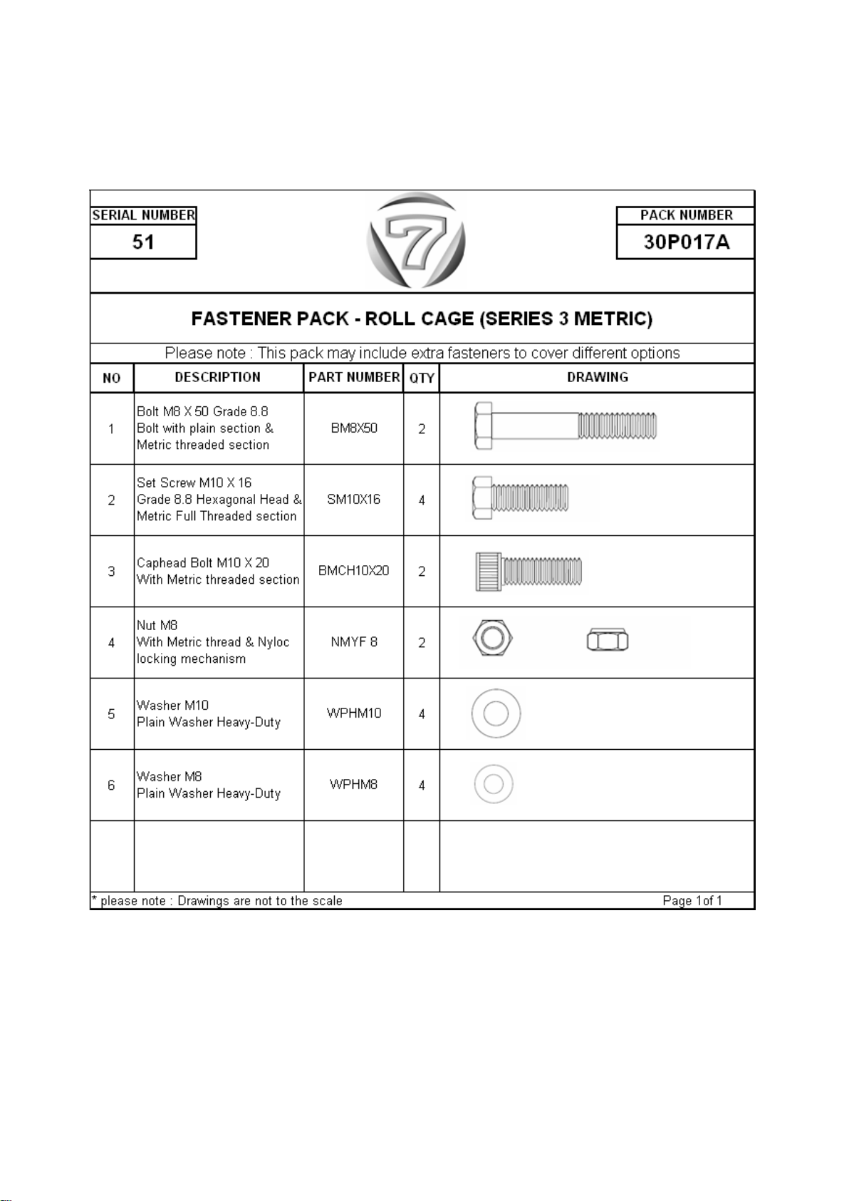
Figure 21: Fastener pack
Page | 48
Page 50
3.5) General build information
Caterham Seven builders should take
care to observe basic safety precautions
whilst assembling the kit since tools, parts
and materials handled incorrectly may
result in injury.
Due to circumstances beyond the control
of Caterham Cars, occasionally it is
necessary to change suppliers and/or to
make minor changes to the car or kit
specification.
If it is intended to build the car over a
short period (up to 4 weeks) it is
recommended that an application for the
IVA inspection is submitted as soon as
possible. There is usually a wait of 2-3
working on the car at different build
levels.
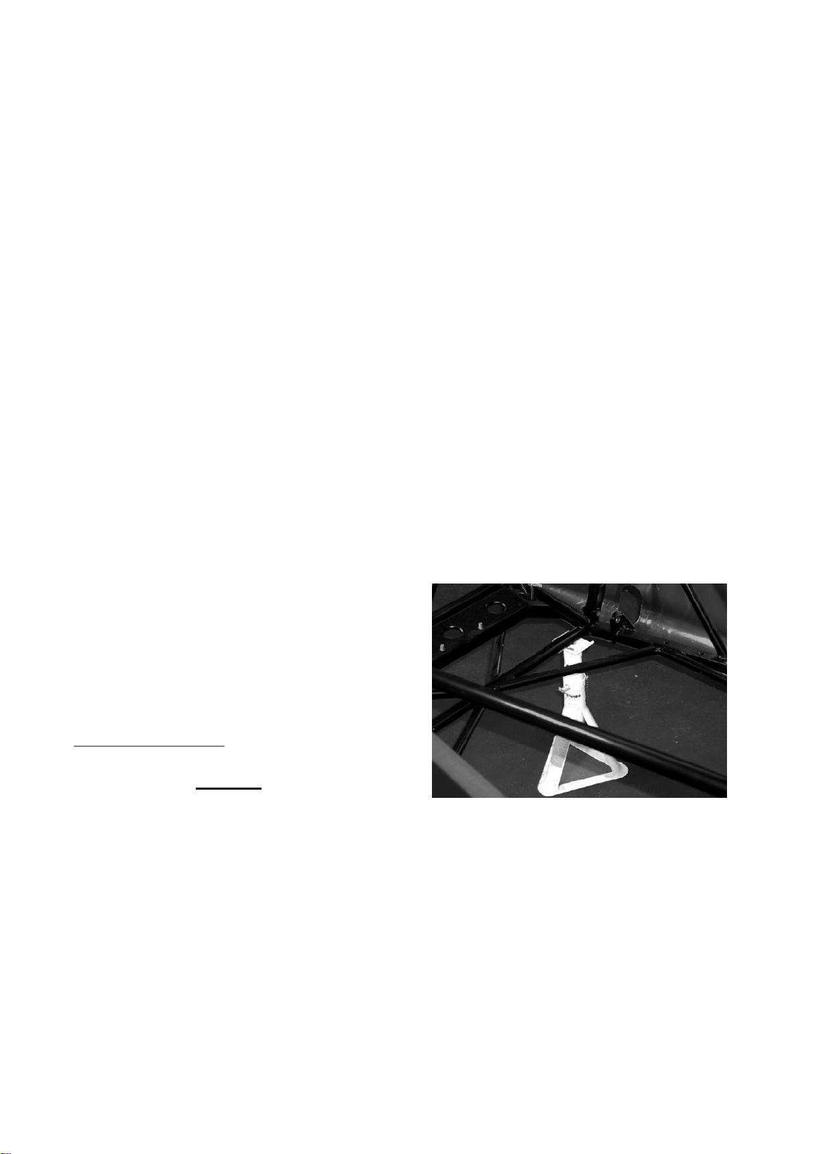
It is recommended that the chassis is
supported on 4 axle stands which will give
stability for both safe working and ready
access. Placing of the axle stands is
made easier if assistance is available. Lift
the front of the car and place the axle
stands at the outer ends of the second
chassis cross tube adjacent to the rear
mounting of the lower front wishbone
mounting, refer to Fig 24. If the car is
raised using a jack, ensure that it is
positioned under the front cruciform and
that the powder coat finish is protected.
Figure 22: Front axle stands
weeks, minimum. In addition it will take up
to a week for the Vehicle Inspectorate to
process the application. Full details about
applying for the IVA inspection can be
found in the IVA section or at
www.directgov.co.uk.
Warning
Never work underneath a car without
supporting it on axle stands or
equivalent. Do not rely on a jack alone.
For IVA inspection you will need
photographic evidence of the car build.
Caterham recommends that you
should take some photos of yourself
Page | 49
Page 51
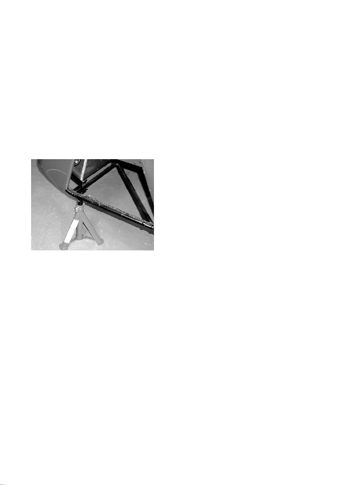
The rear axle stands should be positioned
at either end of the chassis tube that
supports the front of the fuel tank, refer to
Fig 25. If the car is raised using a jack,
ensure that it is positioned centrally and
the powder coat finish on the chassis tube
is protected.
Figure 23: rear axle stands
Page | 50
Page 52
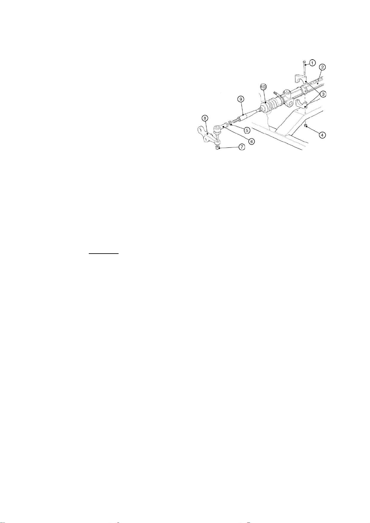
1. Securing bolt
6. Track rod end
2. Steering rack
7. Securing nut
3. Rack clamps
8. Steering arm
4. Nyloc nut
9. IVA cover
5. Locknut
10. Steering rack gaiter
4.0) Steering
The following section contains information
on steering rack (standard and wide
track), steering wheel fitments and other
associated tasks.
4.1) Steering rack (standard and wide
rack)
The steering rack should be fitted before
the front suspension. Before fitting the
steering rack it is advisable to protect the
outside of the aluminium side panels
around the circular cut-outs through which
the rack protrudes. Masking tape is
sufficient for this purpose.
Warning
Figure 24: Steering rack assembly
Clamp the rack loosely into place using
bolt (fastener pack 30S003A Item 1),
nyloc nuts (8) and rack clamps (3).
Never work underneath a car without
supporting it on axle stands or
equivalent. Do not rely on a jack alone.
Carefully pass the steering rack through
the circular cut-outs in the side panels
until the machined areas of the rack line
up with the holes in the rack platform.
Ensure that the rack pinion exits the rack
on the driver's side of the vehicle.
The steering rack is held in place by two
piece aluminium rack clamps (polythene
bag marked 'steering'). The rack clamps
are matched pairs and clamp the steering
rack into position as they are bolted into
Ensure a washer is placed between the
rack clamp and the nyloc nut. The rack
will be tightened later when the steering
column is correctly positioned.
Fit the IVA cover (polythene bag marked
'IVA' to the end of the steering rack arm,
ensure that the larger diameter is
outboard. Screw the locknut (Figure 26
item 5) onto the steering rack arm then fit
the track rod end. This should be
screwed on 11 full turns (S3) or 13 (SV) to
give an approximate track setting. Do not
tighten the locknuts.
place, refer to Figure 26.
Page | 51
Page 53
NOTES
(1) The IVA covers will need to be
trimmed on one end to fit over the tie rod
ends
(2) The IVA covers are secured using
cable ties. However this should not be
done at this stage as final adjustment to
the tracking will be required.
(3) Tracking is adjusted during final
checks.
4.2) Steering column
The steering column should not be fitted
until after the engine and gearbox have
been installed.
The front of the pedal box is sealed using
a grommet inserted into the hole through
which the steering column passes, refer to
Fig 27. The inside of the rubber grommet
should be smeared with rubber lubricant
to prevent wear.
Position the ‘cheese wedge’ (refer to
Figure 27) on the pedal box, aligned with
the hole for the steering column (it may be
necessary to trim the top edge of the
cheese wedge to avoid fouling the clutch
master cylinder). Mark the three hole
positions using the holes in the cheese
wedge as a guide. Drill the holes using
1/8” drill bit (it may be necessary to
remove the clutch master cylinder for
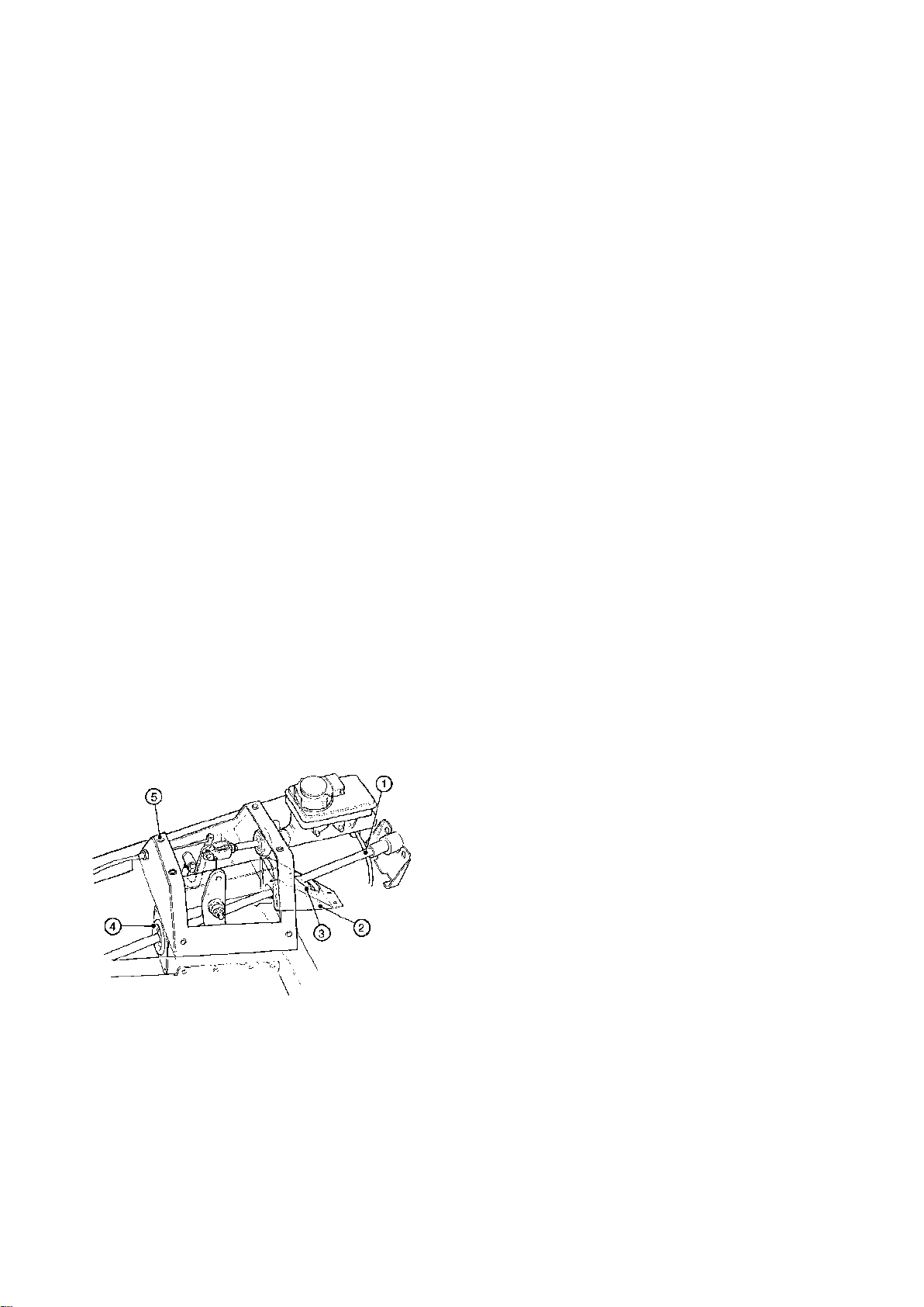
Remove the lid of the pedal box, refer to
Figure 27.
Figure 25: Pedal box
1 Lower steering column 3Grommet
2 Cheese wedge 4 Grommet
sealing box 5 Pedal box
(Clutch master cylinder and brake pipes
omitted for clarity)
access). Apply silicone sealant to the
seating edges of the cheese wedge and
secure the cheese wedge with rivets. Seal
the edges with sealant. Fit the grommet to
the large hole at the rear of the cheese
wedge. Coat the grommet with rubber
lubricant.
It is possible that the cheese wedge has
already been fitted to the chassis.
The lower steering column is inserted,
splined end first, through the dashboard
under the brake master cylinder, through
the rubber grommet in the 'cheese
wedge', through the pedal box and finally
through the rubber grommet in the pedal
box sealing plate.
Page | 52
Page 54
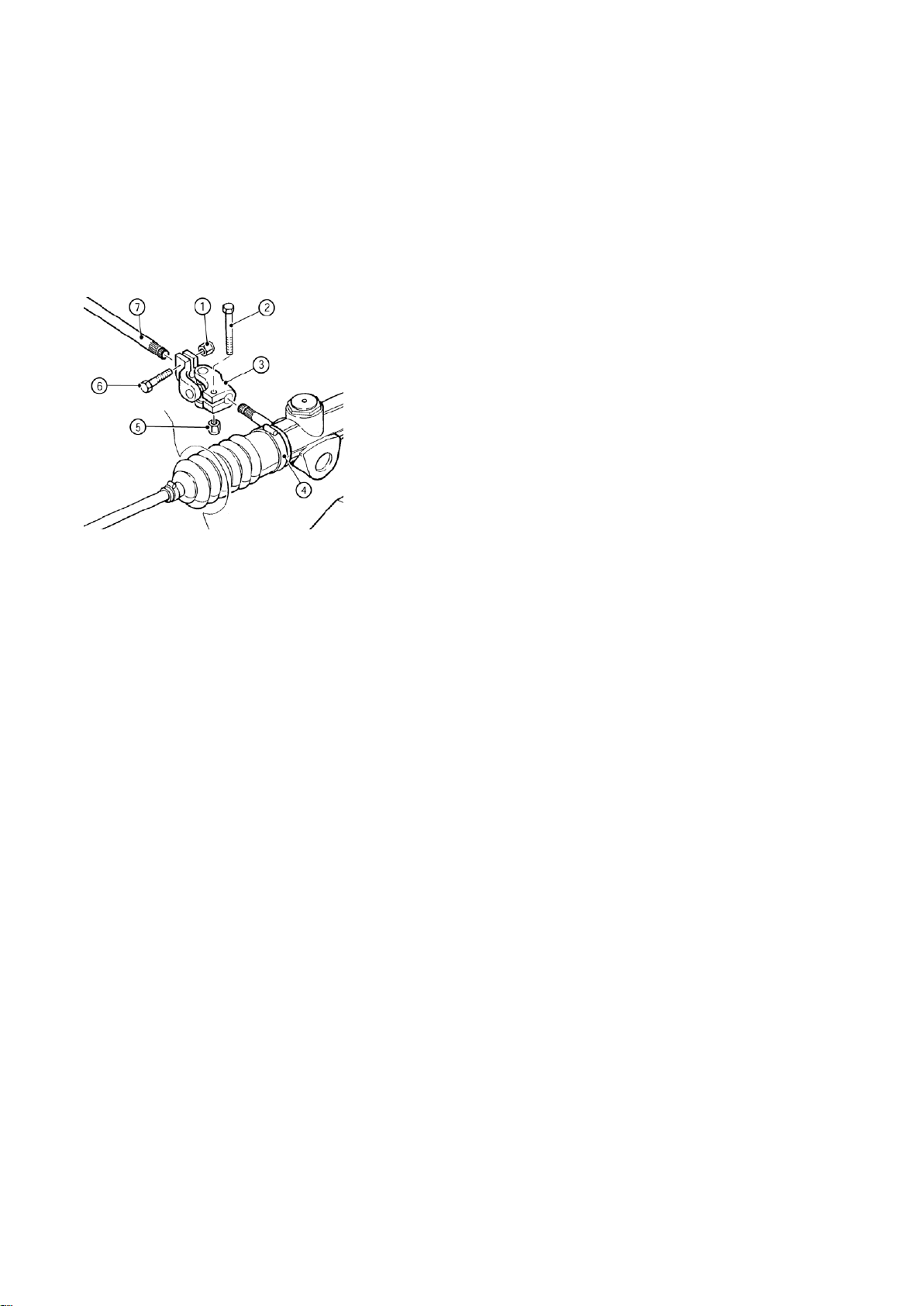
1. Nyloc nut
5. Nyloc nut
2. Bolt
6. Bolt
3. Universal joint
7. Lower steering
column
4. Steering rack
NOTE
Engine installation will be easier before
the lower steering column is fitted.
Figure 26: Steering rack to steering
column
vertical/horizontal when the steering
wheel is in the straight ahead position.
Fit the lower end of the universal joint onto
the rack, again clamping with the bolt and
nyloc nut and tighten both bolts to 11 Nm.
The universal joint should be run as
straight as possible, continuing along the
same angle as the column, the steering
rack can be turned in its blocks to achieve
this.
The upper steering column can now be
fitted.
NOTE
Position the front wheels (or uprights) in
an approximate ‘straight ahead’ position
and attach the universal joint (polythene
bag marked 'steering') using bolt (3) and
nyloc nut (7) noting how the bolt locates
into the machined groove in the splined
end of the lower steering column.
NOTE
If insertion is difficult the universal joint
can be opened up by inserting a flat blade
When fitting an optional, quick release
column the upper steering column bush
can be fitted prior to inserting the upper
steering column into the steering column
lock tube.
The lower column bush will have been
fitted by Caterham, but care must be
taken when sliding the upper steering
column down through the dashboard.
Ensure that the lowest portion of upper
steering column is liberally coated with
grease and minimum force is exerted.
Telescope the upper steering column over
the lower steering column.
screwdriver into the split and twisting. To
ensure linearity of response it is
recommended that the yoke of the
universal joint is positioned with the cross
Slide the upper steering bush onto the
column and into the dash tube. Note how
the raised rubber locators on the bush fit
in the holes in the dash tube.
Page | 53
Page 55
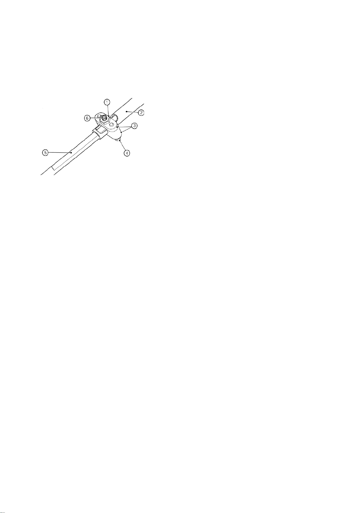
1. Locknut
4. Securing bolts
2. Upper steering
column
5. Lower steering
column
3. Clamp
6. Grub screw
To ease fitment lightly coat the upper
steering bush with rubber lubricant.
Figure 27: Upper steering column
clamp
NOTE
Before tightening the clamp:
Fit the steering wheel boss onto its spline
to ensure that the steering wheel boss
does not foul the dashboard. Slide the
steering column/steering wheel boss away
from the dashboard to achieve clearance.
Check that the lower steering column
does not foul the drive belt tension
mechanism on the engine. If necessary
rotate the steering rack in its clamps to
provide clearance.
Tighten the steering rack clamps
The two parts of the steering column are
clamped together using the locking clamp,
make sure the cut out faces the column,
refer to Fig 29. Insert the grub screw
loosely into the clamp. Secure the two
halves of the clamp using two bolts (2),
plain washers (10) and spring washers
(11). Torque to 14 Nm. Tighten the grub
screw with an Allen key to eliminate any
free play in the steering. Lock the grub
screw into place using locknut (6).
to 11 Nm. Ensure that the two bolts
securing the steering column lock tube to
the scuttle face are tight.
Page | 54
Page 56
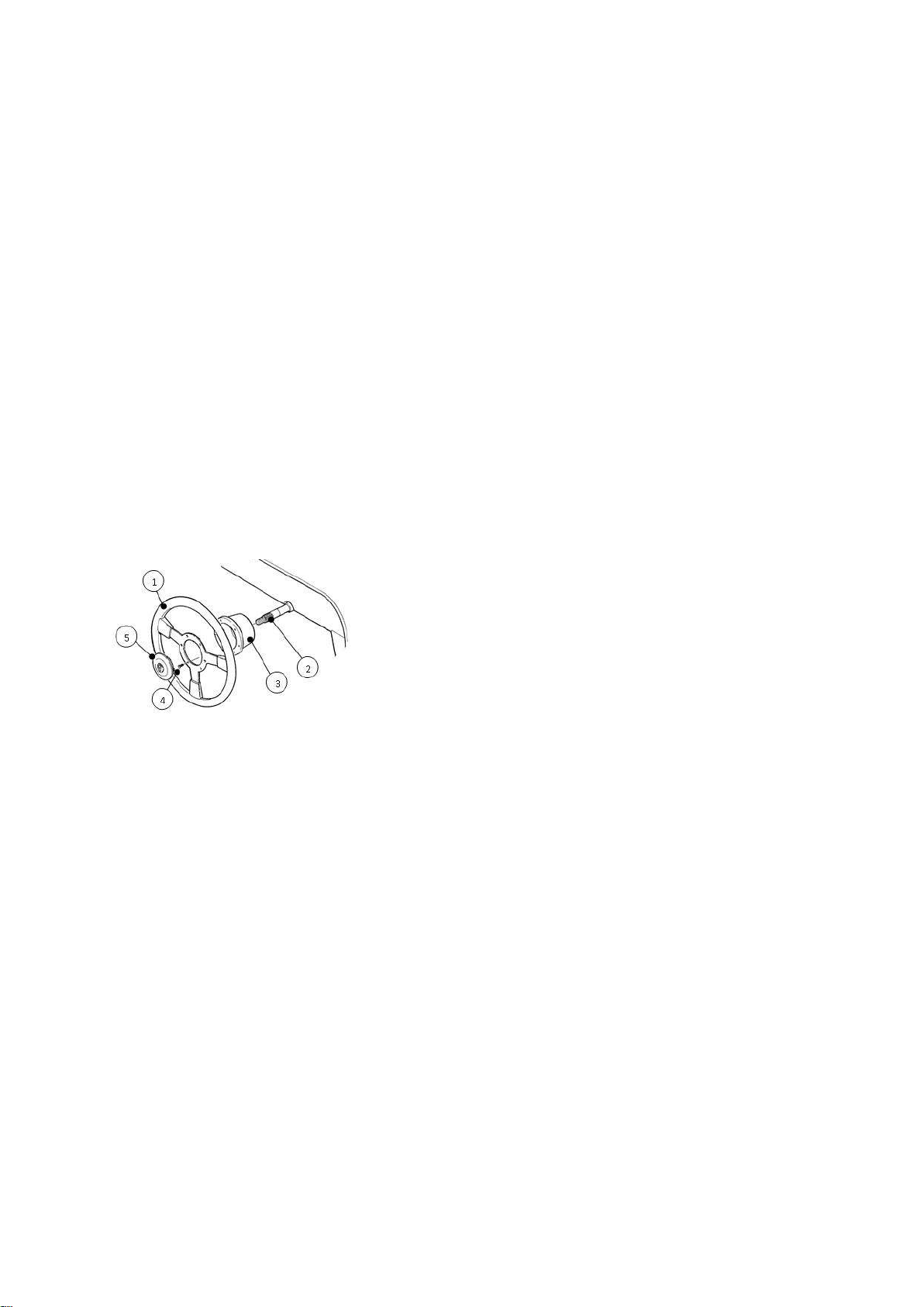
1. Steering wheel
4. Fixing screw
2. Steering column
5. Wheel centre
3. Mounting boss
Figure 28: Steering Wheel - Motolita
4.3) Steering wheel fitment
Two makes of steering wheel are
available. Both the Motolita and the Momo
wheel have a horn button mounted on the
dashboard. Each steering wheel has a
different type of mounting boss. It is
recommended that the fitting of the
steering wheel is left until the entire
interior trim, including seats, has been
completed.
4.3.1) Motolita
4.3.2) Momo
Loosely fit the mounting boss to the
steering wheel using the 6 mm x 16 mm
countersunk Allen bolts. Centre the road
wheels to establish the straight ahead
position of the steering wheel. Place the
steering wheel and boss over the splines
in the straight ahead position. Remove
the wheel and secure the boss to the
column using nyloc nut (4) and washer
(9). Finally re-secure the wheel to the
boss using the fixing provided.
4.3.3) Quick release column
(IVA pad omitted for clarity)
Release steering lock and centre the road
wheels to establish the straight ahead
position. Fit the steering wheel over the
steering column splines. Fit the
The Quick Release (QR) column has a
keyway in the QR boss and the steering
wheel must be centred by removing the
upper bolt on the lower steering column
universal joint, withdrawing the column
and then turning the steering wheel and
column to the straight ahead position. Reengage the column to the universal joint,
re-insert the bolt and tighten the securing
nyloc nut to 20 Nm.
Ensure that the steering wheel can be
rotated smoothly with no tight spots.
Tighten the steering rack clamp bolts and
steering column universal joint
washer (9) and secure the steering wheel
to the steering column using nyloc nut (4)
and tighten.
bolts/nylocs to the torque figures specified
in Table 12.
Page | 55
Page 57

Location
Washers
Nut Torque
Steering rack
clamps
Plain under
bolt head
Nyloc 11 Nm
Universal
joint
None
Nyloc 20 Nm
Column
clamp
Spring and
plain under
bolt head
Bolt 14 Nm
Table 12: Steering component torque
figures
4.4) Associated tasks
Whilst the pedal box lid is removed, fit the
brake light switch harness and the throttle
cable.
NOTE
Before refitting the pedal box lid, check
that the pedal positions are acceptable
and that the brake switch operates
correctly. Adjust as necessary.
Refit the pedal box lid ensuring that the
brake pipes are not trapped or kinked and
that the ‘P’ clips are secured under the
pedal box lid screws.
Page | 56
Page 58
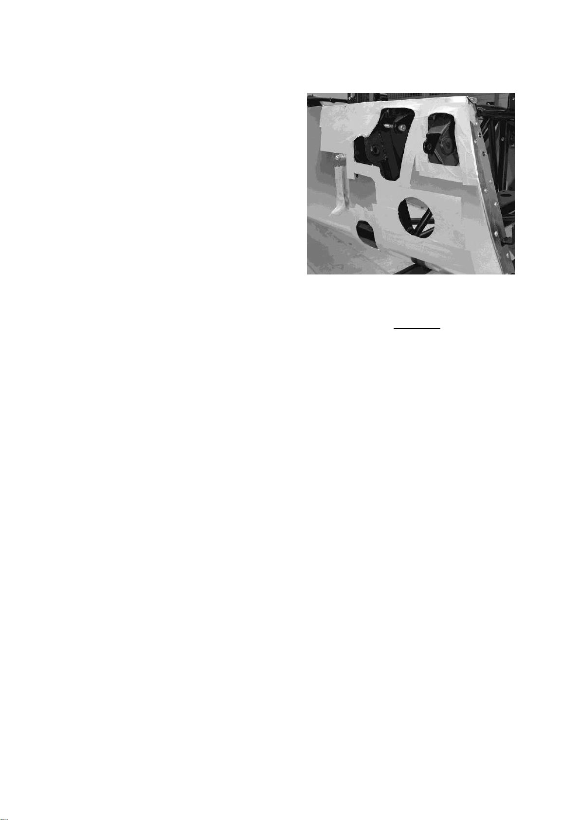
5.0) Front suspension
The following section covers the assembly
and installation of all areas of the front
suspension for your kit.
5.1) Preparation
It is recommended that the front wings are
not fitted until the front suspension is
assembled and the engine installed. This
reduces the risk of damage to the wings
and maintains easy access to the engine
bay.
It is recommended that the steering rack
is fitted before assembling the front
suspension, refer to Section 3.
When assembling the front suspension,
there is a risk that the aluminium body
skin can be damaged, especially when
Figure 29: Bodywork protection
5.2) Lower wishbones
Warning
Never work underneath a car without
supporting it on axle stands or
equivalent. Do not rely on a jack alone.
The lower wishbones are assembled with
the longer leg forward and the bearing
retaining circlip facing downward.
fitting the top mounting bolts and the
spring damper units. It is therefore
advisable, particularly with painted cars, to
protect the bodywork with 2 or 3 layers of
masking tape in key areas. It is
recommended that the bodywork under
the front bonnet catches is protected
using card and masking tape, refer to
Figure 31.
Apply a thin coat of copper grease to all
fixings prior to fitment (avoid
contaminating any threads where Loctite
is to be used).
NOTE
Ensure that the circlip is correctly located
in the retaining groove prior to assembling
the lower wishbone.
Fit the rear leg of the lower wishbone
through the slot in the bottom skin
immediately behind the vertical chassis
member. Secure using bolt (Fastener
pack 30F015A Item 1) and nut (7) and
inserting two plain washers (9) either side
of the wishbone refer to Fig 32.
Page | 57
Page 59
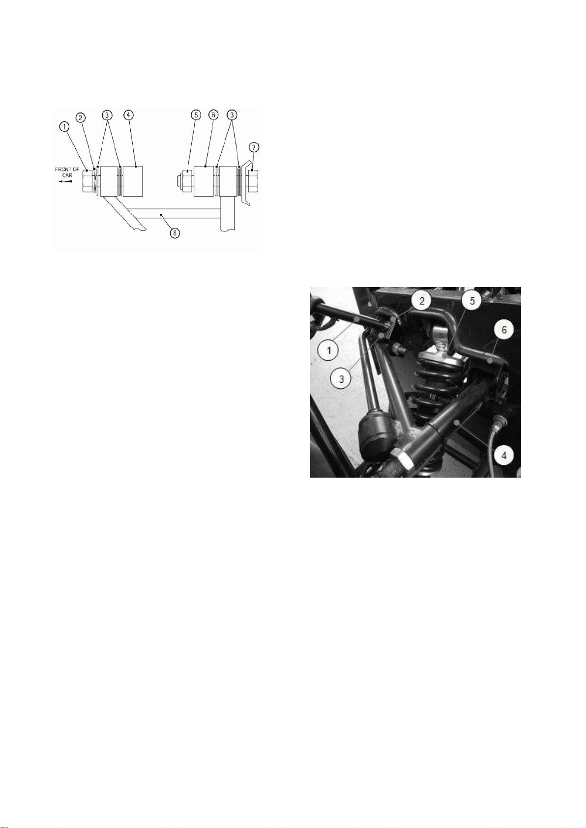
1. Bolt
5. Nyloc nut
2. Spring washer
6. Rear chassis mount
3. Plain washer
7. Bolt
4. Front chassis
mount
8. Lower wishbone
1. Headlight bracket
4. Upper wishbone
2. Headlight bracket
mounting
5. Spring damper unit
3. Upper wishbone
front mount
6. Upper wishbone
rear mount
Figure 30: Washer usage - lower
wishbone (LH side)
OD x 35 mm (polythene bag marked 'front
suspension'), must be inserted into the
rear bush. The rear leg of the upper
wishbone, refer to Figure 33, is secured to
the rear mount using bolts (3) inserted
from the front of the mounting. The
spacer bush must be coated with copper
slip. The bolt is secured with a nut (8).
Do not tighten fixings.
Figure 31: Upper wishbone securing
The front leg of the lower wishbone is
secured to the front of the chassis using
bolt (2), with washer (9) and spring
washer (12) next to the bolt head. Two
washers (9) are inserted between the
wishbone and the chassis, refer to Figure
32.
On wide track models there should be no
washers between the front mount and the
chassis and 4 washers between the
chassis tube and the rear mount of the
lower wishbone.
The front leg of the upper wishbone is
secured to the front mount using bolt (4).
5.3) Upper wishbones
The upper wishbones are handed and are
assembled with the longer leg facing the
front of the car. Prior to locating the upper
wishbone a spacer bush 10 mm ID x 1/2"
Prior to inserting the bolt the headlight
bracket must be inserted over the chassis
mount. Before fitting the headlight bracket
assemble the headlight assembly to the
bracket see page 164.
Page | 58
Page 60

Ensure to fit a rubber grommet in the hole
in the bracket before assembly.
Since access to the upper and lower
wishbone mountings are restricted by
other components installed later in the
build process the mounting fasteners must
be fully tightened at this point. Hold the
wishbones horizontal and tighten the
upper wishbone mounting bolts/nuts to 34
Nm and the bottom wishbone to 81 Nm.
NOTE
Check that there is an equal amount of
exposed threads between the locknut and
ball joint, this should be adjusted to eight
An aluminium spacer 8 mm id x 1/2”
od x 32 mm must be coated in copper slip
and inserted into the lower mounting bush
of the spring damper unit. The spring
damper unit is secured using an M8
caphead bolt (supplied in wishbone) which
passes through the rear leg of the lower
wishbone through the aluminium spacer
bush and into a captive thread on the front
leg. This bolt should be torqued to
20 Nm.
NOTE
Do not tighten any other fixings at this
stage
threads for normal road use
5.4) Spring damper units
An aluminium spacer bush 8 mm id x 1/2”
od x 32 mm (polythene bag marked ‘front
suspension’) must be coated in copper
slip and inserted into the top mounting
bush of the front spring damper unit. The
spring damper is secured to the top
mounting by the M8 cap head bolt
supplied in the chassis with a spring
washer (13) under the bolt head. This bolt
should be torqued to 20 Nm.
NOTES
It is necessary to gently press the body
5.5) Upright attachment
Warning
Correct use of fixtures is required to
ensure full engagement of the nyloc
nut.
Remove and retain the upper wishbone
ball-joint nyloc nut and the nyloc nut from
the bottom of the upright assembly. The
upright assembly must be mounted with
the steering arm facing forward. Mount
the upright assembly as follows:
NOTE
The upright assemblies are marked RHS
or LHS on the inside of the assembly.
panel inwards to allow sufficient clearance
for the bolt to be located.
Page | 59
Page 61

5.5.1) Standard
The upright is located into the spherical
joint on the lower wishbone and secured
using the retained 1/2” nyloc nut. Tighten
the nyloc nut to 55 Nm.
Warning
Correct use of fixings is required in
order to ensure full engagement of the
nyloc nut.
5.5.2) Wide track
The upright is located into the spherical
joint on the lower wishbone. Prior to
locating the upright, a spacer located in
Pass the top wishbone ball-joint down
through the top of the upright and through
the wingstay. To fully engage the tapers of
the wishbone and ball-joint, fit the M14
plain nut (6) from the fastener pack, apply
pressure to the top of the ball-joint and
tighten the plain nut. Once the ball-joint is
locked in place remove the plain nut and
replace it with the nyloc supplied on the
ball-joint. Tighten the nyloc nut to 54 Nm.
Tighten the inner stub axle nut to 82 Nm
and ensure that the upright turns freely on
the wishbones.
Remove and retain the nyloc nut from the
the polythene bag marked ‘front
suspension’) must be inserted onto the
bottom of the upright. The upright is
secured using the special turned down
nyloc nut supplied. Tighten the special
nyloc nut to 55 Nm.
The cycle wingstay locates on the upright.
Remove and discard the 1/2” UNF nyloc
nut and plain washer fitted to the inner
end of the stub axle. Place cycle wingstay
over the stub axle and secure using the
1/2” UNF nyloc provided. Do not tighten.
NOTE
track rod end. Remove and discard the
hard plastic boot protector from the track
rod end taper and pass the tapered shaft
down through the steering arm on the
upright, secure with the nyloc nut. Tighten
nyloc nut to 34 Nm.
Your front suspension should now
resemble that shown in Figure 34. (IVA
covers not shown)
If uprated front brake callipers have been
specified ensure that the brake pads are
installed before fitting the cycle wingstays.
Page | 60
Page 62
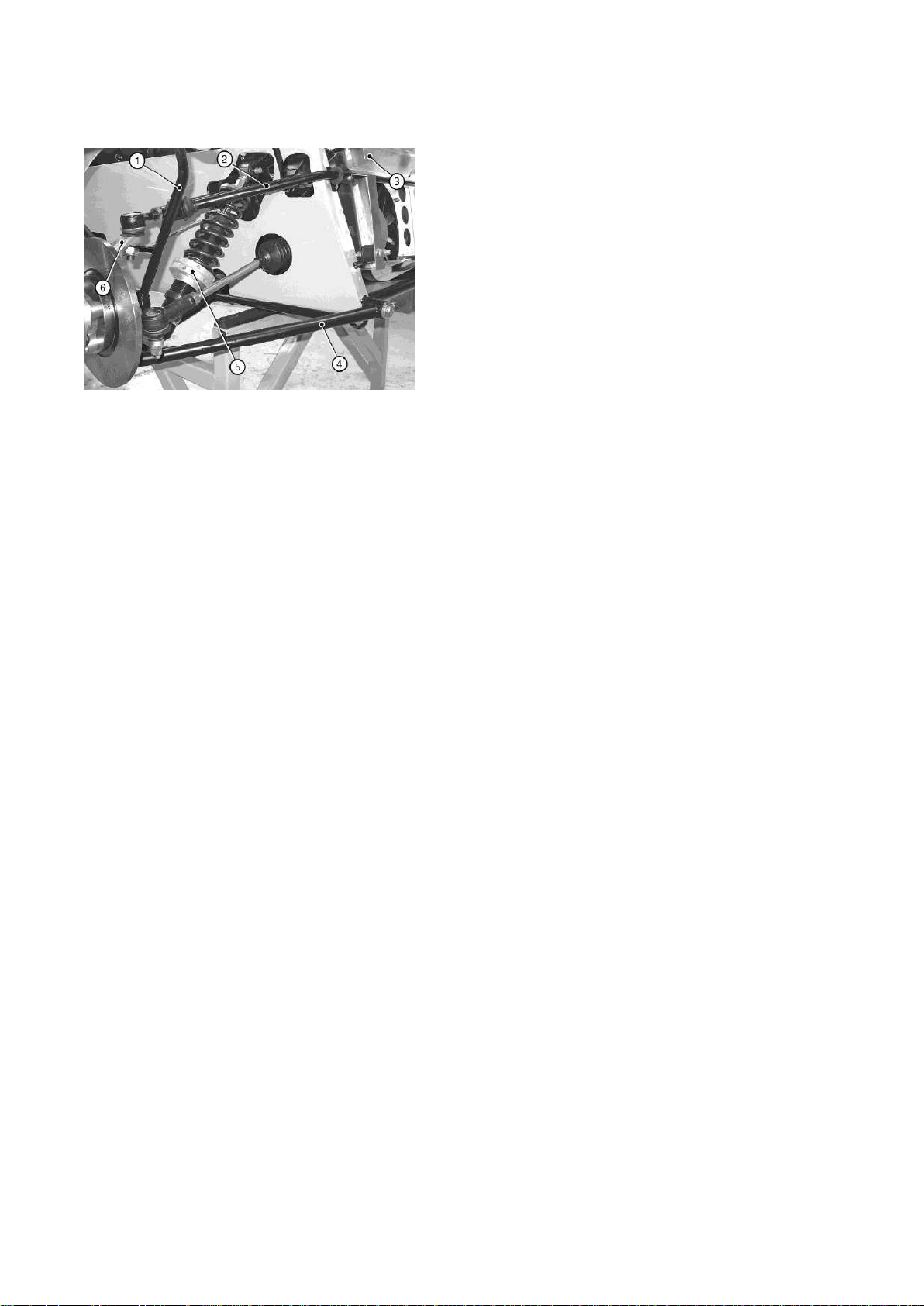
1. Cycle wingstay
4. Lower wishbone
2. Anti-roll bar
5. Spring damper unit
3. Inner radiator
cowl
6. Upright assembly
Figure 32: Front suspension
5.6) Front anti-roll bar
and around so they will align with the
holes drilled in the front face of the
chassis tube.
The rubber boots should be slid over the
anti-roll bar, ensuring that the larger
diameter of the rubber boot is outboard.
Apply Loctite to the threads at each end of
the anti-roll bar and fit the plastic balls,
tighten using protected grips.
Liberally coat the balls with bearing
grease. Assemble the anti-roll bar onto
the chassis by pushing the plastic balls,
one at a time, into the mounting cups in
the upper wishbones. Fit the spring
Notes
(1) On Seven 420 the inner radiator cowl is
located inboard of the anti-roll bar and must be
fitted first, refer to section 6. Seven 270 &
Academy do not have radiator cowling.
(2) Check that the colour of the bushes
corresponds to the colour marked on the
front anti-roll bar.
The anti-roll bar is attached to the front of
the chassis using the special mounting
brackets and cotton reel shaped bushes
(supplied in the polythene bag marked
‘front suspension’). Liberally coat the
washers (13) to the bolts (5) and pass
forward through the vertical chassis tubes
and into the captive nuts on the mounting
brackets. Tighten to 20 Nm.
The rubber boots are slid over the
mounting cups and secured to the top
wishbone using cable ties which fit into
the grooves provided. A further cable tie
is used to hold the boot onto the anti-roll
bar itself with the tails of the cable tie
being cut off underneath for neatness.
NOTE
All connections should initially be made
finger tight
bushes with rubber lubricant and fit the
bushes into the brackets. Slide the
brackets over the ends of the anti-roll bar
Page | 61
Page 63
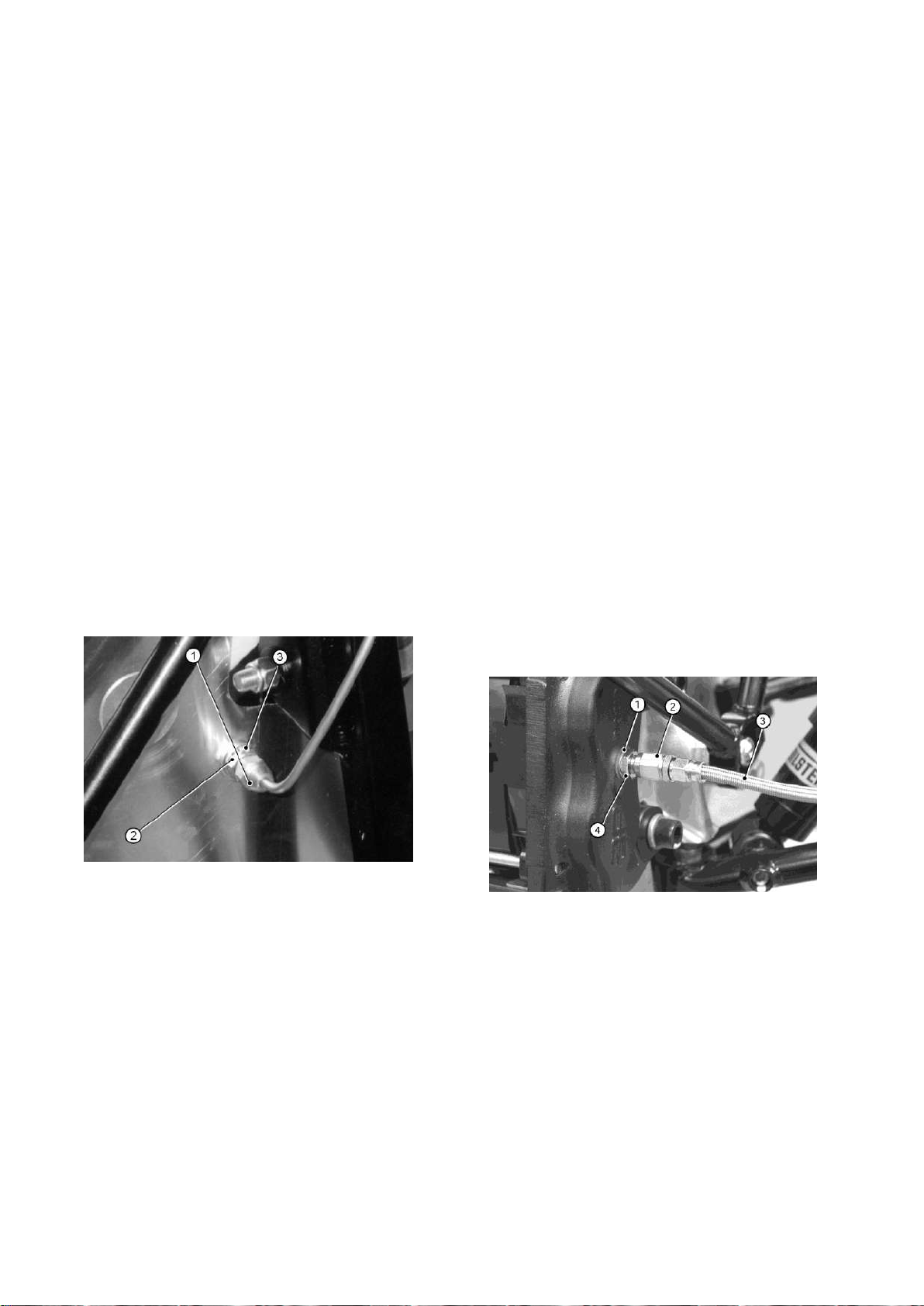
1. Female pipe union
3. Shakeproof washer
2. Plain washer
1. Copper washer
3. Braided brake hose
2. Female union
4. Adaptor
5.7) Front brake hoses
Three stainless steel braided brake hoses
are supplied, two of equal length for the
front brakes and one of longer length for
the rear brakes.
Attach the inner, threaded end of each
brake hose through the hole in the
aluminium body. A plain washer (fastener
pack 30F015A item 11) should be fitted
directly next to the aluminium body on the
outside. Secure using the 3/8” nut and
shake proof washer (14). The shake
proof washer must be between the nut
and the inside panel. Do not tighten.
5.1.2) Standard & Uprated calliper
On the standard and uprated calliper, the
braided brake hose has a female union at
the calliper end, refer to Fig 36. The
braided hoses are supplied with an
adaptor that screws into a threaded
drilling inboard of the calliper body. The
adaptor must be fitted with the tapered
end outward, this provides the seal
between the adaptor and the braided
brake hose female union, and a copper
washer between the adaptor and the
brake calliper. The female union on the
braided hose screws directly to the
adaptor. Do not over tighten. Torque to
Figure 33: Brake pipe union
The outer end should be attached to the
brake calliper as follows:
25 Nm.
Figure 34: Standard & Uprated calliper
Located on the inside of the body are the
female unions, refer to Fig 35, on the end
of the brake pipes from the brake master
cylinder. Fix the female union to the
braided brake hose connection and
Page | 62
Page 64

Location
Washer
Torque
Sub axle
81Nm
Damper to lower
wishbone (lower
fixing)
N/A
20Nm
Damper to
chassis (top
fixing)
N/A
20Nm
Front anti-roll bar
fixing
Spring under
head
20Nm
Upright top balljoint
None
54Nm
Upright – bottom
Spacer – wide
track only
54Nm
Location
Washer
Torque
Upper wishbone
34Nm
Lower wishbone
front
Spring under
head then plain
as shown in
Figure 2.
81Nm
Lower wishbone
rear
Plain spacers as
shown in Figure
2.
81Nm
tighten to 10 Nm. Tighten the locknut to
10 Nm.
Turn the steering from lock to lock and
ensure that the braided brake hoses do
not foul on the suspension. If fouling is
observed remove the braided brake hose
from the calliper and twist the hose
through 180. Refit the braided brake
hose to the calliper and tighten unions to
10 Nm.
5.8) Final tightening
All the remaining fixings should be
tightened according to Table 13.
Table 13: Front suspension torque
Figures
5.9) Cars fitted with adjustable damper
platform
Cars fitted with adjustable damper
platforms need to be adjusted to achieve
the optimum ride height. This is done by
lowering or raising the height of the
platforms on the threaded sleeve. It is
essential that this task is carried out on
level ground.
Page | 63
Page 65

NOTE
Lowering the platforms will decrease ride
height, and raising the platforms will
increase ride height. For the best results
the ride height should be set with the
driver in the car and fuel in the tank.
1. Start by adjusting the front dampers to
achieve a minimum distance of 150 mm
(this can be increased for road use to a
maximum of 190 mm) between the ground
and the bottom of the lower chassis rail,
where the rear leg of the front lower
wishbone exits the side of the car. This
measurement should be the same on both
sides with the car loaded.
2. Now adjust the rear dampers in the
same manner to achieve a height 15 mm
higher than the front, measured to the
underside of the lower chassis rail
immediately in front of the 'A' frame
mounting point.
NOTE
Adjusting the rear may have an effect on
the front therefore it is good practice to
check between front and rear several
times during adjustment
3. Once the desired ride heights have
been set ensure that the platforms are
locked together to avoid movement.
Page | 64
Page 66
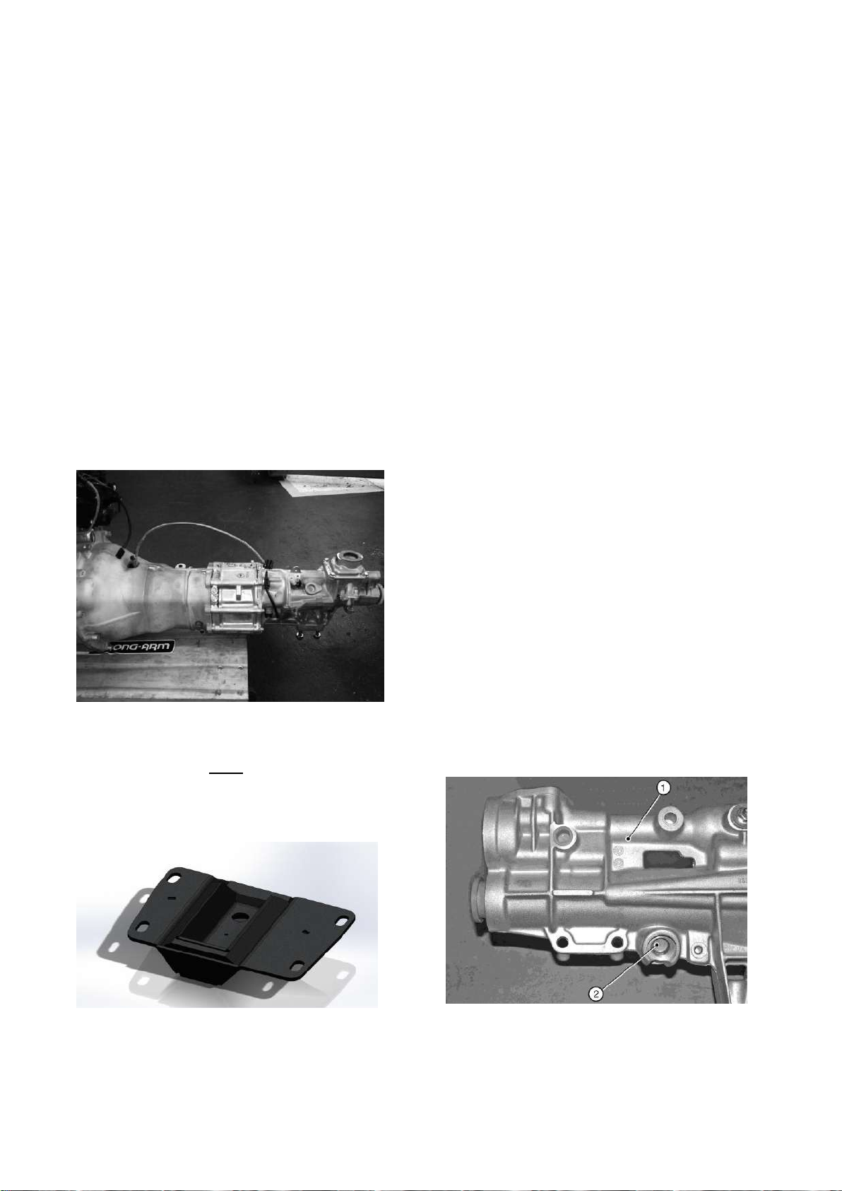
1. Gearbox
2. Plug
6.0) Fitment of gearbox to engine
6.1) Assembly of gearbox kit.
To assemble the gearbox to bell-housing,
proceed as follows:
5-Speed. There are no gaskets on this
gearbox either between the gearbox and
bell-housing or the bell-housing and
engine. Bolt the gearbox to the bellhousing using the 4M12x70 bolts with a
plain washer from the inside. Tighten bolts
to 47Nm.
6-Speed Apply a thin layer of silicone
sealant to the front face of the gearbox
and to the 'O' ring around the selector rod.
Ensure sealant is applied to the entire 'O'
ring. Seven 270: Using the four cap-head
bolts (fastener pack 36G006A Item 9) and
spring washers (12), bolt the bell-housing
to the gearbox from the inside. Tighten the
bolts to 47 Nm. (The bell housing is
loosely fitted to the engine for transport).
Seven 360/420: Do not remove bellhousing. Using 4 M10x35 bolts with
spring and plain washers supplied in the
gearbox pack bolt from the outside and
torque to 35Nm.
Unlike the 6-speed, the gearbox mount
can only be fitted after the engine and
gearbox are in the car and before the
engine mounts are fitted.
NOTE
Loosen gearbox filler plug.
All Duratec models have the bellhousing
pre-fitted to the engine, so fixing pack
36G006A is not required.
Figure 35: Speedo shaft plug – 6 speed
Page | 65
Page 67
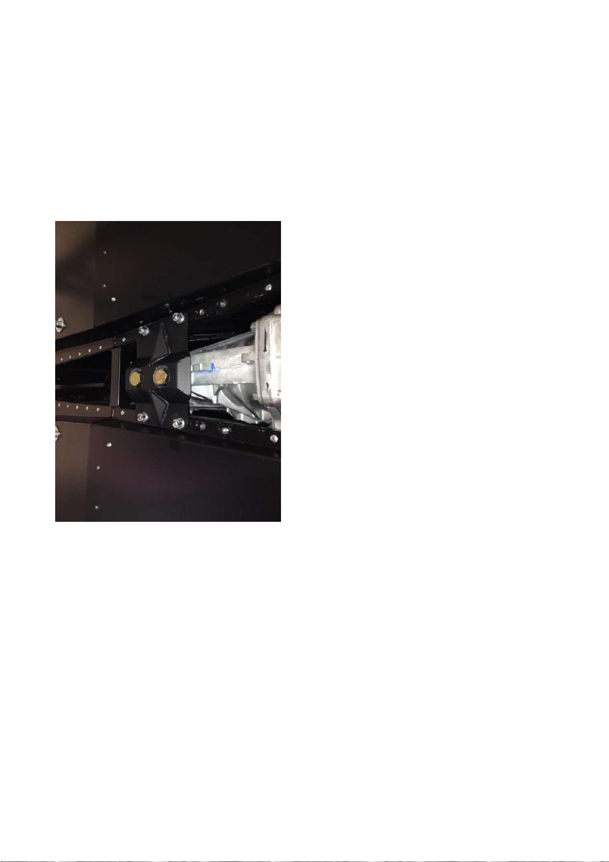
Bolt the metal/rubber/metal gearbox
mounting, chamfered edge forward, refer
to Fig 39, to the underside of the tailshaft
housing using one bolt (8) and spring
washer (12). Tighten to 61 Nm.
New 2014 5 speed Caterham gearbox.
6.2) Fitting gearbox to engine
Slide the gearbox into place on the rear of
the engine. It may be necessary to rotate
the gearbox assembly in order to line up
the gearbox first motion shaft splines with
the splines of the clutch plate.
5-speed - Bolt the bell-housing to engine
from the front of the engine looking back
from the top right going clockwise
M10x40, M10x55,M10x55,M10x60,
M10x45, M10 x55 and M10x40 all with
spring washers. Tighten to 35Nm
6 speed - Using the fixings supplied,
The gearbox mount can only be fitted
once the engine and gearbox are in the
car and before the engine mounts are
fitted. Using 2 M14x40 bolts with a plain
washer and thread lock bolt the mount to
the gearbox, with the cut out facing the
front, tighten to 40Nm,
connect the engine and gearbox; two bolts
(2) and spring washers (10), pass forward
from the top of the bell-housing into the
cylinder block, two more bolts (2) and
spring washers, pass forward from the
bottom of the bell-housing into the sump.
Two bolts (1) and spring washers pass
rearward through the 'ears' on the engine
assembly and into the bell-housing on the
RH side, one further bolt (1) and spring
washer passes forward from the LH side
of the engine into the bell-housing.
6.3) Starter motor
Install the starter motor into the front of
Using 4 M8x40 caphead bolts with a plain
washers and nyloc bolt the mount to the
chassis, tighten to 20Nm, bolts can be
found in pack 3EZ1105
the bell-housing and secure with three
M10x60 (5 speed) or M10x55 (6-speed)
cap head bolts and spring washers.
Page | 66
Page 68

Fixing
Torque
Bell housing to gearbox
47Nm
Gearbox rubber mounting to
tailshaft housing
61Nm
Engine to bell-housing
47Nm
Bell-housing to sump
20Nm
Starter motor
34Nm
Item
Description
Engine hoist and sling
SWL of 150 Kg
(min)
Tighten all starter motor and bell-housing
the bolts to the torques specified in Table
14.
Table 14: Gearbox torque figures
7.0) Installation of engine and
gearbox
The following section details the
installation of the engine and gearbox for
your kit. The engines are detailed
separately. Please refer to the relevant
section.
7.1) Sigma engine
7.1.1) Preparation
The special tools detailed in Table 15
bellow will be required for this section.
Table 15: Special tools required for
sigma engine
7.1.1.1) Screen wash/wipe
NOTE
The bracket for the washer bottle must be
fixed to the front of the passenger side
foot box before the engine is installed.
Remove the securing nut from the base of
the washer jet and pass the washer jet
through the hole in the centre of the
scuttle and secure with the plastic
securing nut. Fit the clear plastic tubing to
the washer jet. Dip the end of the clear
plastic tubing in hot water to soften in
order to make fitting easier.
Page | 67
Page 69
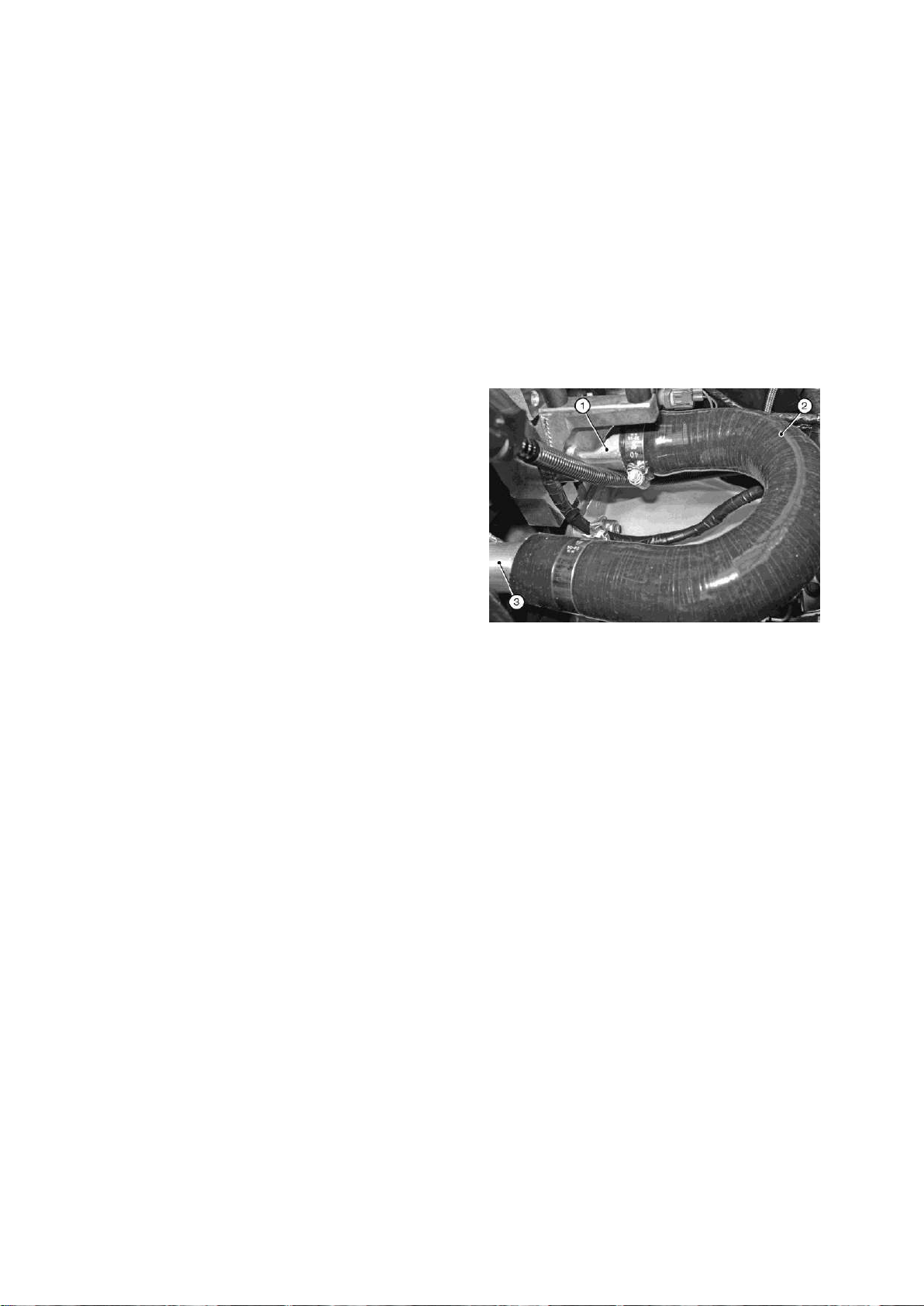
1. Engine connection
2. ‘U’ hose
3. Water rail
Route the clear washer tubing along the
wiring loom behind the dashboard and
attach using cable ties, to prevent it falling
down into view. Pass it down through the
large grommet in the top of the
transmission tunnel and along the engine
bay diagonal tube until in line with the
washer bottle. Trim the tube to length and
attach to the washer motor.
Connect the washer motor to the wiring
loom via the two pin plug adjacent to the
washer bottle mounting. To ease fitment
of the two pin plug the washer motor can
be removed from the washer bottle, the
outlet located on the rear of the cylinder
head, and the rear aluminium water rail,
you will need to cut this pipe to length,
refer to Figure 41. Apply rubber lubricant
to the ends of the hose and push over the
outlets; Secure using a hose clip
(Fastener pack 'cooling' 30C047A).
Figure 36: Water rail and 'U' hose
two pin plug fitted and the washer motor
reinserted into the washer bottle.
The windscreen wipers must not be
fitted until the wiper motor has been
run and allowed to park in order to
prevent damage to the paintwork. Fit the
wiper arms so that they are horizontal
when parked. The wiper arms must move
smoothly through their range of travel.
NOTE
A small amount of water splashed on the
windscreen will prevent the wiper blades
Remove and retain the gearbox filler plug.
Removal of this plug is not essential;
however access is restricted within the
confines of the transmission tunnel. It is
easier to fill the gearbox up before you put
it into the car. Remove the plastic plug
from the gearbox tailshaft housing once
the engine and gearbox are in the
chassis, the plug will hold the oil in the
gearbox while you fit it.
from juddering during test and adjustment
7.1.1.2) Engine preparation
The large diameter pre-formed 'U' hose
should be fitted onto the aluminium water
7.1.1.3) Chassis preparation
Protect the appearance of the engine bay
chassis tubes and pedal box sides and
Page | 68
Page 70
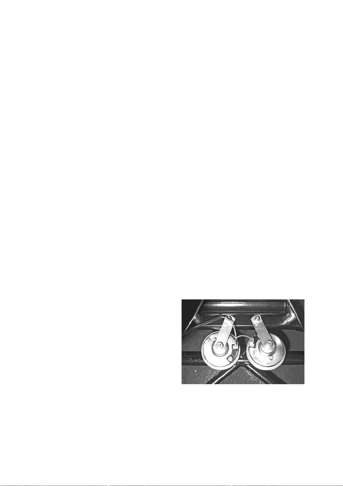
edges by covering with card and/or
masking tape.
Ensure that all wires and connector plugs
are secured and will not snag or catch the
engine/gearbox as it is lowered.
NOTE
Before fitting engine mounting rubber
blocks ensure that the large threaded
(1/2" UNF) boss in the centre is clear of
rubber and that the bolt will thread in
cleanly.
Fit the engine mounting rubber block to
the RH side of the engine bay. The two
rear hole of the engine mounting block,
through the chassis and secure with
nyloc (9) and plain washer (12). Do not
tighten. (Other end of the earth lead
needs to be connected to engine through
engine mount after engine installation).
Locate the twin electric horns on the two
studs near the rear edge of the steering
rack platform. Before fitting the horns,
loosen the 13 mm nut in the centre of
each horn, this will allow rotation of the
horns so that the electrical connections
are closer together.
Secure the horns with the nyloc nuts
bolts (fastener pack 30P012A Item 3),
plain washer (12) are passed downwards
through the mounting, through the chassis
and are secured with nyloc nuts (9) and
plain washers (12). Do not tighten.
Fit the engine mounting rubber block to
the LH side of the engine bay, locate the
engine earth lead (a black earth lead
approximately 300 mm long supplied
loose in a box), pass bolt (2) and washer
(12) downwards through the lead, through
the front hole of the engine mounting
block, through the chassis and secure
with nyloc nut (9) and plain washer (12).
(fastener pack 30P012A item 10) and
ensure that it is not possible for the horns
to come into contact with each other, the
steering rack or other components in the
engine bay refer to Figure 42.
Figure 37: Horn location
Remove a little paint from the
chassis/mounting to ensure that a good
electrical contact is made. Pass bolt (3),
plain washer (12) downwards through the
Tighten the 13 mm nut in the centre of
each horn and connect the horns to the
electrical harness by the purple and
yellow wires and connectors located
Page | 69
Page 71
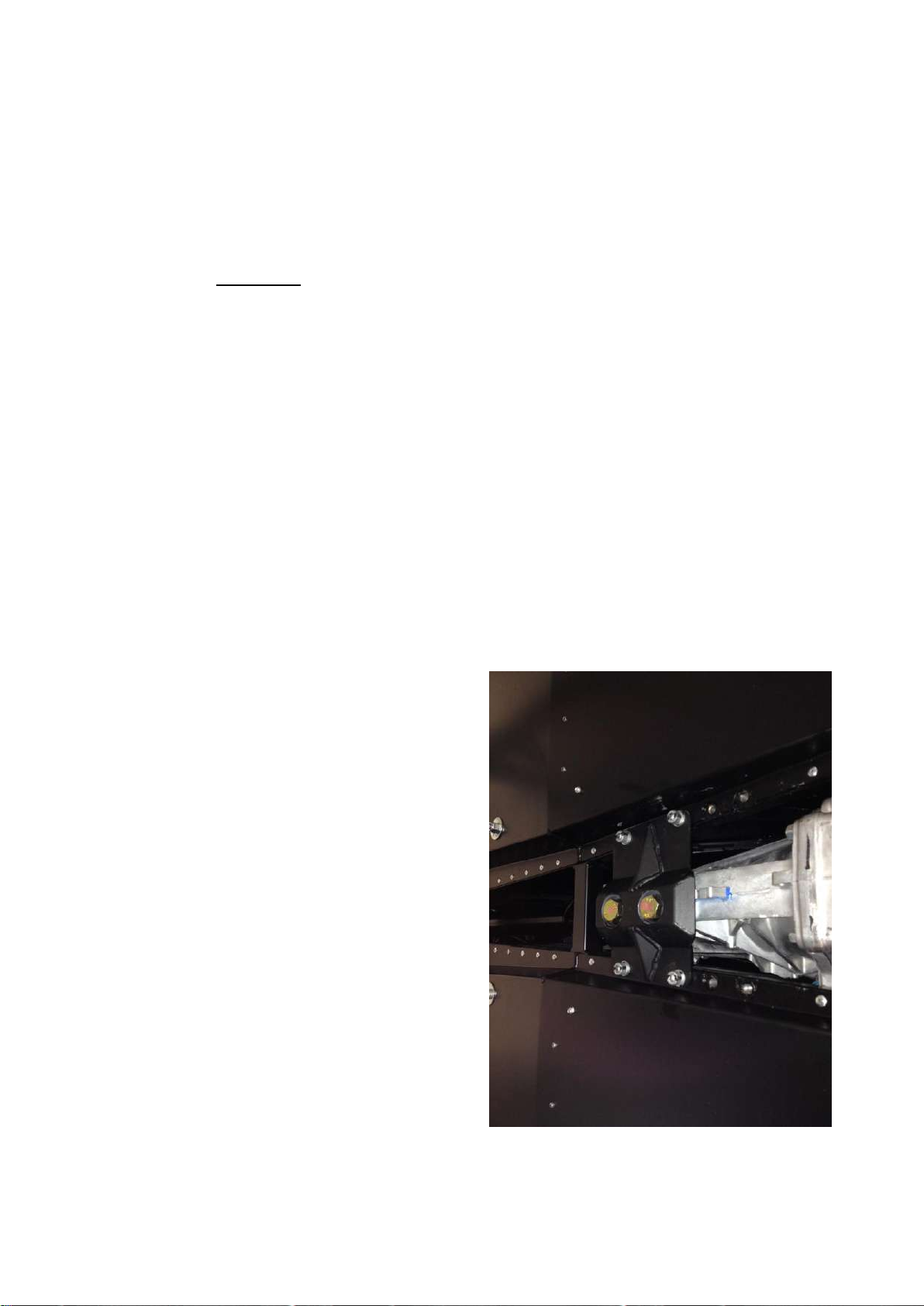
above the horns on the front upper cross
member.
7.1.2) Installation of engine/gearbox into
chassis
Warnings
1. Never work underneath a car without
supporting it on axle stands or
equivalent. Do not rely on a jack alone.
2. Use appropriate eye protection
whilst working under the car.
3. Care should be taken while dropping
the engine into the chassis to avoid
any damage to engine component or
wiring.
Using the lifting hoist and sling detailed in
Attach the LH engine mounting using the
two M8 x 25 mm bolts (fastener pack
36G006A Item 4) and one M8 x 30 mm
bolt (5), use spring washer item (11) for
each bolts. Connect the other end of the
earth lead through one of the engine
mount fixings. Do not tighten the bolts.
Attach the RH engine mounting using the
two M8 x 35 mm bolts (6) and two M10 x
40 mm bolt (2),use spring washer item (10
& 11 ) for each bolts, Do not fully tighten
the engine mounting retaining bolts until
advised later in this section.
For cars equipped with a 5-speed
gearbox, the gearbox mount should now
be fitted.
Table 15, attach the engine/gearbox using
the lifting eyes provided on the engine,
lower the engine/gearbox assembly into
the engine bay at an angle of between 3040 (with the engine higher than the
gearbox). Insert the gearbox assembly
into the transmission tunnel.
Continue to slide the engine/gearbox
rearward until the holes in the gearbox
mounting line up with the holes in the
chassis cross member. If the differential
and propshaft have already been fitted,
ensure that the propshaft locates into the
gearbox tailshaft housing.
Page | 70
Page 72

Fixing
Torque
Engine mounting to block
25Nm
Engine mounting to mounting
rubbers
41Nm
Engine mounting rubbers to
chassis
20Nm
Gearbox mounting rubber to
chassis
20Nm
Lower the engine onto the rubber engine
mountings. Using 2 M14x40 bolts with a
plain washer and thread lock bolt the
mount to the gearbox, with the cut out
facing the front, tighten to 40Nm,
Using 4 M8x40 caphead bolts with a plain
washers and nyloc bolt the mount to the
chassis, tighten to 20Nm, bolts can be
found in pack 3EZ1105
At the engine mounts, pass the bolts
(fastener pack 30P012A Item 1 (LHS) and
21 (RHS)) down through the tube on the
outer end of the engine mounting
brackets. Screw the bolts loosely into the
threaded bush in the centre of the rubber
engine mounting. It is recommended that
washer (12) and nyloc nut (9) on each bolt
and tighten to 20 Nm.
Finally tighten the fixings detailed in
Table 16.
Table 16: Gearbox installation torque
figures for sigma engine
the engine is not removed from the hoist
until all the bolts have been tightened
(detailed later in this section).
Adjust the gearbox on its slotted
mountings to achieve equal clearance
within the transmission tunnel. This must
be checked carefully as clearances are
tight and poor alignment can cause the
gearbox to contact the chassis under
cornering.
Bolt the gearbox mounting rubber to the
chassis using bolts (fastener pack
30P012A Item 4) passed down through
the outer metal part of the rubber
mounting and then through the elongated
holes in the chassis. Secure with a plain
NOTES
1. It is now safe to remove the engine
hoist.
2.Wiring – Every effort is made to clearly
explain and identify all the electrical
connections as you go through this
section; however the loom fitted to your
car may have additional wires and
connectors that are not required on your
vehicle. To help clarify this, a wiring
diagram can be found in the electrical
section.
5-speed - The reverse light switch has
already been fitted to the gearbox, just
connect the two connectors to the
Page | 71
Page 73
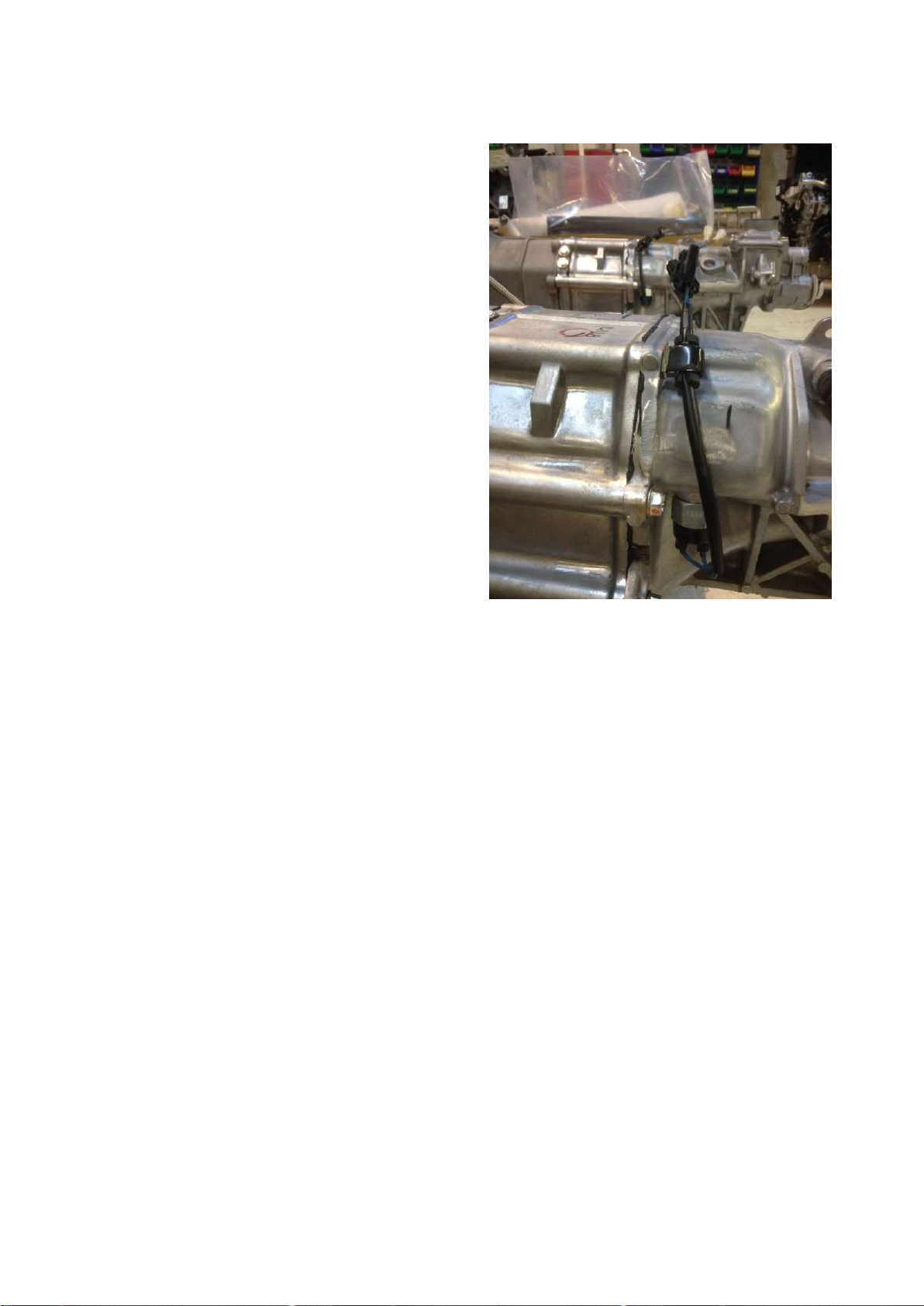
connectors in the main wiring harness in
the tunnel.
The gear lever can only be inserted one
way, make sure the lower bush is seated
correctly and bolt down with 3 M6x12
button head screws to 11NM, these can
be found in 3EZ1105
6-speed - Fit the gear lever to the top of
gearbox tailshaft housing and secure with
three setscrews (7). No washers are
required; tighten to a torque of 20 Nm.
Fit the reverse light switch (polythene bag)
into the side of the gearbox. This can be
in the transmission tunnel.
accessed via the hole in the RH side of
the transmission tunnel. The switch
should be inserted finger tight and then
tightened a further quarter of a turn using
a suitable sized spanner. Connect the
wiring loom to the reverse light switch.
From the cockpit, insert the large grommet
(polythene bag) to cover the access hole
7.1.3) Electrical connections
The engine wiring loom is already
attached to the engine and some
ancillaries, however it is necessary to link
the engine wiring loom to the remaining
ancillaries and the vehicle wiring loom. All
the plastic connecting plugs are matched
pairs so it is not possible to connect them
incorrectly.
Page | 72
Page 74
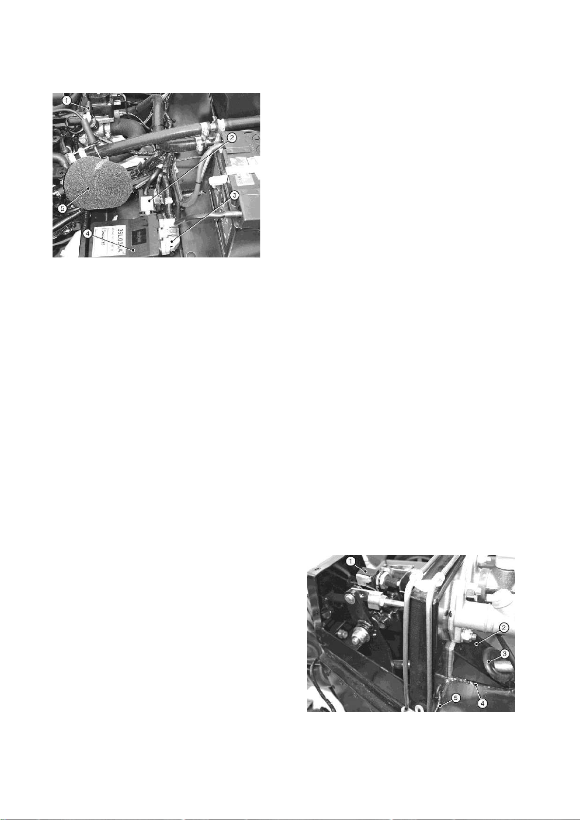
1.Fuel pipe connection
4. ECU
2. MAP unit
5. Air filter
3. Multi-pin plug
1. Brake light switch
4. Sealant
Figure 38: ECU and MAP unit
The ECU and MAP unit are already fitted.
be found clipped to the outside of the
passenger foot box.
The two, paired, black/yellow wires with
ring terminals in the engine loom are earth
connections. Attach both pairs to a
suitable earth point on the bulkhead.
The green, green/purple pair (with
grommet) in the engine loom is for the
brake light switch. The brake light switch
is inside the drivers pedal box and the
harness may be connected during
installation of the steering column. Pass
the brake light switch harness through the
hole in the rear of the pedal box, refer to
Fig 44 and push the two female
Connect the green 3-pin plug on the
engine loom to the connection on the
MAP unit. Connect the short pipe on the
MAP unit to the corresponding connection
on the throttle body using the rubber
vacuum hose provided (Seven 270 &
Academy only).
Connect the black wire from the vehicle
loom to pin 16 in the ECU plug (140 only)
The ECU for the Academy is already fitted
under the battery. The MAP unit is
positioned on the passenger footbox.
Connect the oil pressure switch from the
connectors onto the male connectors of
the brake light switch (orientation is not
important). Fit the grommet into the hole
and ensure that the harness will not foul
the steering column or pedals.
Figure 39: Brake light switch harness
LH side of the engine block to the
connector from the main loom which can
Page | 73
Page 75
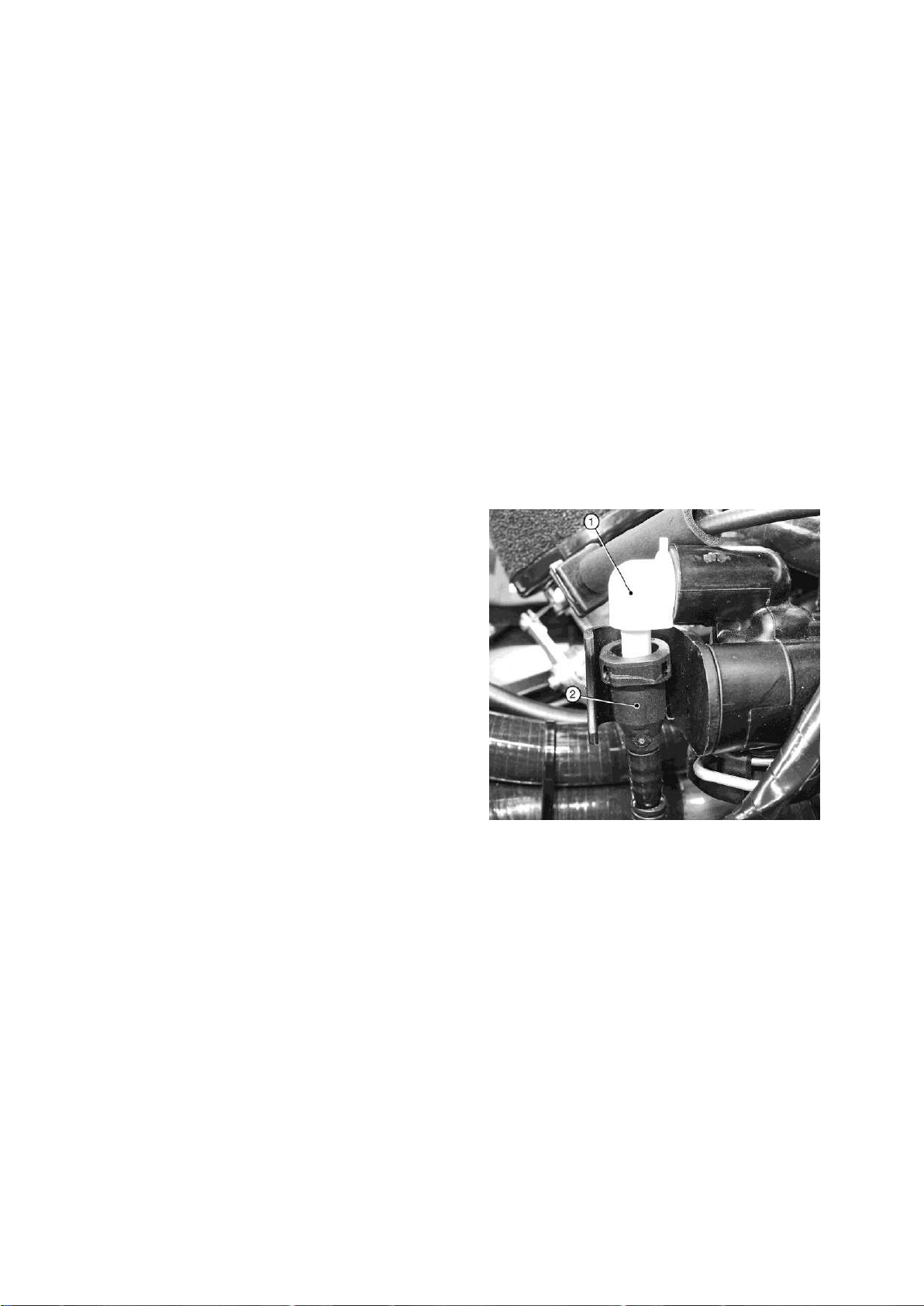
2. Cheese wedge
5. Brake light
3. Grommet
6. Switch harness
1. Fuel rail connection
2. Fuel pipe (from pump)
Make sure the leads are not touching to
any surrounding metal component.
The longest wire from the engine loom
(terminating in a 4-pin plug) is the
7.1.4) Fuel system
connection for the exhaust mounted
lambda probe. This cannot be connected
until the exhaust primary pipes and
collector/catalyst is fitted.
Remove the outermost Bell housing
securing bolt and spring washer. Pass
the Bell housing mounting bolt and
attached spring washer through the black
battery earth lead and secure to the bellhousing. Tighten to 34 Nm.
Connect the red lead from the starter
motor to the battery. Also connect the
black lead on the main vehicle loom to the
The black, corrugated plastic, high
pressure fuel pipe from the fuel pump
emerges from the transmission tunnel and
is a push-fit on the white elbow connection
at the rear of the fuel rail, refer to Fig 45.
Note that there is no fuel return pipe with
this system
Figure 40: Fuel pipe connection
starter motor on the same terminal.
NOTE
If a battery master switch is fitted, there
will be two red leads; one goes to the
battery, the other to the starter. The brown
lead is already connected.
Connect the brown lead from the
alternator to the starter.
Connect the brown/red wire (covered with
black insulation) from the chassis loom to
the starter solenoid.
NOTE
Once fitted the pipe cannot be removed
without a special tool. Ensure that the pipe
is kink free and routed away from possible
snags or chafe points. Remove the red
protective cover and push the connection
on the pipe firmly onto the elbow and
check that it is securely attached. Secure
the pipe with cable ties if necessary.
Page | 74
Page 76
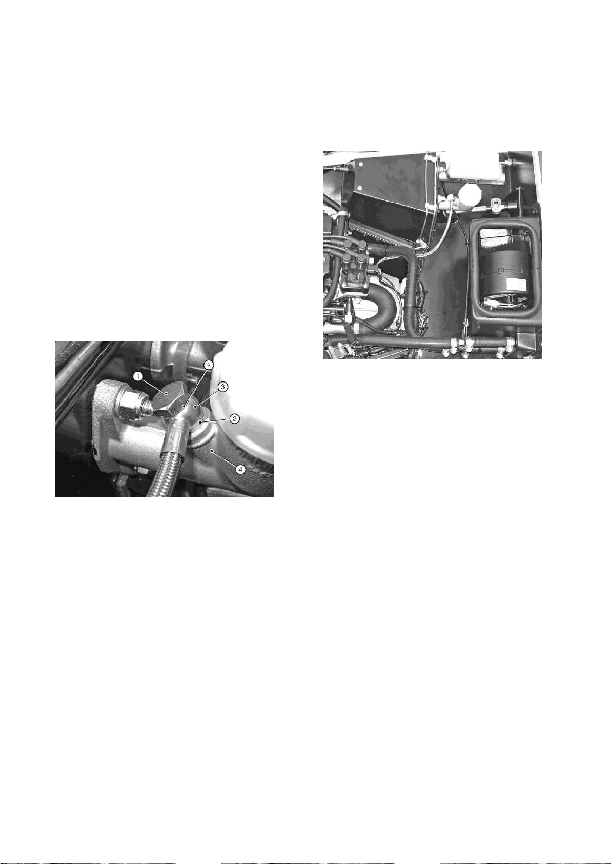
1. Banjo bolt
3. Hose union
2. Copper washers
4. Clutch master
cylinder
7.1.5) Clutch hydraulic hose
Remove all packaging from the clutch
hydraulic hose. Fit a copper washer to the
banjo bolt and pass the banjo bolt through
the union at the end of the hose, refer to
Fig 46. Fit the second copper washer to
the banjo bolt and screw the banjo bolt
into the clutch master cylinder outlet port
(remove the port plug). Do not fully tighten
the banjo bolt.
Figure 41: Clutch master cylinder hose
union
the banjo bolt (the clutch system is filled
and bled during start-up/final checks.
Figure 42: Clutch hydraulic hose
Route the hose down the side of the pedal
box, over the wiring loom (under the
heater hose if fitted) and across the top of
the bell-housing, Refer to Figure 47. Push
the end of the hose into the connector in
the clutch release bearing assembly and
7.1.6) Exhaust systems
The standard exhaust system consists of
four primary pipes, a collector assembly
which also incorporates the catalytic
converter and a one piece silencer and tail
pipe.
Bolt the exhaust mounting bracket
(polythene bag marked 'exhaust') to the
RH side of the car forward of the rear
wheel, using setscrew (fastener pack
30X020A Item 1) and spring washers (3),
refer to Figure 48. Secure the bobbin to
the angle bracket with a nut (2) and spring
washer (3).
ensure that the hose is firmly attached.
Secure the hose with cable ties if
necessary, to prevent chafing and tighten
Page | 75
Page 77

1. Angle bracket
4. Bobbin
2. Spring washer
5. Nut
3. Setscrew
Figure 43: Exhaust mounting
Remove the exhaust gasket and
associated fasteners from the RH side of
the cylinder head, remove any masking
tape protecting the exhaust ports and
clean off any adhesive residue.
The S3 exhaust primary pipes are marked
with their part numbers:
1. Pass the flanged end of # 4 pipe
inwards, attach the flange loosely to the
cylinder head and ensure that the pipe sits
in the bottom LH corner of the aperture
(viewed from outside).
2. Pass the flanged end of # 1 pipe
inwards, attach the flange loosely to the
cylinder head and ensure that the pipe sits
in the top RH corner of the aperture.
3. Pass the plain end of # 3 pipe
outwards, attach the flange loosely to the
cylinder head and ensure that the pipe sits
in the bottom RH corner of the aperture.
4. Pass the plain end of # 2 pipe
outwards, attach the flange loosely to the
cylinder head and ensure that the pipe sits
in the top LH corner of the aperture.
NOTE
36X014A is for # 1 (front) cylinder
36X015A is for # 2 cylinder.
36X016A is for # 3 cylinder.
36X017A is for # 4 (rear) cylinder.
Protect the area around the square
aperture in the side panel with masking
tape and card, place the exhaust gasket
over the remaining studs and fit the
primary pipes in the following sequence:
For SV use the same procedure to fit the
primary, the sequence to fit the primary is
4,3,1,2.
56X005A is for #1(front) cylinder.
56X006A is for #2 cylinder.
56X007A is for #3 cylinder.
56X008A is for #4 (rear) cylinder.
When the primary pipes are in place fit
any remaining fasteners but do not tighten
them.
Page | 76
Page 78
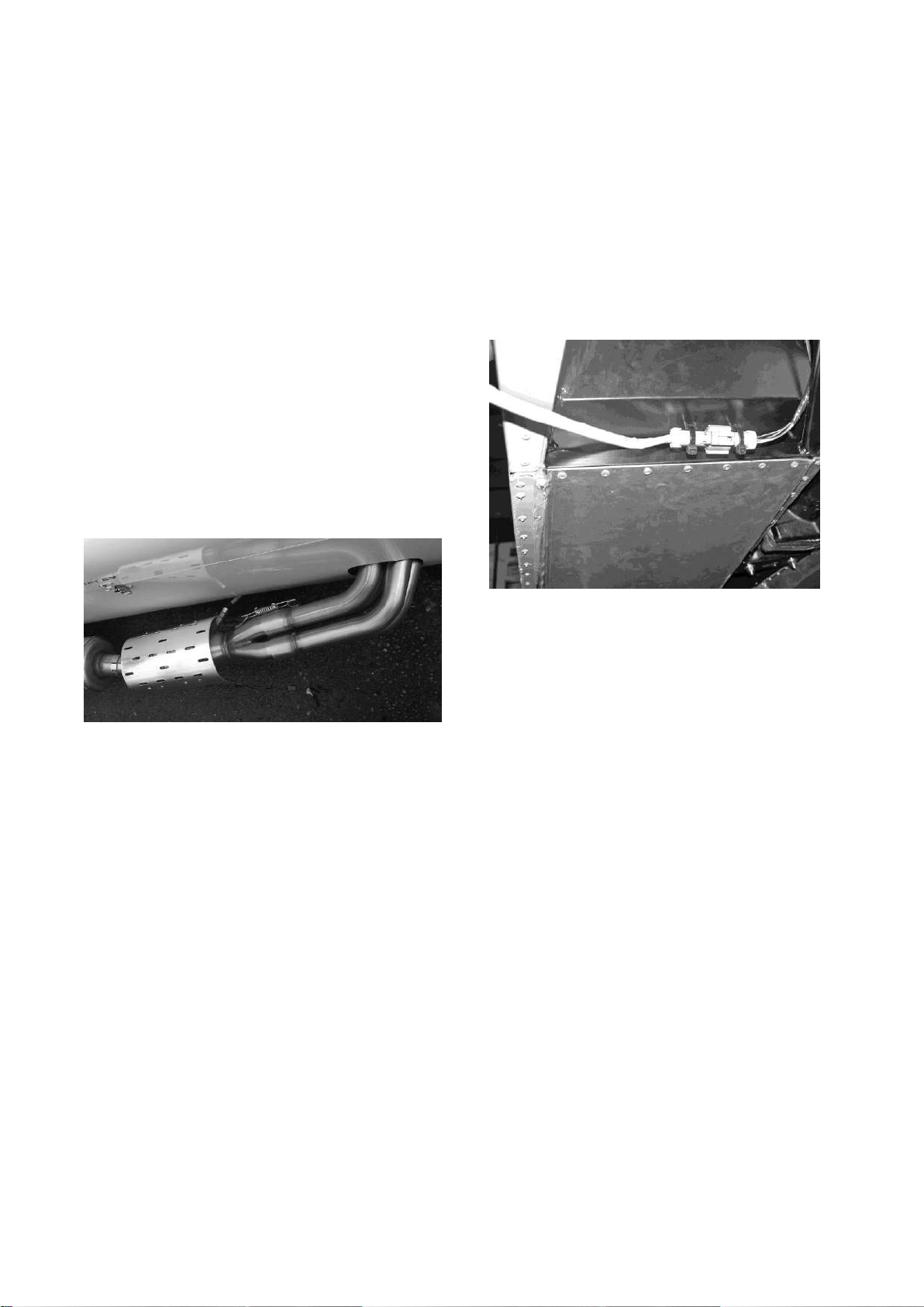
1. Primary pipe
2. Collector/catalyst (guard fitted)
Install the collector/catalyst over the
assembled primary pipes with the
threaded hole for the lambda probe faces
towards the side panel. Secure the
collector to the primary pipes with the two
springs, refer to Figure 49. Support the
weight of the collector such that the
primary pipes are not in contact with the
sides of the aperture and tighten the
primary pipe/cylinder head fasteners to 34
Nm.
Figure 44: Primary pipes and
collector/catalyst
NOTE
The lambda probe wiring passes under
the side of the car below the lower chassis
tube, it must not be routed through the
primary pipe aperture in the side panel.
Figure 45: Lambda probe connection
Fit the Lambda probe into the threaded
hole in the collector/catalyst and connect
the probe plug to the corresponding
socket from the engine wiring loom.
Secure the Lambda probe connection and
wiring to the chassis ensuring that it
cannot contact the hot exhaust or any
moving part, refer to Figure 50.
Undo the large worm drive clips and feed
them through the channels on the inside
of the collector/catalyst guard. Fit the
silencer guard to the silencer body with
the channels offset towards the rear of the
silencer and tighten the clips, refer to
Figure 51. Ensure that the clip drives are
not at the bottom of the silencer where
they could contact the road. Attach the
collector/catalyst guard in the same
manner.
NOTES
1. For a neater appearance position the
clips with the drive screw towards the
ground so that the clip ‘tail’ is out of sight
beneath the exhaust.
Page | 77
Page 79
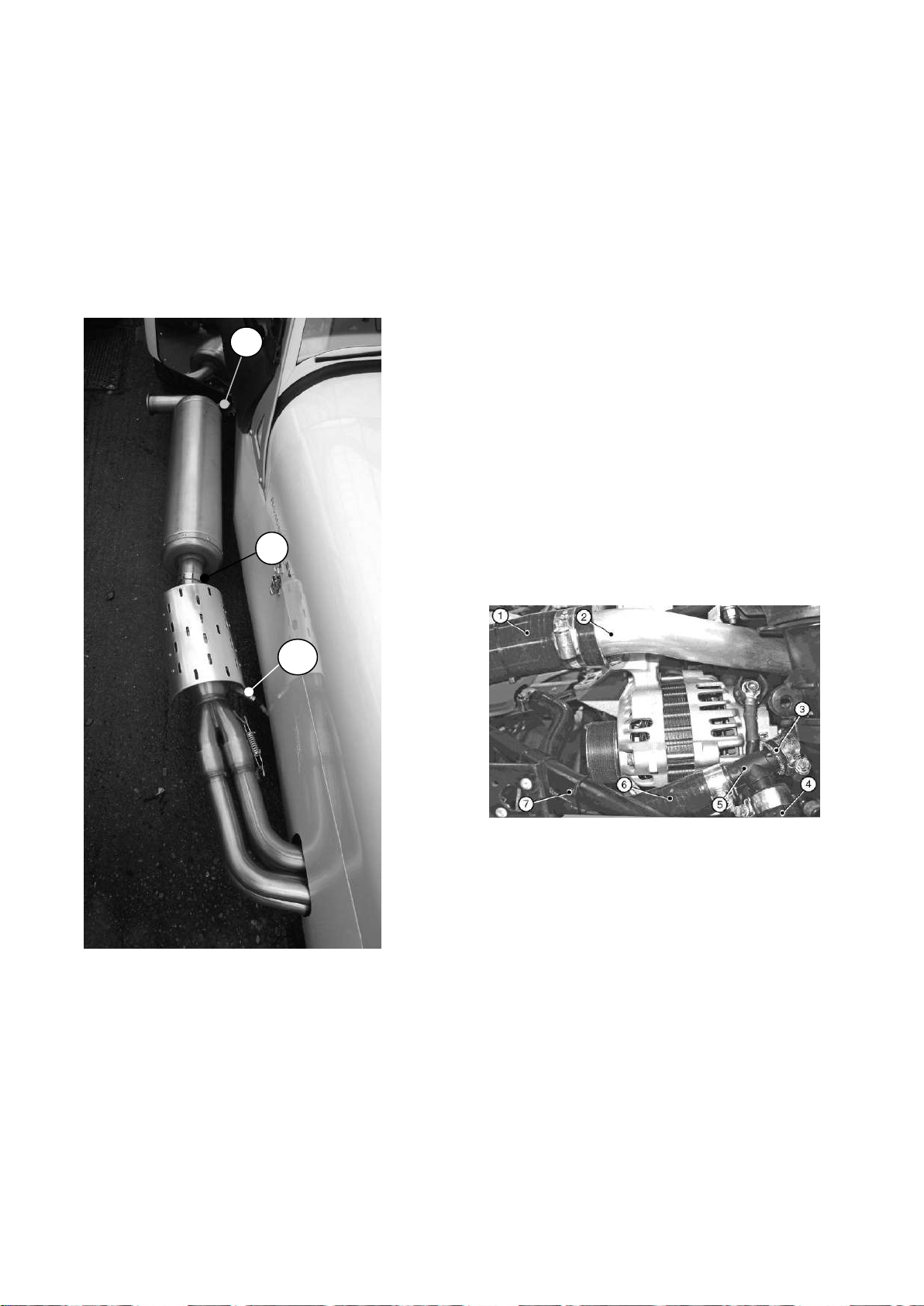
1. Silencer bracket
3. Lambda probe
2. Band clamp
1. Top radiator hose
5. ‘T’ piece
2. Water rail
6. Hose to expansion
tank
3. Hose to heater outlet
7. Cable tie
4. Hose to cylinder
block
1
3
2
Figure 46: Exhaust arrangement
2. To reduce the risk of damage it is
advisable to fit the silencer after the RH
rear wing has been attached.
outlet pipe. Locate the bracket at the rear
of the silence over the bobbin on the
silencer mounting bracket and secure with
a nut and spring washer. Tighten the nut
and band clamp. It may be necessary to
reposition the guards slightly.
7.1.7) Cooling system
Position a hose clip on the flexible top
radiator hose, apply rubber lubricant and
fit the hose to the end of the water rail
pipe emerging from the curve of the inlet
manifold, Refer to Fig 52. Do not tighten
the clip.
Figure 47: Coolant hoses
Loosely fit the single band clamp to the
front of the silencer and position the front
of the silencer over the collector/catalyst
Position a hose clip on the flexible bottom
radiator hose, apply rubber lubricant and
fit the hose to the larger of the two outlets
on the LH side of the engine block, Refer
Page | 78
Page 80
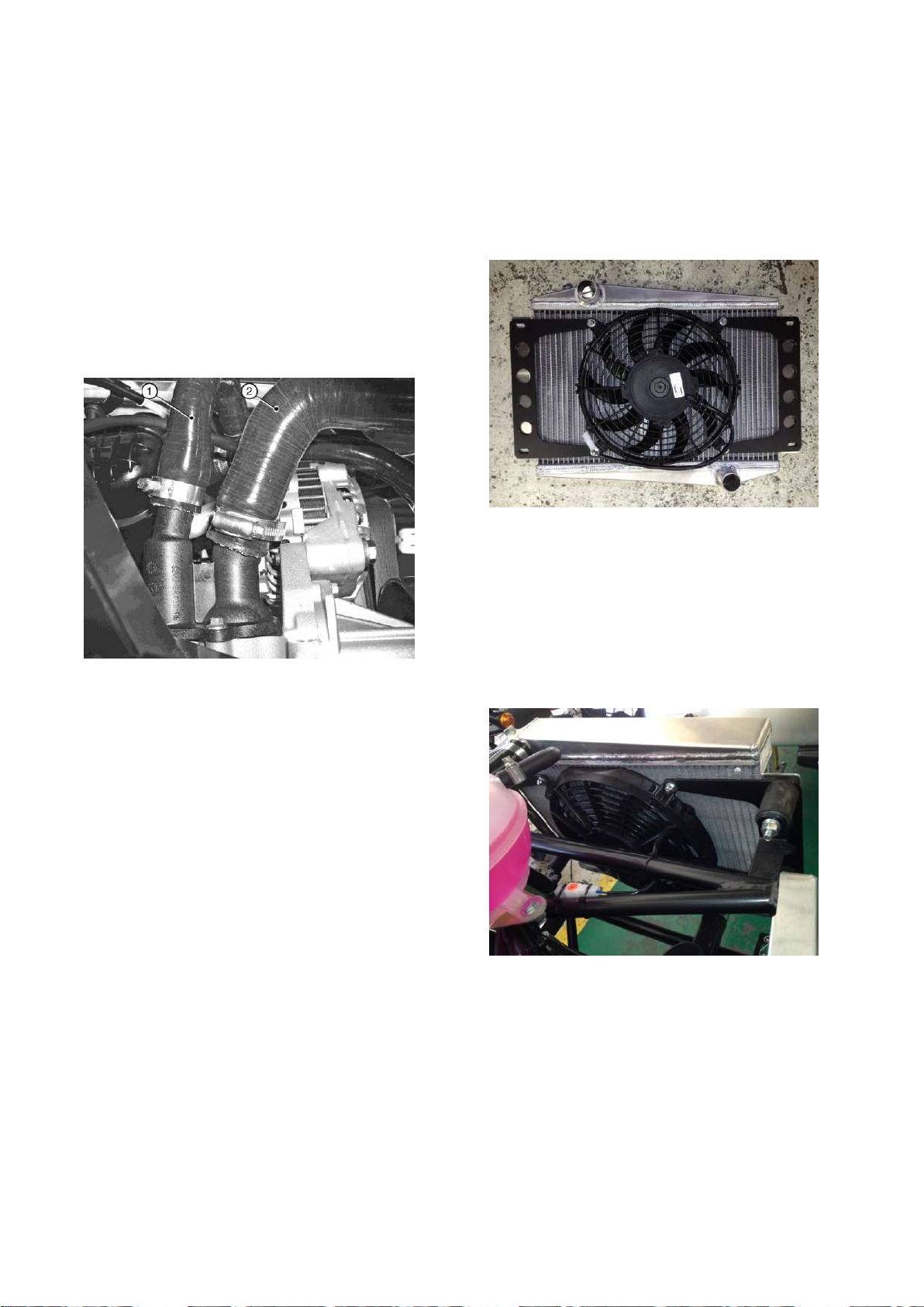
1. Hose to ‘T’ piece
2. Bottom radiator hose
1. Top hose connection
4. Fan power lead
2. Fan
5. Bottom hose connection
3. Fan legs
to Fig 53. The hose passes forwards
along the LH side of the engine bay
before turning to pass along the top of the
steering rack and turns again to meet the
radiator connection. Do not tighten the
clip.
Figure 48: Bottom hose engine
connection (viewed from bellow)
using four nuts and washer provided in
fastener pack (fastener pack 30C047A,
Item 7,10 & 13).
Figure 49: Radiator/fan prior to fitting
Fit the four rubber radiator mountings to
the front of the chassis and secure using
nuts, plain washer and spring
washers provided in the cooling pack.
Fit the four fan legs (polythene bag
marked 'cooling') to the cooling fan.
Secure the fan complete with legs to the
brackets,( using bolt 11 and nut 6 in pack
30C047A) the fan can then be mounted to
Figure 50: Standard radiator
arrangement
The radiator mounting arrangement on SV
models differs considerably from that
the bobbins, ensuring that the fan
electrical connector is located on the RH
side, mount the radiator to the bobbins
shown. SV kits include LH and RH
radiator mounting plates, refer to Figure
56; these plates must be fixed to the body
Page | 79
Page 81
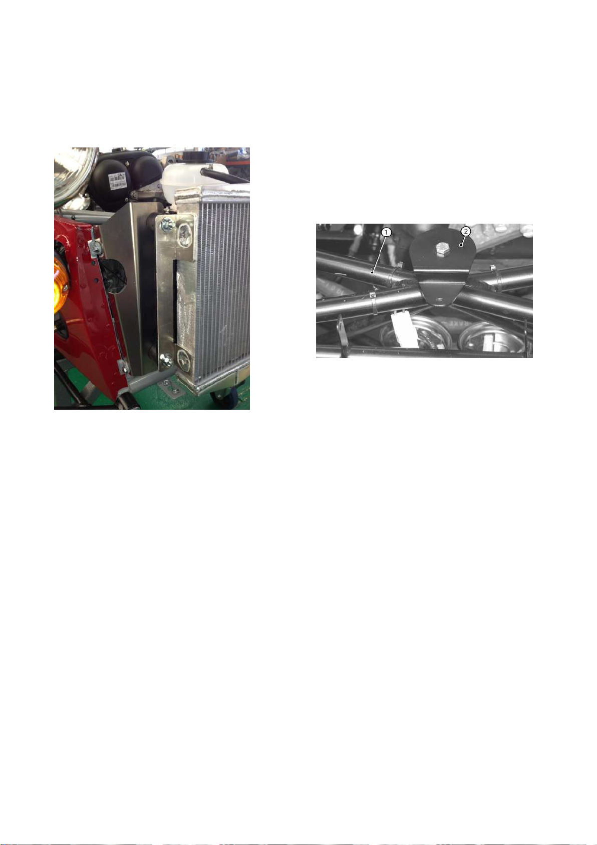
1. Cruciform
2. Expansion bottle mounting bracket
before attaching the rubber mountings
and the radiator.
Figure 51: SV radiator arrangement
Fit the expansion bottle mounting bracket
on the top of the cruciform, immediately
behind the radiator, refer to Fig 57, and
secure using bolt, plain washer and spring
washer. Tighten to 11 Nm.
Figure 52: Coolant expansion bottle
mounting bracket
Position hose clips on the forward ends of
the flexible top and bottom radiator hoses;
apply rubber lubricant and fit the hoses
over the connections on the radiator.
Tighten the clips at both ends of both
hoses.
NOTE
The flexible radiator hoses may need to
be trimmed to length.
Locate the two-pin plug containing the
black/green and black wires situated on
the upper front diagonal chassis member.
The round coolant expansion bottle sits on
the mounting bracket and is secured using
a setscrew, plain washer and nylocnut,
refer to Figure 66 for correct orientation of
the expansion tank hose connections.
7.1.7.1) Water bleed hoses
The smaller of the two inlets on the
coolant expansion bottle connects to the
rear RH side of the cylinder head, refer to
Figure 66
Connect the two-pin plug to the cooling
fan electrical connector. Secure the cable
to the chassis members using cable ties.
Route the 5/16” bore hose, along the top
radiator hose and fuel rail and around the
Page | 80
Page 82
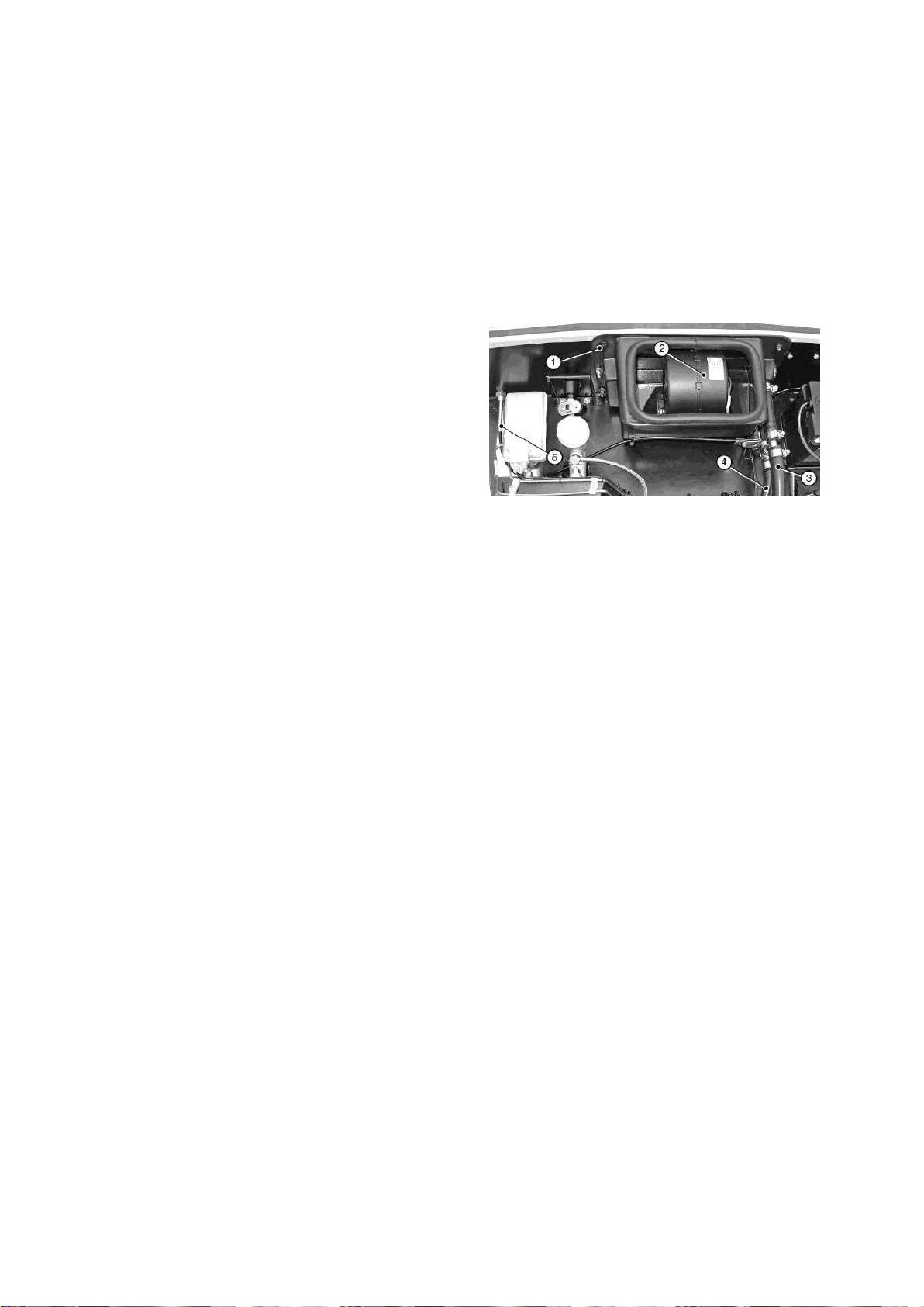
1. Washer plate
4. Heater inlet hose
2. Heater
5. Heater control
cable
3. Heater outlet hose
back of the cylinder head. Secure using
hose clips (10).
7.1.7.2) Heater and associated hoses
Remove and retain the four screws, nyloc
nuts and washers and the two washer
plates securing the diffuser panel to the
heater. Position the diffuser panel on the
inside surface of the scuttle with the air
vents facing down and insert the four
screws from the inside. Pass the heater
harness through the large hole in the
scuttle panel and locate the heater over
the screws, secure with the washer plates,
nyloc nuts, washers and two additional
temp sender submarine and remember to
bolt the earth tag on first.
Figure 53: Heater installation
screws from the fastener pack, refer to Fig
58. Connect the heater harness connector
heater to the matching plug, located under
the dashboard.
NOTE
Cars not fitted with a heater will be
supplied with a blanking plate. Apply a
small amount of silicon sealant around the
edge of the plate to seal it.
Academy Cars.
From the T piece on the LH side of the
block route the hose to the front of the
Modine which is near the oil filter. From
the rear of the Modine route the J hose up
to the rear RH side of the engine. In this
Heater hose is supplied as three pre-
formed pieces; a short ‘L’ shape, a long ‘L’
shape and a long ‘J’ shape:
The short ‘L’ connects the ‘T’ piece to the
engine inlet next to the bottom radiator
hose.
The long ‘L’ shape must be cut in two to
provide a long straight hose (to connect
the ‘T’ piece to the heater outlet) and a
short ‘L’ shape (to connect the expansion
tank to the ‘T’ piece). Measure the
relevant distances carefully before cutting
the hose.
pipe under the coil pack you need to fit the
Before fitting any hoses remove the bungs
from the ends of the heater pipes.
Page | 81
Page 83

The long ‘J’ hose connects the heater inlet
to the water outlet at the rear of the
cylinder head (next to the top hose ‘U’
bend). This hose must be trimmed to
length. Cut a 240 mm length of hose from
the straight leg and cut this into two 120
mm pieces. Use the 120 mm pieces to
connect the heater inlet and outlet to the
heater valve.
The larger of the two inlets on the coolant
expansion bottle must connect to one end
of the cross-bar of the large ‘T’ piece
(near the alternator) that also connects to
the heater valve (outlet side) and to the
refer to Fig 59. Connect the other side of
the heater valve upper (outlet) connection
to the straight connector at the top of the
heater. Apply rubber lubricant where
necessary and secure using hose clips.
Ensure that the hose is routed to avoid
chafing, use cable ties as necessary.
Trim to length and connect the long ‘J’
hose between the lower (inlet) connection
of the heater valve and the outlet at the
back of the cylinder head (next to the top
‘U’ hose). Connect the curved pipe on the
heater valve to the lower (inlet) connection
on the heater using a short length of 5/8”
smaller of the two connections at the front
LH side of the engine block, refer to Fig
52. Measure and cut the long, 5/8” bore,
‘L’ shaped hose as described previously.
Apply rubber lubricant to the hose and fit
to the coolant expansion bottle and ‘T’
piece securing with a hose clip at each
end.
Apply rubber lubricant and connect the
short ‘L’ shaped hose to the smaller of the
two connections at the LH front of the
engine block, connect this hose to the
stem of the large ‘T’ piece. Secure using
hose clips.
bore hose, refer to Fig 59. Apply rubber
lubricant where necessary and secure
using hose clips. Ensure that the hose is
routed to avoid chafing, use cable ties as
necessary. Do not fully tighten the hose
clips at the heater end at this point.
NOTE
On cars where no heater is fitted the
relevant connections at the rear of the
cylinder head and on the front LH side of
the engine block must be joined by a
suitable length of hose.
Use the cut length of 5/8” bore hose (from
the long ‘L’ hose) to connect the
remaining leg of the ‘T’ piece to the upper
(outlet) connection on the heater valve,
Page | 82
Page 84
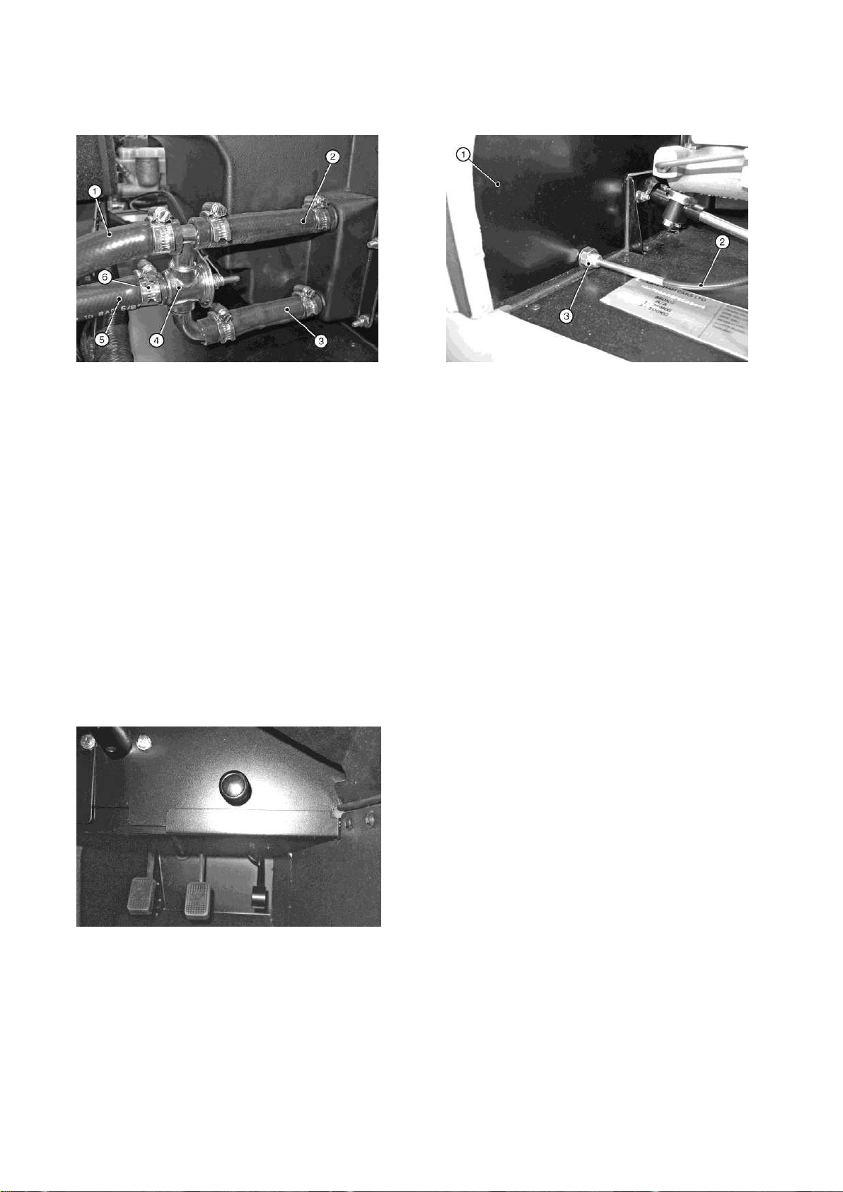
1. Hose to large ‘T’
4. Heater valve
2. Heater outlet
5. Hose to cylinder head
3. Heater inlet
6.Hose clip(s)
1. Scuttle panel
2. Heater control cable
3. Locknut
Figure 54: Heater valve arrangement
Remove and retain the locknut and
Figure 56: Heater control cable
Connect the other end to the heater
washer from the heater control cable and
pass it from inside the cockpit, through the
hole in the front face of the scuttle, refer to
Figs 60 and 61. Secure the cable in place
using the locknut and washer provided.
Figure 55: Heater control location
control valve by sliding the eyelet on the
inner cable over the peg on the heater
valve operating arm then slide the outer
cable under the adjacent clamp and
tighten the screw to secure in place, refer
to Figure 62. Ensure that the valve travels
through its full range when operated from
inside the car. This can be adjusted by
slackening the clamp that locates the
outer cable to the valve and sliding the
cable one way or another.
Page | 83
Page 85
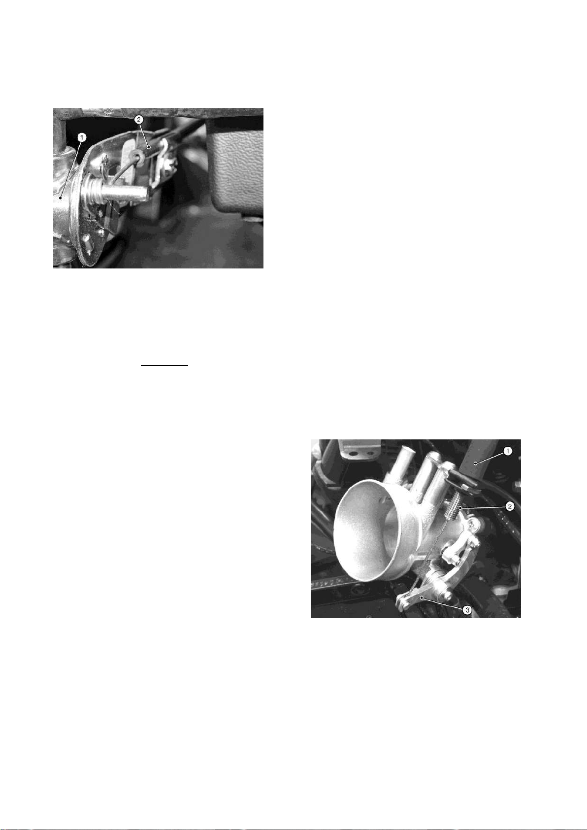
1. Heater valve
2. Heater control cable
1. Throttle cable
2. Throttle cable adjuster
3. Throttle body linkage
Figure 57: Heater control cable
attachment
Warning
inlet hose with coolant solution. When the
hose is full refit it to the heater inlet and
secure with the hose clip. This procedure
should minimise the amount of bleeding
required once the engine is running for the
first time.
7.1.8) Throttle cable fitment
Attach the throttle cable to the linkage on
the throttle body by engaging the nipple in
the throttle operating lever and then
clipping its square shaped black plastic
adjuster onto the adjacent bracket. This
adjuster can be threaded up and down the
cable outer to adjust the throttle pedal
Due consideration should be given to
the highly flammable nature of
petroleum or alcohol based products
and their vapours. Serious burns can
result from incorrect use.
Fill the cooling system with a 50%
antifreeze solution (refer to Owner's
Handbook for Caterham recommended
coolant). Add the coolant solution to the
expansion bottle. Place paper or cloth on
the scuttle in the area below the heater
inlet/outlet hoses. Ensure that the heater
valve is in the fully open position (control
knob pulled towards the driver) and
position, refer to Figure 63.
Figure 58: Throttle cable to throttle
body
remove the heater inlet (top connector)
hose which was previously left loose.
Temporarily seal off the heater valve inlet
and at the same time back fill the heater
Page | 84
Page 86
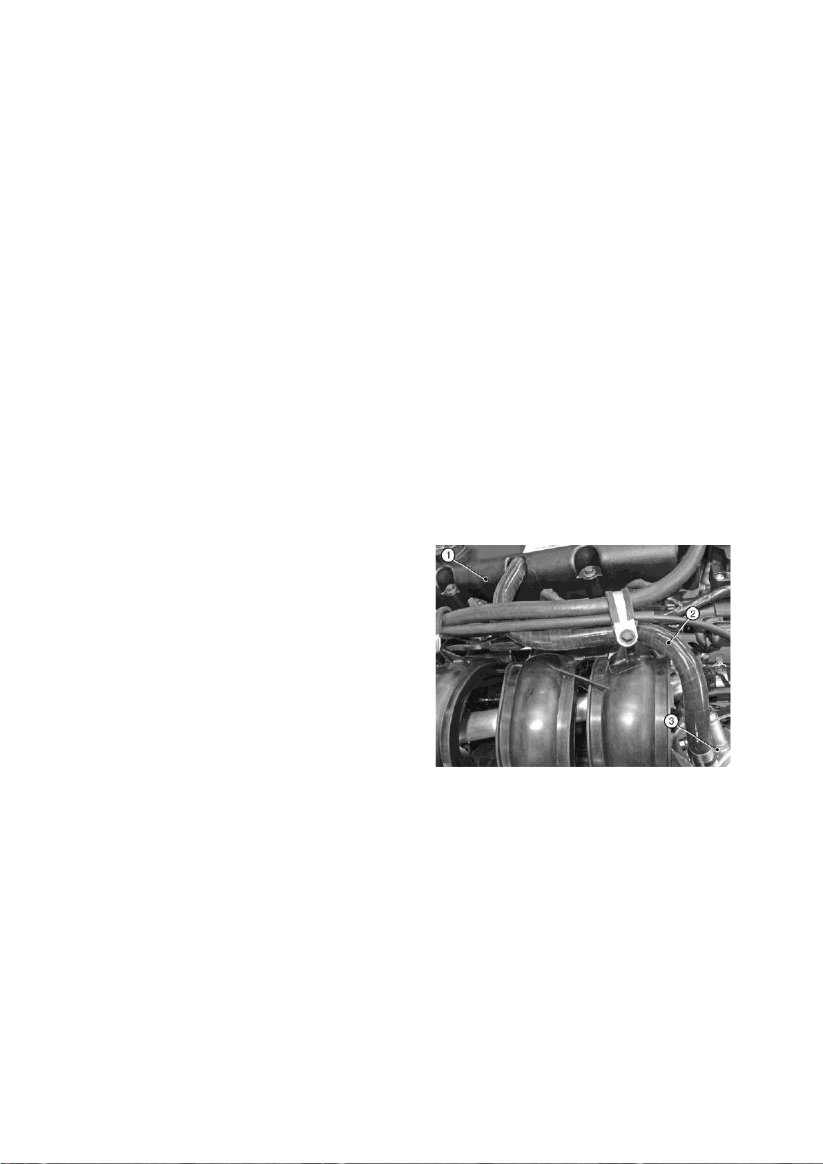
1. Cam cover
2. Breather pipe
3. Throttle body
Route the other end of the cable around
the front of the cam cover; refer to Fig 64
and through the 22 mm hole in the front of
the pedal box and clip the plastic seat into
place. The inner cable is fed into the slot
on the top of the pedal with the portion of
cable protruding past the cable
termination located through the hole. The
top of the pedal should be gently
squeezed with a pair of pliers to capture
the cable and prevent it escaping.
NOTE
In order to obtain a preferred pedal height
and achieve adequate cable tension it
may be necessary to bend the top of the
Ensure that the pipe is routed to avoid
chafing, use cable ties as necessary.
On Sigma 140 the throttle body is blocked
off and the breather from the cam cover
goes to a bottle located at the front LH
side of the chassis above the steering
rack, there is also another breather pipe
that is already fitted just below the inlet
manifold that also goes to the breather
bottle.
The academy is similar to the 140 except
the breather bottle is mounted on the front
of the scuttle.
Figure 59: Breather pipe
pedal prior to locating the cable. This is
done by inserting a Phillips screwdriver
into the top of the pedal, bracing the
bottom of the pedal with a block of wood,
and gently bending the top of the pedal so
as to take up the slack in the cable. Use
the adjusting mechanism at the throttle
body end of the cable to remove any free
play. Once pedal has been manipulated
to desired position; ensure that no part
of the pedal is in contact with the head
of the securing bolt.
7.1.9) Breather pipe fitment
Fit the breather pipe between the throttle
body and engine cam cover, refer to Fig
64. Apply rubber lubricant where
necessary and secure using hose clips.
Page | 85
Page 87
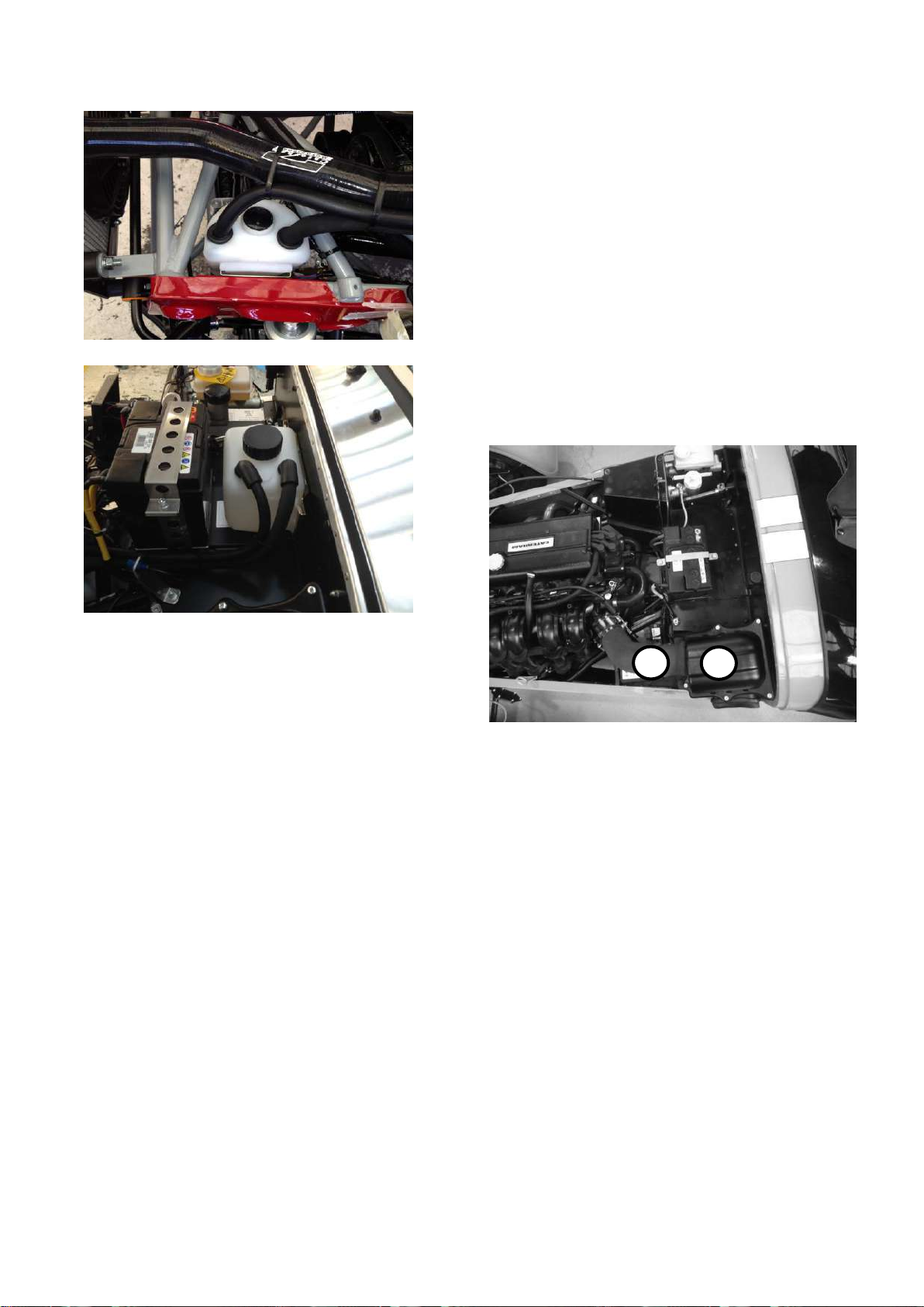
1. Air intake
2. Trunking
1
2
Check that the throttle operates smoothly
without sticking.
7.1.11) Seven 270 and Academy – air
intake
Fit the airbox and trunking as shown
below. The airbox is mounted on three
rubber bobbins secured to the heater tray
panel.
Figure 60: Air intake and trunking
7.1.10) Air filter fitment
Fit the Caterham air filter element to the
throttle body housing and secure using
the hose clip provided. The hose clip
should not be over tightened as it is
possible to distort the throttle body and
prevent smooth operation of the throttle.
Page | 86
Page 88
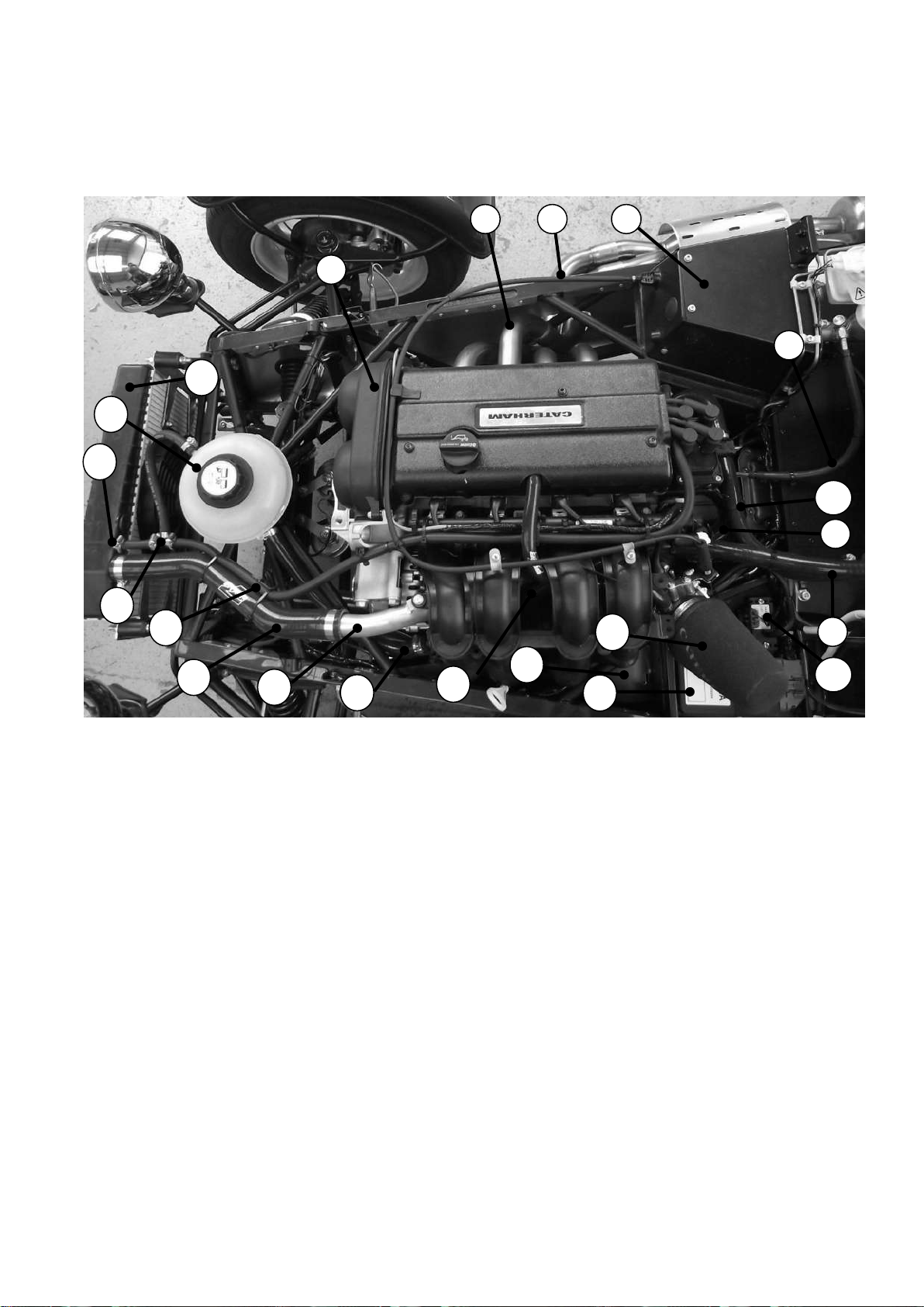
1. Engine
8. Heater outlet
15. Water rail
2. Exhaust
9. MAP unit
16. Top radiator hose
3. Throttle cable
10. ECU
17. Water bleed hose
4. Pedal box
11. Air filter
18. Small ‘T’ piece
5. Clutch hose
12. Heater outlet
19. Blanking plug
6. Heater inlet hose
13. Heater outlet hose
20. Expansion bottle
7. ‘U’ hose
14. Large ‘T’ piece
21. Radiator
1
2 3 4
5
6
7
8
9
10
11
21
20
19
18
17
16
15
14
13
12
Figure 61: Sigma 125 engine bay overview
Page | 87
Page 89
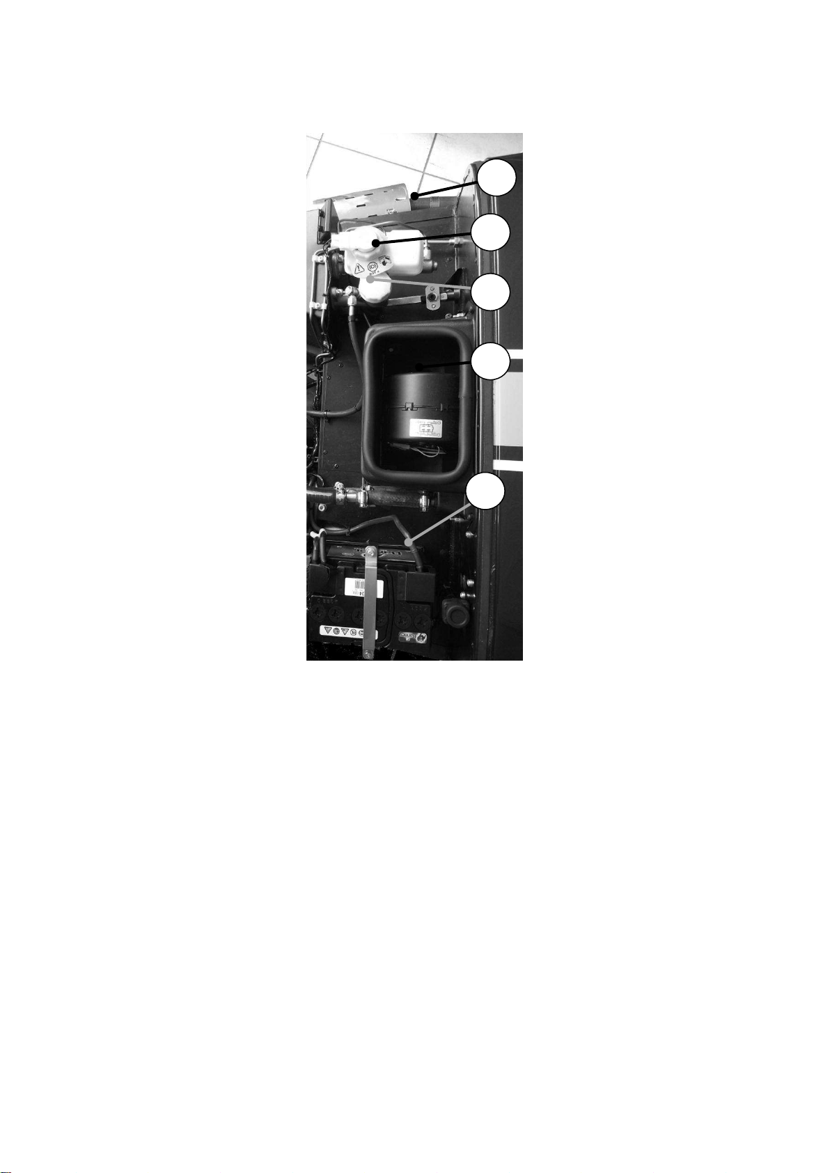
1. Brake master cylinder
4. Heater control cable
2. Clutch master cylinder
5. Battery
3. Heater
1
2 4 3
5
Figure 62: Sigma 125 engine bay overview (rear)
Page | 88
Page 90

7.2) Duratec Engine – Seven 360 (exc
Item
Description
Engine hoist and sling
SWL if 150 Kg (min)
dry sump option – see Seven 420)
7.2.1) Preparation
The special tools detailed in Table 17 will
be required.
washer bottle. Trim the tube to length and
attach to the washer motor.
Connect the washer motor to the wiring
loom via the two pin plug adjacent to the
washer bottle mounting. To ease fitment
Table 17: Special tools required for the
Seven 360 engine
7.2.1.1) Screen wash/wipe
NOTE
The bracket for the washer bottle must be
fixed to the front of the passenger side
foot box before the engine is installed.
Remove the securing nut from the base of
the washer jet and pass the washer jet
through the hole in the centre of the
scuttle and secure with the plastic
securing nut. Fit the clear plastic tubing to
the washer jet. Dip the end of the clear
plastic tubing in hot water to soften in
order to make fitting easier.
Route the clear washer tubing along the
wiring loom behind the dashboard and
attach using cable ties, to prevent it falling
down into view. Pass it down through the
large grommet in the top of the
transmission tunnel and along the engine
bay diagonal tube until in line with the
of the two pin plug the washer motor can
be removed from the washer bottle, the
two pin plug fitted and the washer motor
reinserted into the washer bottle.
The windscreen wipers must not be
fitted until the wiper motor has been
run and allowed to park in order to
prevent damage to the paintwork. Fit
the wiper arms so that they are horizontal
when parked. The wiper arms must move
smoothly through their range of travel.
NOTE
A small amount of water splashed on the
windscreen will prevent the wiper blades
from juddering during test and adjustment.
7.2.1.2) Engine preparation
The large diameter short 'L' shape hose
should be fitted onto the aluminium water
outlet located on the rear of the cylinder
head, refer to Fig 68. Apply rubber
lubricant to the long end of the hose and
push over the outlet; rotate the hose until
the short end sits along the LH side of the
engine refer fig 68. Secure using a hose
clip.
Page | 89
Page 91
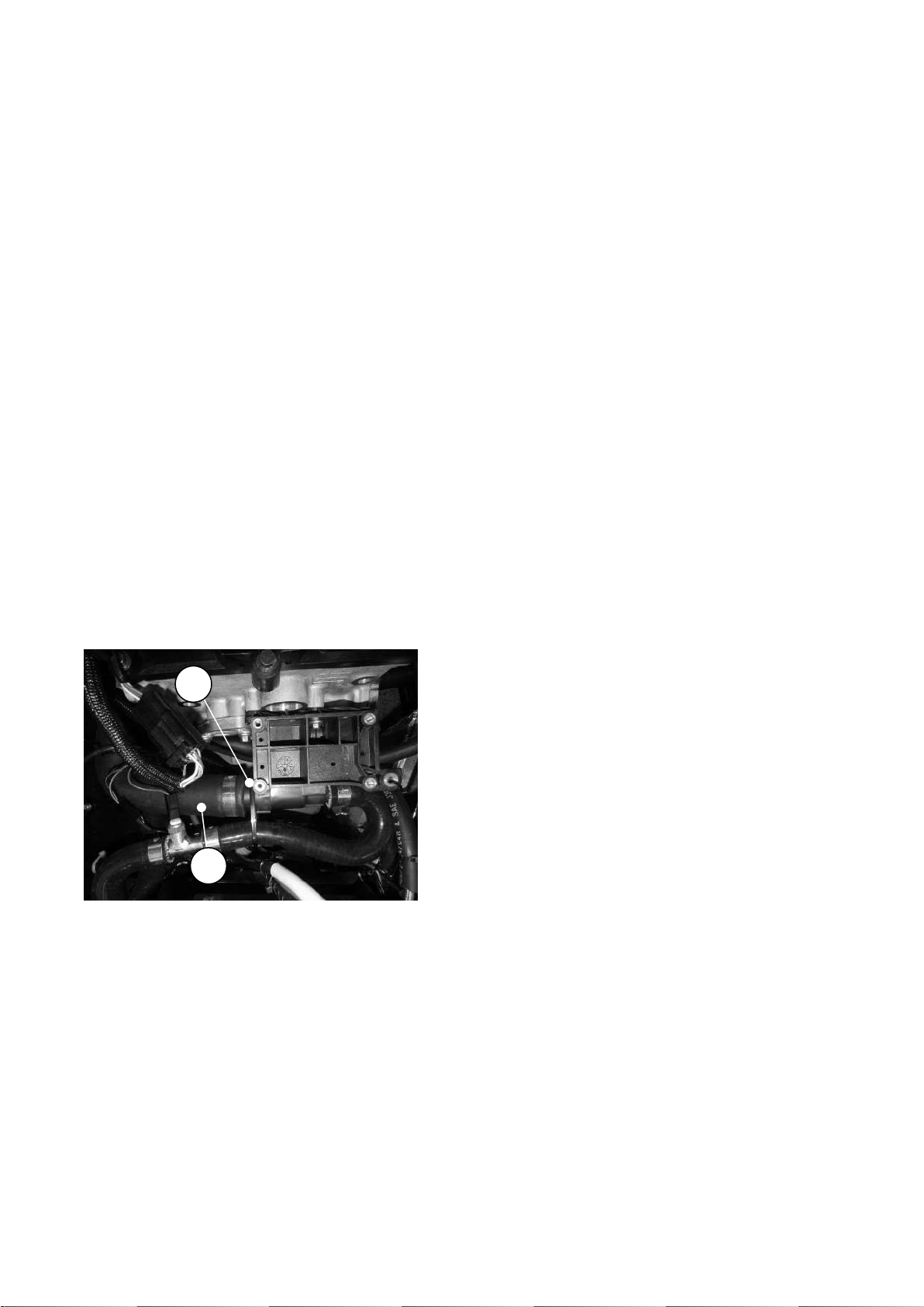
1. Engine connection
2. Long ‘L’ hose
2
1
Apply rubber lubricant to the end of the
water rail; pass the rail from the front of
the engine, over the alternator, and under
the curve of the plenum chamber. Insert
the pipe into the short end of the ‘L’ shape
hose and secure using a hose clip. Align
the water rail mountings with the lugs
under the Plenum chamber and secure
using screws, nuts and washers provided.
NOTE
Water rail might have already been fitted
to the engine.
7.2.1.3) Chassis preparation
Protect the appearance of the engine bay
chassis tubes and pedal box sides and
edges by covering with card and/or
masking tape.
Ensure that all wires and connector plugs
are secured and will not snag or catch the
engine/gearbox as it is lowered.
NOTE
Before fitting engine mounting rubber
blocks ensure that the large threaded
(1/2" UNF) boss in the centre is clear of
rubber and that the bolt will thread in
Figure 63: Water outlet and 'L' shape
hose
Remove and retain the gearbox filler plug.
Remove the plastic plug from the gearbox
tailshaft housing. Removal of these plugs
is not essential; however access is
restricted within the confines of the
transmission tunnel.
cleanly.
Fit the engine mounting rubber block to
the RH side of the engine bay. The two
bolts (fastener pack 30P012A Item 3),
plain washer (12) are passed downwards
through the mounting, through the chassis
and are secured with nyloc nuts (9) and
plain washers (12). Do not tighten.
Fit the engine mounting rubber block to
the LH side of the engine bay, locate the
engine earth lead (a black lead
approximately 300 mm long), pass bolt (2)
and washer (12) downwards through the
lead, through the front hole of the engine
mounting block, through the chassis and
secure with nyloc nut (9) and plain washer
(12). Remove a little paint from the
chassis/mounting to ensure that a good
Page | 90
Page 92
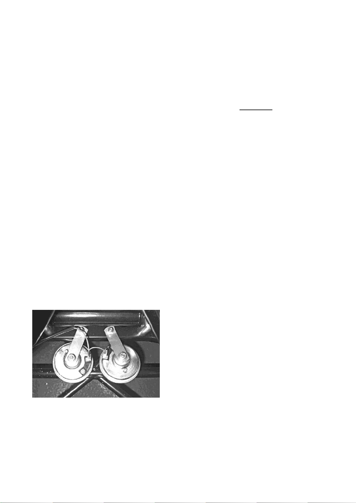
electrical contact is made. Pass bolt (3),
plain washer (12) downwards through the
rear hole of the engine mounting block,
through the chassis and secure with
nyloc (9) and plain washer (12). Do not
tighten.
Locate the twin electric horns on the two
studs near the rear edge of the steering
rack platform. Before fitting the horns,
loosen the 13 mm nut in the centre of
each horn, this will allow rotation of the
horns so that the electrical connections
are closer together.
Secure the horns with the nyloc nuts
provided and ensure that it is not possible
for the horns to come into contact with
each other, the steering rack or other
components in the engine bay refer to
Figure 69.
Figure 64: Horn location
above the horns on the front upper cross
member.
7.2.2) Installation of engine/gearbox into
chassis
Warnings
1. Never work underneath a car without
supporting it on axle stands or
equivalent. Do not rely on a jack alone.
2. Use appropriate eye protection
whilst working under the car.
3. For Duratec engines, Alternator and
starter motor must be removed before
engine installation.
Using the lifting hoist and sling detailed in
Table 17, attach the engine/gearbox using
the lifting eyes provided on the engine,
lower the engine/gearbox assembly into
the engine bay at an angle of between 30-
40 (with the engine higher than the
Tighten the 13 mm nut in the centre of
each horn and connect the horns to the
electrical harness by the purple and
yellow wires and connectors located
gearbox). Insert the gearbox assembly
into the transmission tunnel.
Continue to slide the engine/gearbox
rearward until the holes in the gearbox
mounting line up with the holes in the
chassis cross member. If the differential
and Propshaft have already been fitted,
ensure that the Propshaft locates into the
gearbox tailshaft housing.
Attach the LH engine mounting using the
two M8 x 25 mm bolts (fastener pack
Page | 91
Page 93

36G006A Item 4) and one M8 x 30 mm
bolt (5), do not fully tighten the bolts.
Attach the RH engine mounting using the
two M8 x 35 mm bolts (6) and one M10 x
40 mm bolt (2). Do not finally tighten the
engine mounting retaining bolts until
advised later in this section.
For cars equipped with a 5-speed
gearbox, the gearbox mount should now
be fitted.
chassis, tighten to 20Nm, bolts can be
found in pack 3EZ1105
At the engine mountings, pass the bolts
(fastener pack 30P012A Item 1) down
through the tube on the outer end of the
engine mounting brackets. Screw the
bolts loosely into the threaded bush in the
centre of the rubber engine mounting. It is
recommended that the engine is not
removed from the hoist until all the bolts
have been tightened (detailed later in this
section).
Adjust the gearbox on its slotted
mountings to achieve equal clearance
Lower the engine onto the rubber engine
mountings. Using 2 M14x40 bolts with a
plain washer and thread lock bolt the
mount to the gearbox, with the cut out
facing the front, tighten to 40Nm,
within the transmission tunnel. This must
be checked carefully as clearances are
tight and poor alignment can cause the
gearbox to contact the chassis under
cornering.
Bolt the gearbox mounting rubber to the
chassis using bolts (fastener pack
30P012A Item 4) passed down through
the outer metal part of the rubber
mounting and then through the elongated
holes in the chassis. Secure with a plain
washer (12) and nyloc nut (9) on each bolt
and tighten to 20 Nm.
Finally tighten the fixings detailed in
Table 18.
Using 4 M8x40 caphead bolts with a plain
washers and nyloc bolt the mount to the
Page | 92
Page 94

Fixing
Torque
Engine mounting to block
34Nm
Engine mounting to mounting
rubbers
41Nm
Engine mounting rubbers to
chassis
20Nm
Gearbox mounting rubber to
chassis
20Nm
Table 18: Gearbox torque figures for
Seven 360 engine
NOTES
1. It is now safe to remove the engine
hoist.
2.Wiring – Every effort is made to clearly
explain and identify all the electrical
connections as you go through this
section; however the loom fitted to your
car may have additional wires and
connectors that are not required on your
vehicle. To help clarify this, a wiring
diagram can be found in the electrical
system.
7.2.3) Electrical connections
The engine wiring loom is already
attached to the engine and some
ancillaries, however it is necessary to link
the engine wiring loom to the remaining
ancillaries and the vehicle wiring loom. All
the plastic connecting plugs are matched
pairs so it is not possible to connect them
Fit the gear lever to the top of gearbox
tailshaft housing and secure with three
setscrews (7). No washers are required;
tighten to a torque of 20 Nm.
Fit the reverse light switch (polythene bag)
into the side of the gearbox. This can be
accessed via the hole in the RH side of
the transmission tunnel. The switch
should be inserted finger tight and then
tightened a further quarter of a turn using
a suitable sized spanner. Connect the
wiring loom to the reverse light switch.
From the cockpit, insert the large grommet
(polythene bag) to cover the access hole
incorrectly.
Attach the grey, multi-pin plug to the
respective socket on the Engine Control
Unit (ECU), which is located on the
passenger side heater tray, forward of the
battery. Make the connection and ensure
that the red retaining clip is pushed fully
home, refer to Figure70.
in the transmission tunnel.
Page | 93
Page 95
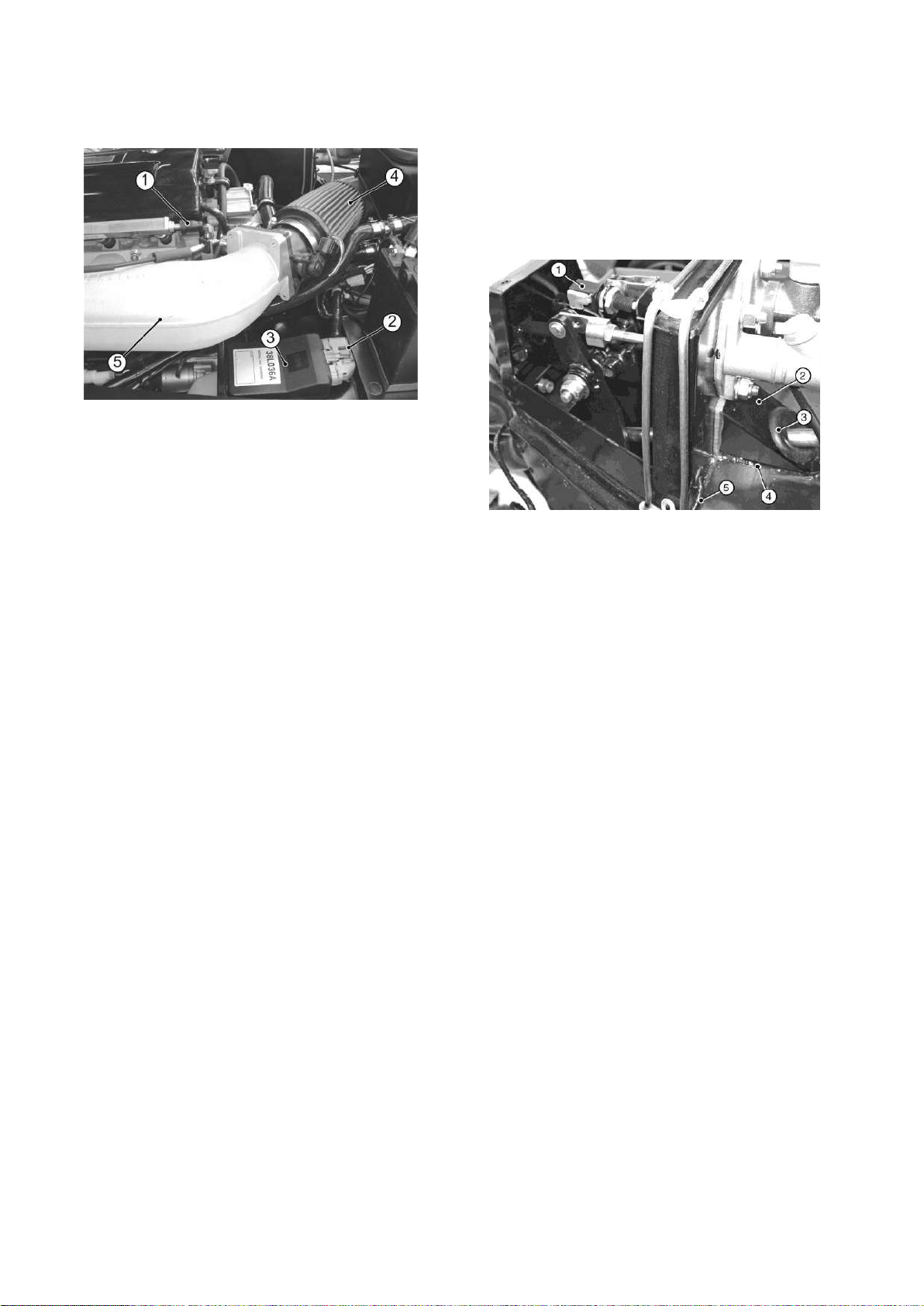
1. Fuel pipe
connection
3. ECU
4. Air filter
2. Multi-pin plug
5. Plenum chamber
1. Brake light switch
4. Sealant
2. Cheese wedge
5. Brake light switch
harness
3. Grommet
Figure 65: ECU
important). Fit the grommet into the hole
and ensure that the harness will not foul
the steering column or pedals.
Figure 66: Brake light switch harness
Connect the white/red/black wire plug
from the oil pressure sender on the LH
side of the engine block to the plug on the
engine loom and route with cable ties
(Might have already been connected).
The black wire with ring terminals in the
engine loom is earth connections. Attach
to a suitable earth point on the bulkhead.
The green, green/purple pair (with
grommet) in the engine loom is for the
brake light switch. The brake light switch
is inside the drivers pedal box and the
harness may be connected during
installation of the steering column. Pass
The longest wire from the engine loom
(terminating in a 4-pin plug) is the
connection for the exhaust mounted
lambda probe. This cannot be connected
until the exhaust primary pipes and
collector/catalyst is fitted, refer to cooling
systems (section 7.1.7).
Remove the outermost Bell housing
securing bolt and spring washer. Pass
the Bell housing mounting bolt and
attached spring washer through the black
the brake light switch harness through the
hole in the rear of the pedal box, refer to
Fig 71 and push the two female
connectors onto the male connectors of
the brake light switch (orientation is not
battery earth lead and secure to the Bell-
housing. Tighten to 34 Nm.
Connect the red lead from the starter
motor to the battery.
Page | 94
Page 96
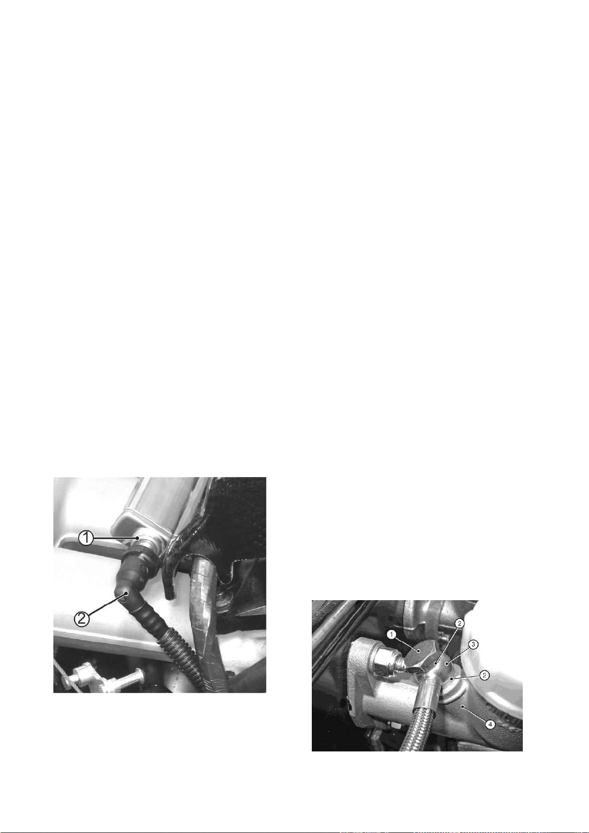
1. Fuel rail connection
2. Fuel pipe (from pump)
NOTE
In case of battery master switch, connect
red leads from master switch to battery
and starter motor as marked.
Connect the brown lead from the
alternator to the starter.
Connect the brown/red wire from the
chassis loom to the starter solenoid.
7.2.4) Fuel systems
The black, corrugated plastic, high
pressure fuel pipe from the fuel pump
emerges from the transmission tunnel and
is a push-fit on the connection at the rear
of the fuel rail, refer to Fig 72. Note that
there is no fuel return pipe with this
system.
Once fitted the pipe cannot be removed
without a special tool. Ensure that the pipe
is kink free and routed away from possible
snags or chafe points. Push the
connection on the pipe firmly onto the
elbow and check that it is securely
attached. Secure the pipe with cable ties if
necessary.
7.2.5) Clutch hydraulic hose
The clutch hydraulic hose is already
connected to the clutch mechanism. Fit a
copper washer to the banjo bolt and pass
the banjo bolt through the union at the end
of the hose, refer to Figure 73 (banjo bolt
and the washers can be found in a bag
attached to clutch hose) . Fit the second
copper washer to the banjo bolt and screw
the banjo bolt into the clutch master
Figure 67: Fuel pipe connection
cylinder outlet port (remove the port plug).
Do not fully tighten the banjo bolt.
Figure 68: Clutch master cylinder hose
union
Page | 95
Page 97
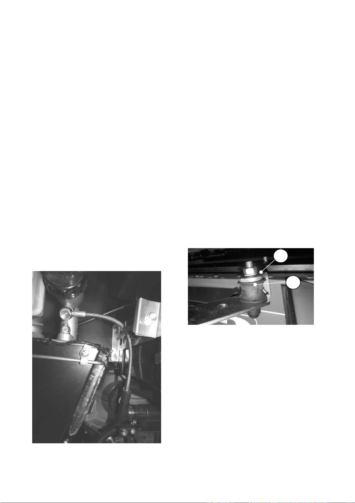
1. Banjo bolt
3. Hose union
2. Copper washers
4. Clutch master
cylinder
1. Angle bracket
2. Bobbin
1
2
7.2.6) Exhaust system
The standard exhaust system consists of
Route the hose down the side of the pedal
box, over the wiring loom (under the
heater hose if fitted) and across the top of
the bell-housing, Refer to Figure 74.
Secure the hose with cable ties if
necessary, to prevent chafing and tighten
the banjo bolt (the clutch system is filled
and bled during start-up/final checks.
four primary pipes, a collector assembly
which also incorporates the catalytic
converter and a one piece silencer and tail
pipe.
Bolt the exhaust mounting bracket
(polythene bag marked 'exhaust') to the
RH side of the car forward of the rear
wheel, using setscrew (fastener pack
30X020A Item 1) and spring washers (3),
refer to Fig 75. Secure the bobbin to the
angle bracket with a nut (2) and spring
washer (3).
Figure 70: Exhaust mounting
Figure 69: Clutch hydraulic hose
Remove the exhaust gasket and
associated fasteners from the RH side of
the cylinder head, remove any masking
tape protecting the exhaust ports and
clean off any adhesive residue.
The exhaust primary pipes are marked
with their part numbers.
Page | 96
Page 98

Series 3.
CSP903 is for # 1 (front) cylinder
CSP904 is for # 2 cylinder.
CSP905 is for # 3 cylinder.
CSP906 is for # 4 (rear) cylinder.
Protect the area around the square
aperture in the side panel with masking
tape and card, place the exhaust gasket
over the remaining studs and fit the
primary pipes in the following sequence:
1. Pass the flanged end of # 4 pipe
inwards, attach the flange loosely to the
For SV use the same procedure to fit the
primary, the sequence to fit the primary is
4,3,2,1.
58X0011A is for #1(front) cylinder.
58X0012A is for #2 cylinder.
58X0013A is for #3 cylinder
58X0014A is for #4 (rear) cylinder
When the primary pipes are in place, fit
the remaining fasteners but do not tighten
them.
Install the collector/catalyst over the
assembled primary pipes with the
cylinder head and ensure that the pipe sits
in the top LH corner of the aperture
(viewed from outside).
2. Pass the flanged end of # 3 pipe
inwards, attach the flange loosely to the
cylinder head and ensure that the pipe sits
in the bottom LH corner of the aperture.
3. Pass the plain end of # 2 pipe
outwards, attach the flange loosely to the
cylinder head and ensure that the pipe sits
in the bottom RH corner of the aperture.
4. Pass the plain end of # 1 pipe
outwards, attach the flange loosely to the
threaded hole for the lambda probe faces
towards the side panel. Secure the
collector to the primary pipes with the two
springs, refer to Fig 76. Support the
weight of the collector such that the
primary pipes are not in contact with the
sides of the aperture and tighten the
primary pipe/cylinder head fasteners to 34
Nm.
cylinder head and ensure that the pipe sits
in the top RH corner of the aperture.
NOTE
Page | 97
Page 99
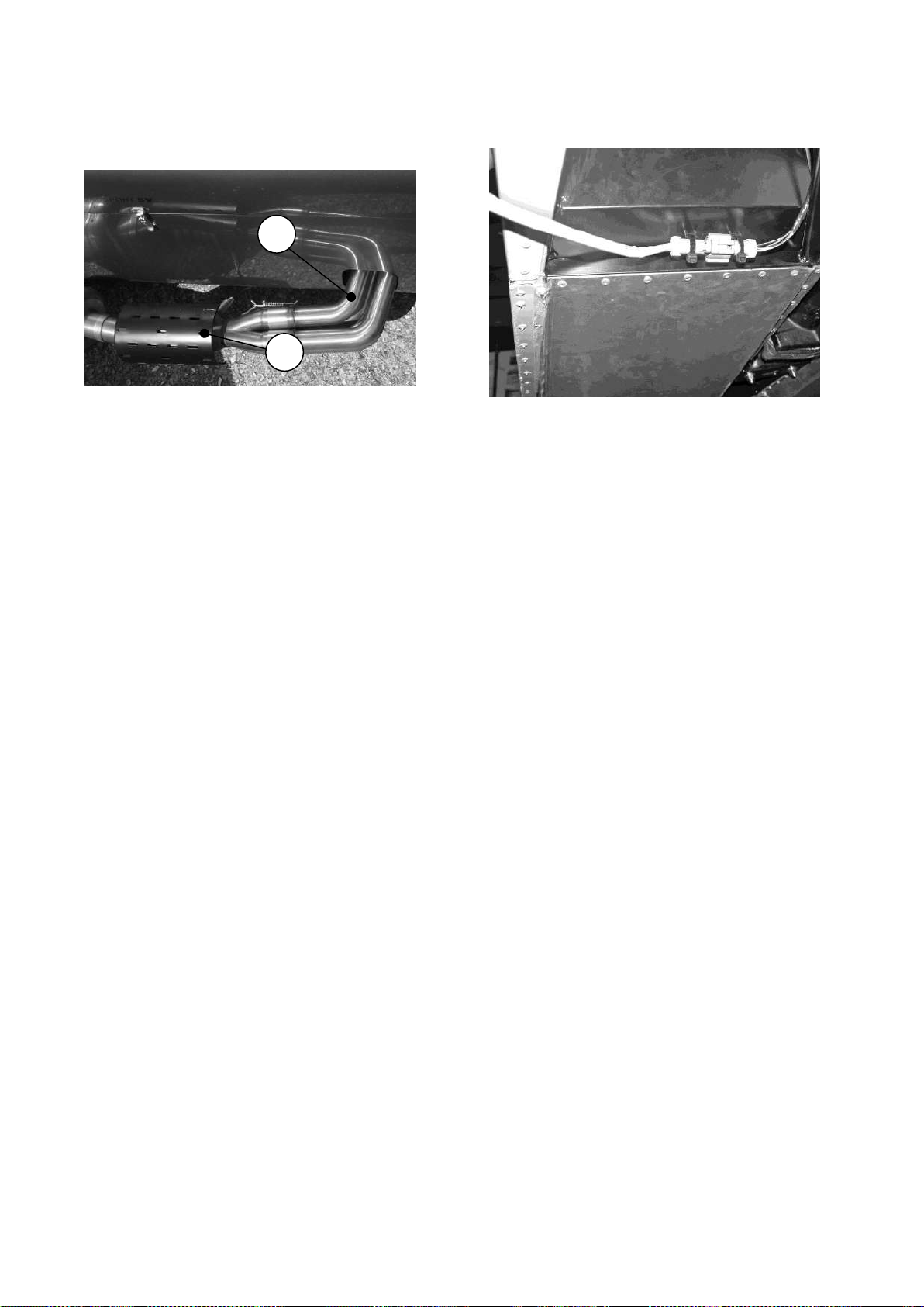
1.Primary pipe
2.Collector/catalyst
1
2
Figure 71: Primary pipes and
collector/catalyst
Fit the Lambda probe into the threaded
hole in the collector/catalyst and connect
Figure 72: Lambda probe connection
Undo the large worm drive clips and feed
them through the channels on the inside
of the collector/catalyst guard. Ensure that
the clip drives are not at the bottom of the
silencer where they could contact the
the probe plug to the corresponding
socket from the engine wiring loom.
Secure the Lambda probe connection and
wiring to the chassis ensuring that it
cannot contact the hot exhaust or any
moving part, refer to Figure 77.
NOTE
The lambda probe wiring passes under
the side of the car below the lower chassis
tube, it must not be routed through the
primary pipe aperture in the side panel.
road.
NOTES
1. For a neater appearance position the
clips with the drive screw towards the
ground so that the clip ‘tail’ is out of sight
beneath the exhaust.
2. To reduce the risk of damage it is
advisable to fit the silencer after the RH
rear wing has been attached.
Page | 98
Page 100
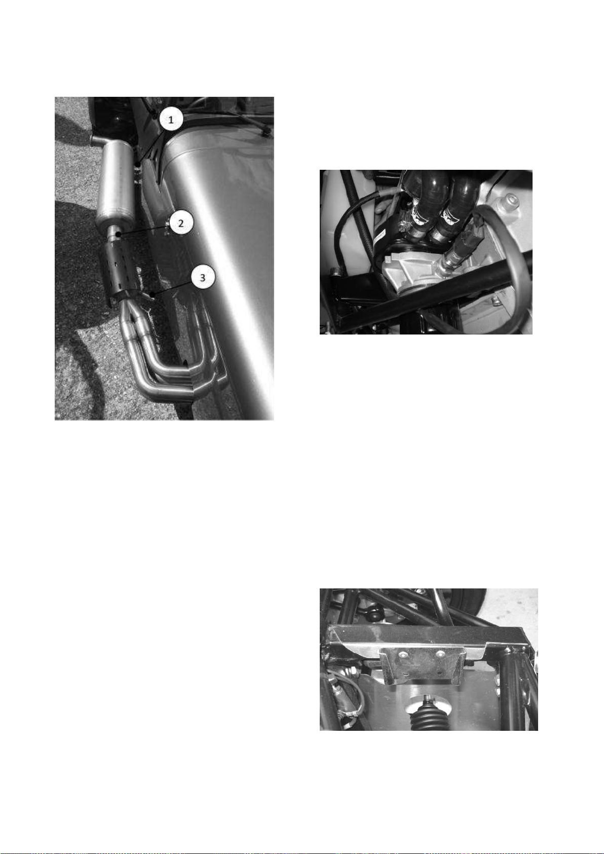
1. Silencer bracket
3. Lambda probe
2. Band clamp
Figure 73: Exhaust arrangement
engine. It enables the engine oil to be
cooled by circulating coolant around the
oil-filled modine cooler.
Figure 74: Location of modine
Position the breather bottle mounting
Loosely fit the single band clamp to the
front of the silencer and position the front
of the silencer over the collector/catalyst
outlet pipe. Locate the bracket at the rear
of the silence over the bobbin on the
silencer mounting bracket and secure with
a nut and spring washer. Tighten the nut
and band clamp. It may be necessary to
bracket on the chassis as shown in the
picture. Align the RHS hole on the bracket
with the RHS rivet on the chassis and
mark both hole. Drill the marked hole with
5/32” drill and fit the bracket in place using
5/32 rivets refer to fig 80. Push fit the
breather bottle on to the mounting
bracket.
Figure 75: Breather bottle mounting
bracket
reposition the guards slightly.
7.2.7) Cooling system
All wet sump Duratec engines have an oil
cooler modine fitted to the RHS of the
Page | 99
 Loading...