

Caterham Seven Owner's Handbook Manual

1
OWNERS HANDBOOK
CONTENTS
Introduction Page
1. Before Taking to the Road 4
Controls 4
Standard instrumentation 4
Explanation of dashboard 5
Stack display with windscreen 6
CSR Integral dash 7
R500 8
Stack display operation 9
Before you drive away 10
Pedal adjustment 10
Seats and seat belts 10
Harness 10
Weather equipment 11
Security 12
Starting the engine 14
Running-in 14
Catalytic convertor 14
Gearbox 15
Fuel 15
Braking system 16
2. Useful Information 17
Engine specification 17
Technical data 18
Track use 20
3. Maintenance 21
Owner maintenance 21
Under bonnet location 21
EU4 Sigma 120 22
Sigma 125 23
Sigma 150 24
Duratec 210 (R400) 25
EU4 Duratec 200 (CSR) 26
Duratec 260 (CSR) 27
Duratec 263 (R500) 28
Safety in the garage 29
Axle stand positioning 29
Checking fluid levels 30
Oil 30
Coolant 31
Brake Fluid 32
Clutch Fluid 32
Windscreen washers 32
Battery 32
Wheels & Tyres 34
Changing a wheel 34
Cleaning and car care 35
Laying your vehicle up for
long periods 36
Travelling abroad 37
4. In an Emergency 37
Emergency starting 37
Emergency towing 38
Fuses & relays 38
Parts & accessories 39
Bulb replacement 39
5. Servicing 41
Service schedules 41
Service & modification record 42
Warranty

2

3
INTRODUCTION
Congratulations on ownership of your new Caterham Seven sports car.
Designed for racing and built for living, your Caterham Seven is competition-developed
and capable of performance well in excess of your average super car. Please take the
time to read this manual, get well acquainted with the controls and understand the
maintenance requirements of your car. This will help you appreciate its capabilities to the
full and allow you to derive maximum pleasure from ownership.
As a high performance car, it is likely that your Caterham will be subjected to the stresses
and strains of enthusiastic driving, particularly on the track. Therefore it is essential that
the maintenance programme of regular servicing and checks contained in this manual is
adhered to. This will ensure that the vehicle is always in the best possible condition and
performing at its optimum. For all servicing we recommend that you return your car to the
Aftersales Department at Caterham Dartford or Caterham Midlands. Alternatively you
may find it more convenient to use one of the Caterham approved service agents located
around the UK.
Using this Handbook
This handbook has been divided into sections, each dealing with the different aspects of
owning and caring for your Caterham. You will find lots of useful and worthwhile advice
and tips to help you get to know and look after your new car.
‘Before Taking to the Road’ – Includes controls, pedal adjustment, seat adjustment,
weather equipment, security and other information that you should know before you
drive your new car.
‘Useful Information’ – This section is where you will find all the technical data on
your Caterham Seven.
‘Maintenance’ – Detailed here are all the regular checks you will need to carry out
to ensure you continue to get the best from your Caterham.
‘In an Emergency’ – Should an emergency arise then here you will find advice on
what you can do, including jump starting, checking the fuses and changing a bulb.
‘Servicing’ – This section provides vehicle service information including service
schedules. In addition you will find pages that can be used to keep a record of when
and where a service took place plus an additional section for any future
modifications or upgrades to your vehicle.
WARNING!
Safety warnings are included in this handbook. These indicate either a procedure which
must be followed precisely, or information that should be considered with great care in
order to avoid the possibility of personal injury or serious damage to the vehicle.

4
1. BEFORE TAKING TO THE ROAD
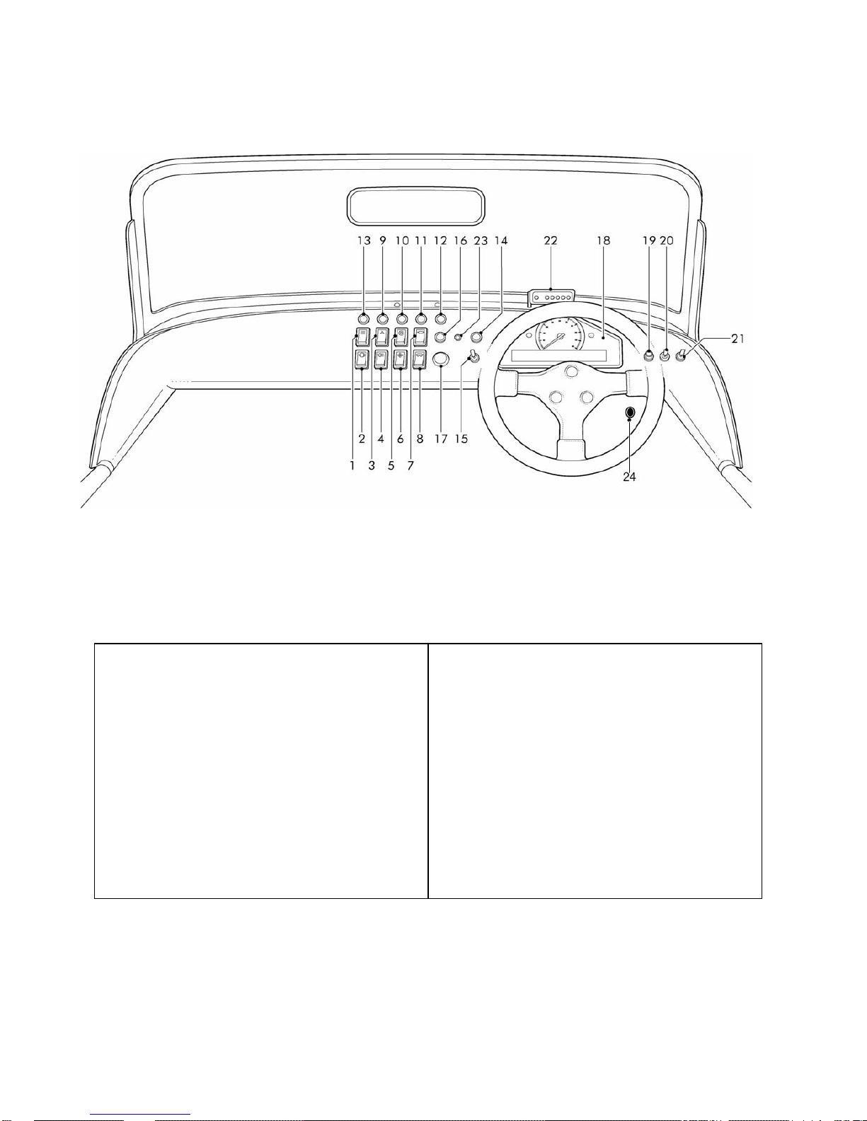
Figure 1: Dashboard layout for models with standard instruments
Figure 1a: Five or six
speed gear shift patterns
Controls
1. Brake fail indicator
2. Hazard warning light switch
3. Rear fog light switch
4. Heated windscreen switch
5. Heater fan switch
6. Immobilizer warning light
7. Windscreen washers switch
8. Windscreen wipers switch
9. Side lights/head lights switch
10. Indicators switch
11. Main beam switch
12. Headlamp flasher switch
13. Horn
14. Fuel gauge
15. Temperature gauge
16. Oil Pressure gauge
17. Tachometer
18. Speedometer
19. main beam warning light
20. Indicator warning light
21. Ignition warning light
22. Push starter button
23. Trip reset button
24. Heater valve control

5
EXPLANATION OF DASHBOARD
Brake fail indicator Single position spring loaded switch, illuminates to indicate low fluid level. Press to test
bulb.
Hazard warning light Single position switch activates all indicators.
Rear fog light Single position switch activates rear fog lights when dipped headlights are illuminated.
Heated windscreen Single position switch activates heating elements to demist front windscreen.
Heater fan Two position switch provides low and high speed fan control.
Windscreen washers Single position spring loaded switch activates washer jets when depressed.
Windscreen wipers 2 position switch to provide low and high speed continuous wipe.
Indicator switch 3 position switch Left-Off-Right (non-self cancelling)
Side/Head lights 2 position switch, first position side lights, second position dipped beam headlight.
Main beam 2 position switch for dip or main beam.
Headlamp flasher Single position spring loaded switch to flash headlights.
Heater valve control This is located on the inside of engine compartment bulkhead, above the driver’s knee.
Pull towards driver to increase heat.
Starter push button Single position spring loaded push switch, press to start engine
Horn push button Single position spring loaded push switch
Speedometer
Indicates road speed in miles per hour and/or
kilometres per hour.
Digital display within speedometer
The display shows the following:
Odometer reading (shows the total distance
travelled by the car).
Trip recorder (for recording individual journey
distances). The word trip is also displayed.
Trip recorder reset button
Whenever the ignition switch is turned on, the display
shows the odometer reading. By pressing the trip
recorder reset button briefly, the display will change to
show the trip recorder reading (a further press of the
button returns the display to the odometer reading).
Press and hold the reset button to reset the display to
zero.
Tachometer
Indicates engine speed in revolutions per minute.
NOTE: An electronic limiter will prevent engine speed
rising above a pre-determined factory set level.
Oil Pressure Gauge
The needle indicates the oil pressure measured in bar.
The needle will quickly rise when the engine is started.
If the needle falls into the Red mark during normal
running the oil pressure is at a critical level and severe
engine damage could result; switch off the engine
immediately (safety permitting) and seek qualified
assistance. (Engine pressure will fluctuate as engine
revs change)
WARNING!
Never restart the engine or drive the car with the oil
pressure gauge indicating red.
Temperature Gauge
Indicates the temperature of the engine coolant. During
normal operation, the needle will rise from the lower
(cold) mark to the middle part of the gauge, where it
will remain while the engine is operating at its normal
temperature.
In severe driving conditions, such as very hot weather
or extended hill climbing, the needle may rise. If the
needle rises to the RED mark, the coolant is too hot
and severe engine damage could result; stop the car
as soon as safety permits and seek qualified
assistance.
Fuel gauge
The needle indicates the fuel level. After refuelling, the
gauge slowly rises to the new level once the ignition
switch is turned on.
WARNING! NEVER allow the car to run out of fuel (the
resultant misfire could destroy the catalytic converter).
WARNING LIGHTS
Battery charging – RED
The light illuminates as a bulb check when the ignition
switch is turned to position ‘II’ and extinguishes as
soon as the engine is running. If it remains on, or
illuminates whilst driving, a fault with the battery
charging system is indicated. Seek qualified
assistance.
Direction indicators – GREEN
The indicator warning light flashes in time with the left
or right direction indicator lights, whenever they are
operated. If the warning light fails to illuminate or
flashes very rapidly, this means that one of the
indicator lights is not operating.
6
Figure 2: Dashboard layout for models with Stack Instruments and full windscreen
Controls
1. Heated windscreen switch
2. Brake fail indicator
3. Hazard warning light switch
4. Rear fog light switch
5. Side/Head lights switch
6. Heater fan switch
7. Windscreen washers switch
8. Windscreen wipers switch
9. Stack button 1
10. Stack button 2
11. Stack button 4
12. Stack button 3
13. Shift light button
14. Indicator warning light
15. Indicator switch
16. Main beam warning light
17. Starter push button
18. Stack display
19. Horn push button
20. Main beam switch
21. Headlamp flasher switch
22. Gear shift lights
23. Immobiliser warning light
24. Heater valve control
7
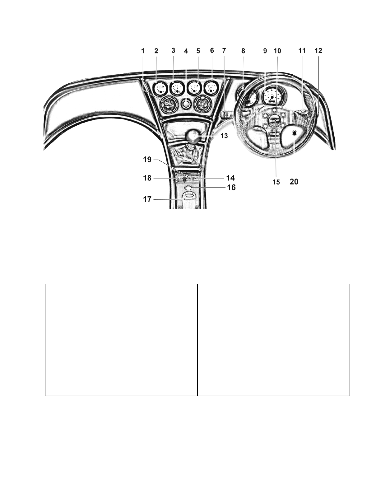
Figure 3: Dashboard layout for CSR with Integral dash
Controls
1. Air vent
2. Oil pressure gauge
3. Temperature gauge
4. Heater fan control switch
5. Fuel gauge
6. Oil temperature gauge
7. Indicators
Side/Head lights
Main beam
Headlamp flasher
8. Tachometer
9. Speedometer
10. Immobilizer warning light
11. Windscreen wipers
Wiper speed control
12. Windscreen washer switch
13. Gear lever
14. Heated screen switch
15. Horn Push button
16. Starter push button
17. Handbrake
18. Rear fog light switch
19. Hazard warning light switch
20. Heater valve control
8
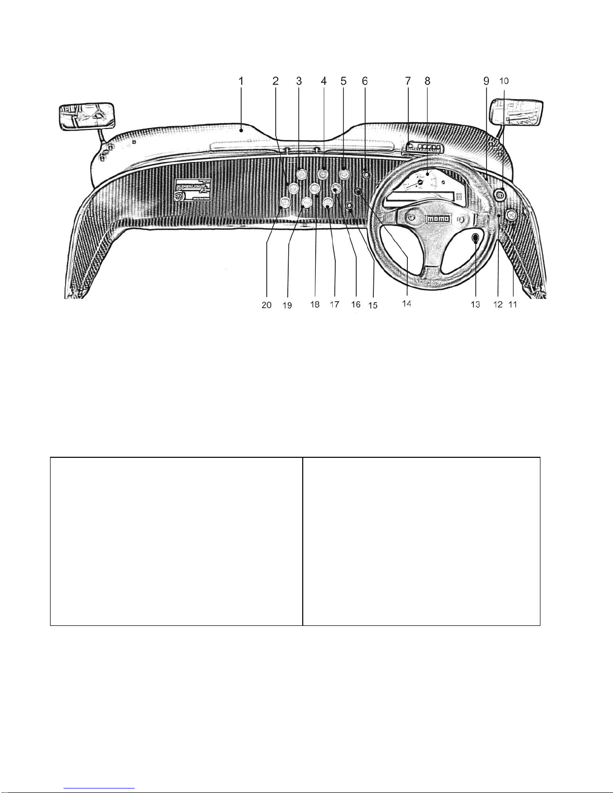
Figure 4: Dashboard layout for R500
NOTE: For full windscreen option the wiring connection to dashboard buttons for heated screen, wipers etc are
already connected.
Controls
1. Aero screen
2. Heated screen switch
3. Hazard warning light switch
4. Windscreen washer switch
5. Windscreen wipers switch
6. Launch control push button
7. Gear shift lights
8. Stack display
9. Stack button 3
10. Main beam switch
11. Side/Head light switch
12. Stack button 4
13. Heater valve control
14. Stack button 2
15. Stack button 1
16. Horn push button
17. Starter push button
18. Rear fog light switch
19. Heater fan switch
20. Brake fail indicator

9
Headlight main beam – BLUE
Illuminates when the headlights are switched to main
beam.
Immobiliser Warning light - Red
See section on Immobilisation.
Stack Display System
The Stack display system combines an analogue
tachometer with a digital display for the following
performance parameters:
1. Vehicle speed
2. Engine speed
3. Oil pressure
4. Oil temperature
5. Water temperature
6. Fuel level
7. Battery Voltage
8. Lap times (optional) available from aftersales.
An alarm light alerts the driver that a warning condition
has been detected. The warning conditions are based
on pre-set alarm values for the above listed
performance parameters 3-7. When the alarm light is
on, a warning message is shown on the digital display
to identify the condition. It is possible to enable or
disable the warning system for each parameter
individually. The warning message can be cancelled by
pressing any switch. Doing this does not turn off the
warning condition alarm light, which stays on until the
condition no longer applies.
The digital display has five screen display options each
showing certain parameters and their values. The
different screen can be changed by pressing button 3.
Screen 1
Fuel level
Current speed
Trip indicator
Odometer
Press button 3 to change to screen 2
Screen 2
Oil temperature
Current speed
Oil pressure
Press button 3 to change to screen 3
Screen 3
Water temperature
Current speed
Oil pressure
Press button 3 to change to screen 4.
Screen 4
Current speed
Battery Voltage
Ambient air temperature is shown but not utilised
in the set-up. This will default to a reading of -999
Press button 3 to change the display to screen 5
Screen 5
Number of current lap
Current speed (mph or km/h)
Last lap time
Previous best lap time
Press button 3 to change the display back to screen 1.
NOTE: The minimum oil and water temperature for
which the display gives a true reading is 12°C or 53°F.
The unit displays temperatures that are less than this
as 0°C or 32°F.
Peak values (Tell Tales)
The system records Max (or Min where appropriate)
values for each parameter, when the engine is running
at more than 1200 rpm.
This is to prevent abnormal peak values from being
recorded when, for example, the engine is either not
running, is idling, or is being warmed up.
Displaying the Peak Values
Press and hold button 1 to show the peak values for
the parameters currently being displayed. Release the
switch to return to the normal display.
Resetting Peak Values
The peak values remain stored until reset. To reset,
press and hold button 1 and then press button 4 as
well. This clears all the peak values & lap times.
Alarms
The display system has built-in warnings to alert the
driver when certain parameters either exceed or fall
below their alarm values.
Displaying an Alarm
When an alarm condition occurs, the built in red
warning light turns on, and the digital display gives a
warning message to show the type of alarm.
NOTE: The amber light indicates low fuel warning.
Clearing an Alarm
Press button 2.
Showing the Last Alarm
Press and hold button 2.

10
Lap Times
The lap time for each lap is recorded either by the
infrared time sensor when passing an optional lap time
beacon or when the driver presses button 4.
The most recent lap time is held in screen 5.
The stack display has an internal battery that needs to
be changed every 4-5 years. When the power from this
battery drops below a safe level, an alarm is triggered
and the warning “Internal Battery Low" is displayed.
Contact Caterham Aftersales when this occurs.
BEFORE YOU DRIVE AWAY
Pedal Adjustment Facility
On some models the pedals may be adjusted to suit
the driver. Please contact your caterham agent for
details. (CSR/EU4 cars does not have this facility)
Seats/Seat belts/Harness
Forward/backward adjustment
Push the seat adjustment lever to one side to release
the catch enabling the seat to slide back or forward.
Ensure the seat is locked in position before driving off.
WARNING!
DO NOT adjust the seat while the car is in motion.
Head Restraints
Head restraints are designed to restrain rearward
movement of the head in the event of an accident or
sudden stop. On non-race type seats the head
restraints can be removed completely to allow for
fitment of the tonneau cover.
WARNING!
Never drive the car with the head restraints removed.
Seat belt safety
The seat belts supplied with your car are intended for
use by adult sized occupants and must be used by one
occupant ONLY. Seat belts are life saving equipment.
In a collision, unrestrained passengers can be thrown
around inside, or possibly thrown out of the car,
resulting in injury to themselves and to other
occupants.
ENSURE that the passenger is securely strapped in
at all times.
• ALWAYS adjust seat belts to eliminate any slack
in the webbing. DO NOT slacken the webbing by
pulling the belt away from the body – to be fully
effective, the seat belt must remain in full contact
with the body at all times.
• ALWAYS fit the lap strap across the pelvis (never
across the abdomen), and ensure that the
diagonal strap passes across the chest, without
slipping off the shoulder, or pressing against the
neck.
• DO NOT fit more than one person into a belt, or
use a seat belt that is twisted or obstructed in any
way that could impede its smooth operation.
• DO NOT wear seat belts over hard or fragile items
in clothing, such as pens, keys, spectacles etc.
• DO NOT allow a baby or infant to be carried on
the lap. The force of a crash can increase effective
body weight by as much as 30 times, making it
impossible to hold on to the child.
• DO NOT allow foreign matter to enter the seat belt
buckles as this can render the buckles inoperative.
• Pregnant women should ask their doctor for
advice about the safest way to wear seat belts.
Caring for seat belts
Regularly inspect the belt webbing for signs of fraying,
cuts and wear, also paying particular attention to the
condition of the fixing points and adjusters.
Care should be taken to avoid contamination of the
webbing from the effects of polish, oil and chemicals
(see ‘Cleaning & car care’).
Three tests for checking seat belts
1) With the seat belt fastened, give the webbing near
the buckle a quick upward pull – the buckle should
remain securely locked!
2) With the seat belt unfastened, unreel the webbing to
the limit of its travel. Check that unreeling is free from
snatches and snags.
3) With the webbing half unreeled, hold the tongue
plate and give it a quick forward pull – the mechanism
must lock automatically and prevent any further
unreeling!
WARNING!
Always replace a seat belt assembly that has withstood
the strain of a severe vehicle impact, or one where the
webbing shows signs of fraying.
Harness
A multi-point harness holds the driver firmly in the seat
at all times (unlike a seatbelt which ‘locks’ on impact
only). Aside from the increased safety benefit and
being held more securely in extreme circumstances
such as a trackday driving, a harness will remove the
tendency for the driver to brace themselves in corners
using the steering wheel, with better control of the car
as a result.
The lap strap is engaged first, ensuring that it is
adjusted so that it sits across the lap at the lowest
point. It should tight enough that it requires effort to
engage. Shoulder straps are then engaged into the
appropriate slot and tightened by pulling on the
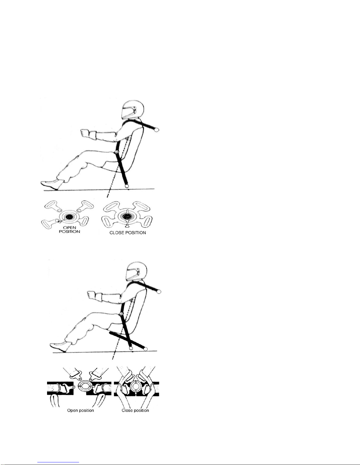
11
adjuster strap. A harness should feel tight when warn
and not allow any movement of the torso. Although
this feels restrictive at first, a driver will quickly get
used to and ultimately prefer this feeling in a Seven.
To exit from the harness, the spring loaded buckle is
rotated 90deg
Figure 5: 4-Point Harness
Figure 6: 6-Point Harness
Harness Adjustment
Slide the tail strap web through the metal three bar
slide to set up the perfect strap length. The shoulder
strap adjusters should sit on the breast bone, by doing
this first you will ensure that the comfort pads are
located in the correct position tighten the lap straps first
making sure the release buckle is in a central position,
final adjustment is taken up by pulling down on the
shoulder straps.
WARNINGS!
Always check your harness regularly for chaffing, stitch
damage or hardware corrosion. Pay particular attention
to areas that may be visible such as under seat or
cowlings, petrol, battery acid, bleach or similar solvent
must not spill onto web.
Always wear your harness as tight as comfort will allow
but no tight that loss of circulation occurs.
Always replaces a harness that has been involved in
an accident or damage has taken place
Never make any changes to your system either by
cutting and re-sewing web or by modifying the
hardware
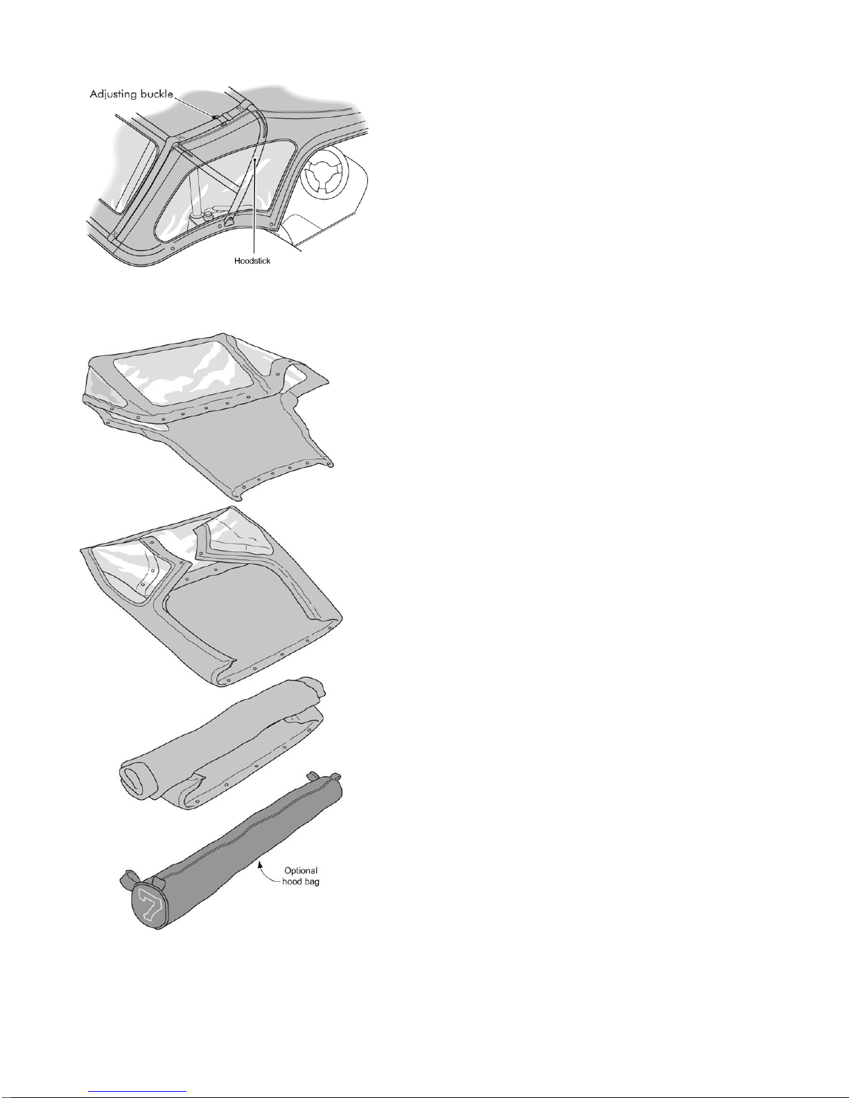
Weather equipment
Erecting the hood is relatively straightforward if the
correct procedure is followed. Therefore we
recommend the following sequence is adopted:i) Erect the hoodsticks slacken the buckles to allow
the front hoodsticks to collapse forwards.
ii) Unfold the hood and clip it onto the windscreen
first.
iii) Stretch the rear of the hood over the back of the
car and clip it over the poppers situated on the
back panel starting at the outside and working into
the centre.
iv) Attach to the remaining poppers on the sides of
the vehicle.
v) From the inside of the car, tension the hood by
pulling on the loose end of the straps retensioning
the buckle (the buckle will automatically lock in
position when released). The straps should be
adjusted until the front hoodstick is in line with the
hood seam. (See Fig 6)
12
Figure 7: Tensioning the hood
Figure 8: Hood folding procedure
vi) The Velcro lined strips inside the hood should now
capture the front hoodstick, which prevents the
hood from ballooning at speed.
vii) The tops of the sidescreens tuck under the flaps
on the hood sides in order to make the hood
watertight. At the rear, however, the sidescreens
overlap the hood.
Removal and storage
To remove the hood slacken the buckles and remove
in reverse to the above. (Vii to i)
It is important that the hood is folded correctly when
removed in order to avoid unsightly creases and to
prevent the clear plastic windows being scratched. We
suggest that it is always folded and then rolled as
shown in Fig 7.
To help prevent damage, and free up storage space, a
protective hood bag is available from Caterham Cars
Parts Counter.
NOTE: Never store the hood when wet.
Security
Keys/key numbers
You have been supplied with 4 keys: 2 for the ignition
and 2 for the fuel cap. The numbers for these can be
found on a small tag attached to the key ring.
You will also have been supplied with 2 coded
transponder tags.
WARNING!
Keep the key tag and spare key in a safe place – NOT
IN THE CAR!
If the key or tag is lost please contact Caterham Cars
to make arrangements for a additional keys and tags.
Immobilisation
Most Caterhams are fitted with an immobiliser as
standard, this will be Sterling Excel vehicle immobiliser
system.
Disarming the system
Insert your ignition key with the transponder unit
attached to the same key ring and the reader unit will
automatically recognise the transponder and disarm
your immobiliser. The LED will stop flashing and turn a
constant red indicating the vehicle can be started
Arming the system
When the vehicle’s ignition is switched off and the keys
are removed from the ignition, the immobiliser will
prepare to arm and the red LED will illuminate. During
this period, the ignition can be switched back on,
cancelling the arming and permitting the vehicle to be
started as normal.
If after twenty seconds the ignition has not been turned
on, then the immobiliser will automatically ‘arm’ and the
red LED will flash. This ‘auto-arming’ sequence means
that it is impossible to leave your vehicle unprotected.

13
WARNING!
Your system will automatically re-arm within twenty
seconds of disarming if you do not turn the ignition on.
Programming new transponder tags
If you require a new transponder tag for an additional
user, or as a replacement through loss or damage,
please contact Caterham Aftersales Department.
Once you have received your new transponder tag,
you will need to programme it. To do this you must
have an existing transponder tag that already operates
the system.
1) Disarm the system using an existing transponder tag
attached to the ignition key.
2) Switch the ignition on and off twice and then turn the
ignition back on, all within 7 seconds (the LED will flash
rapidly).
3) The system will then recognise the transponder tag
on the key ring and re-programme it.
4) The LED will flash once to indicate it recognises the
transponder tag.
5) Remove the ignition key with the transponder tag
attached.
6) Pass a new transponder tag close to the ignition
barrel.
7) The LED will flash twice to indicate that the new
transponder tag is in the memory.
8) Pass any additional transponder tag close to the
ignition barrel.
9) For each transponder tag programmed into the
system the LED will flash a number of times to indicate
how many transponder tags are programmed into the
system.
10) When you have finished, switch the ignition off and
the Sterling Excel will exit the programming mode.
Each time you programme a new transponder tags into
the system it will automatically erase all other
transponder tags in the memory therefore all
transponder tags required to operate the system must
be programmed back in.
NOTE: For EU4 cars the transponder is in the key, if
you require a new transponder as a replacement
through loss or damage please contact your local ford
dealer.
Deleting lost transponder tags from the system
memory
If you lose one of your transponder tags, your vehicle
is no longer totally secure, as anyone who finds your
lost transponder tag could disarm your immobiliser. To
prevent this from happening you are able to delete
transponder tags from the system.
Because your Sterling Excel system will recognise up
to five different transponder tags, you will have to reprogramme all of your existing transponder tags every
time you enter programming mode.
NOTE: Sterling Excel is an electronic immobiliser and
derives its main power from your car battery. However,
the consumption in the armed state is such that it
should not adversely affect your car battery.
WARNING!
The tags contain delicate electronic circuits and must
be protected from impact and water damage, high
temperatures and humidity, direct sunlight, effects of
solvents, waxes and abrasive cleaners.
Vehicle battery disconnection
If the car battery is disconnected for any reason the
status of the security system prior to disconnection will
be memorised and automatically reset when the
battery is reconnected.
Ignition Switch and Steering Lock
The ignition switch uses the following sequence of key
positions to operate the steering lock, electrical circuits
and starter motor:
‘O’ – Steering locked
With the key removed, the steering column will be
locked and most electrical circuits are non-operational.
‘I’ – Steering unlocked
Turn the switch to position ‘I’ to unlock the steering.
‘II’ – Electrical circuits on
With the switch in position ‘II’ all electrical circuits are
operational.
‘III’ – Starter motor operates
Turn the switch to position ‘III’ to operate the starter
motor; release the key as soon as the engine starts
(the key will automatically return to position ‘II’).
Steering Lock
To unlock the steering:
Insert the key FULLY and turn the ignition switch to
position ‘I’ – a small movement of the steering wheel
may be necessary to disengage the lock.
To lock the steering:
With the ignition switch turned to position ‘O’, remove
the key and turn the steering wheel until the lock
engages.
NOTE: Cars fitted with a quick release steering wheel
do not have a steering lock mechanism.
WARNING!
Once the steering lock is engaged it is impossible to
steer the car.
DO NOT remove the key, or turn the ignition switch to
position ‘O’ while the car is in motion.

14
Starting the engine
WARNING!
Before starting the engine ENSURE you are familiar
with the procedures below. Catalytic converters are
easily damaged through improper use, particularly if
the wrong fuel is used or if an engine misfire occurs –
before starting the engine you should be aware of the
precautions detailed in the ‘Catalytic converter’ section.
Never start or leave the engine running in an
unventilated building – exhaust gases are poisonous
and contain carbon monoxide which can cause
unconsciousness and may even be fatal.
Starting the engine:
1) Check that the handbrake is on and that the gear
lever is in neutral.
2) Switch off all unnecessary electrical equipment.
3) Turn the ignition switch to position ‘II’ and release
the key as soon as the engine has started.
NOTE: For cars fitted with a push button start, turn the
ignition switch to position ‘II’ and press the red push
button and release the button as soon as the engine
starts.
WARNING!
DO NOT press the accelerator pedal while starting and
DO NOT operate the starter for more than 15 seconds
at a time. If the engine fails to start switch off and wait
for at least 10 seconds before trying again.
NOTE: When the battery is in a low state of charge,
depress the clutch before starting and hold it down until
the engine is running.
Starting in cold climates
In freezing conditions, fully depress the clutch pedal
while starting and hold it down until the engine is
running. Note that engine cranking times will increase
and that the battery charging light may take several
seconds to extinguish.
Warming up
In the interest of fuel economy, it is advisable to drive
the car soon after starting, remembering that harsh
acceleration or labouring the engine before the normal
operating temperature has been reached can damage
the engine.
Running-In
The engine, gearbox, brakes and tyres need time to
‘bed-in’ and adjust to the demands of everyday
motoring. During the first 500 miles (1,000 km) it is
essential that you drive with consideration for the
running-in process and heed the following advice:
DO NOT allow the engine to exceed 4,000
rev/min in any gear.
DO NOT operate at full throttle in any gear.
DO NOT allow the engine to labour in any gear.
AVOID heavy braking.
After the running-in distance has been completed,
engine speeds may be gradually increased.
Catalytic Converter
The exhaust system on your car incorporates a
catalytic converter, which converts poisonous exhaust
emissions from the engine into environmentally less
harmful gases, thereby reducing atmospheric pollution.
WARNING!
The catalytic converter can be easily damaged through
improper use, particularly if the wrong fuel is used. For
this reason, it is VERY IMPORTANT that you heed the
following precautions:
Filling up with fuel:
Use ONLY fuel recommended for your car (see
Technical Data).
Starting the engine:
WARNING!
DO NOT continue operating the starter if the engine
fails to start after a few attempts (unburnt fuel may be
drawn into the exhaust system, thereby damaging a
catalyst) – seek qualified assistance.
If a misfire is suspected when starting, DO NOT drive
the car or attempt to clear the misfire by pressing the
accelerator pedal. DO NOT attempt to push or tow
start the car. Instead, turn the ignition switch off
immediately and seek qualified assistance.
Driving the car:
Provided the engine has reached its normal operating
temperature, if a misfire is suspected or the car lacks
power while driving, it may be driven SLOWLY (at risk
of catalyst damage) to Caterham Cars for assistance.
Never
Allow the car to run out of fuel (the resultant misfire
could destroy a catalyst).
An engine burning excessive oil (blue smoke from the
exhaust), will progressively reduce catalyst efficiency.
Do not overload the engine.
 Loading...