

Page 1

ASSEMBLY GUIDE
EDITION 1.0
Page 2

ASSEMBLY GUIDE
i
Welcome to your new Caterham kit
Building your own Caterham is immensely rewarding and satisfying. Of course, it should be remembered
that you are building a high performance sports car, not a flat-pack wardrobe, so it will be a little challenging
from time to time; but we’ve set out to make it as easy as possible for anyone, whatever their skill level and
help is just a phone call away.
But before you do anything else, pop the kettle on or pour yourself a G&T with a slice; and
READ THE NEXT THREE PAGES – THEY ARE REALLY IMPORTANT
No, they will not be very exciting unfortunately, but they are important nonetheless and you will regret it later
if you don’t.
ASSEMBLY GUIDE
EDITION 1.0
Your feedback and comments are welcome: [email protected]
Page 3

ASSEMBLY GUIDE ASSEMBLY GUIDE
ii iii
So there are four important things we need to think about NOW before
picking up a spanner:
• This isn't the only guide you'll need
• When to apply for an IVA test
• Photography (no, really)
• Arranging a post build check
Although we have made this guide as comprehensive as possible, the requirements of IVA change from
time to time and even from test centre to test centre. Therefore, it MUST be read in conjunction with the ‘IVA
Checklist Guide’, the latest version of which can be downloaded from the Caterham website. You’ll find the
refer-to-IVA-manual symbol in the bottom of each illustration where attention is required. Reading through
it now, will save pain later! Don’t assume that because you’ve found a reference to one item relating to that
page, it is the only one…
Once you have completed the assembly of your Seven, you are required by law to present it for an ‘Individual
Vehicle Approval’ test (better known as IVA), which is conducted by the Vehicle and Operator Services
Agency (VOSA) at a regional test centre.
We STRONGLY recommend that you apply for your IVA appointment at least a month before you think you
will complete your build, to allow for the application form to be processed at the snail’s pace of bureaucracy.
Once accepted, your IVA application is valid for 6 months and test dates can be changed up to a minimum
of 3 working days prior to your appointment with VOSA (any later and you may incur a charge).
The application form and a guide on how to complete it, is contained within an envelope of documents
provided with your kit and which is probably acting as a coaster for your g&t at the moment. Take this
moment to find it and remove it from the garage and place it somewhere safe (and memorable).
VOSA and the DVLA are a suspicious bunch and in order to register your car, you will need to provide proof
that it is amateur built. When you apply for registration, you will need to include photos from various stages
of you build, which will demonstrate to them that it is an ‘amateur build’.
Recruiting a few extras (your kids, your spouse, the cat, etc.) and some props (last year’s Xmas tree, a radio
from the 1980’s and a rusty bike) will all contribute to a more authentic home-garage feel; proving that no
professional help (i.e. commercial workshop/garage) was involved in the build. Of course, feel free to have
yourself working away on the kit in the photos if one of your ‘extras’ can be trusted with the camera (not the
cat; they never get the exposure right).
Page 4

ASSEMBLY GUIDE
iv v
ASSEMBLY GUIDE
Finally, we know you haven’t started yet, but we need to tell you about the Post Build Inspection now, due to
availability at our service centres and the time it takes to get you a slot. Plan ahead!
What is the Post Build Inspection? This is a free service oered by all Caterham service centres which we
wholeheartedly recommend you take up on prior to your IVA test. It ensures that your car is correctly
assembled and is road-worthy. All safety and operational aspects of your Seven will be checked, concluding
in a road test. This will enable us to advise you of any corrective work that may be required (which we will be
happy to carry out for you*). It is important to note that this is not the same as the IVA test and whilst every
eort will be made to ensure your car passes, there is NO GUARANTEE of a first time IVA pass.
*Obviously any additional work is not for free, but we will speak to you first so you can decide whether you
want to pay us to do the corrections or you want to do them yourself.
REMEMBER: Post Build Inspection slots are in high demand at our service centres and there may be a
two-month lead time at busy times, so please check on availability and book ahead!
All our service centres will be able to oer you a Post Build Inspection and IVA service, where they take the
car to IVA on your behalf. This tends to increase the likelihood of a first time pass and means you don’t need
to take a day out to endure the test, which is beyond dull.
As a guide, the Post Build Inspection through to registration can take around 6 weeks to complete.
That’s it, we’re ready to start assembly
ENJOY
Page 5

ASSEMBLY GUIDE
vi
MY BUILD NOTES
1
HINTS & TIPS
When using a torque wrench, listen/feel the click
and then stop. It does not need to be any tighter
and you might actually weaken the fixing by
‘over‑torquing’ it. Always wind your torque wrench
setting back to free when you’ve finished with it.
John K
A ‘caphead bolt’ has a circular head with a hexagonal drive
inside it. It is tightened with an allen key or hex drive socket.
Capheads are useful where there is limited space around
the head for a spanner or socket. They look nice too!
Richard T
Generally, metric Nyloc nuts have a
blue nylon insert and imperial ones a
white nylon insert.
Grant P
You can tell if you have ‘wide track suspension’ car by looking at the front
dampers. Wide track has a 25mm long hexagonal spacer between the top
spring retainer and the mounting bush.
Matt T
A bolt size is described by its diameter (e.g. M10=10mm)
by the length not including the head (e.g. 65mm).
James A
A ‘spring washer’ has a split in it and squashes up
closed when a fixing is tightened. It is usually used
under a bolt head to help resist it coming undone.
John S
A ‘nyloc’ nut is one with a nylon insert that gets cut by the bolt
thread, making it resistant to unwinding itself. This means that
they should not be repeatedly re‑used.
Chris B
Thread lock is used to stop
something coming undone, but
it only needs a little drop on
the thread to be effective.
Jamie A
Teabag, boiling water, then the milk, in that order.
Simon L
Left and right are as viewed
from the driver’s seat.
Harrison P
1Nm of torque equals 0.736lbft.
Mick F
When using a spanner, always use the ring end wherever
possible. The open end is really only for those times that access
is too limited for a ring spanner or socket.
Mick A
ASSEMBLY GUIDE
Download the IVA Checklist Guide: www.caterhamcars.com
Book IVA Test
Take plenty of photos
Arrange post build check
This was more fun than I ever expected!
Page 6
ASSEMBLY GUIDE ASSEMBLY GUIDE
2 3
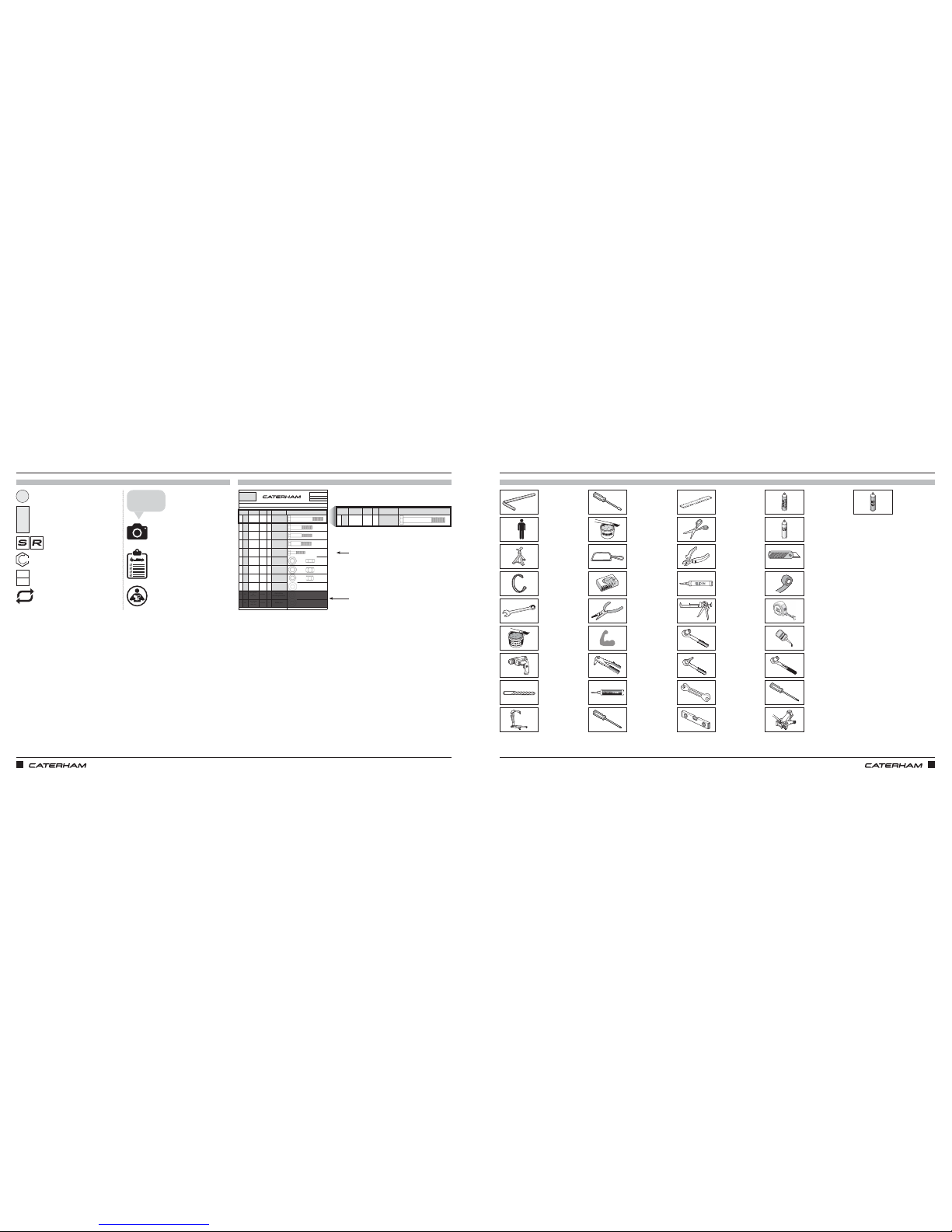
TOOLS
KEY KEY
SYMBOLS
Repeat on other side
Required torque (where applicable)
S3 / S5 chassis specific instructions
S Pack / R Pack
specific instructions
Fixing item
Item number
Advice from factory
professionals
Now is a good time to take
some photos
Reminder to apply for your IVA test
Refer to IVA Checklist Guide
Spanner
Scissors
Grease
Latex gloves
Junior hacksaw
Long nose pliers
Pop rivet gun
Muscle
Pozidrive
screwdriver
Power adhesive
Flat head
screwdriver
Thread lock /
LocTite
LOCTITE
LOCTITE
Tape
Torx
Tape measure
Trolley jack
Torque wrench
WD40
Ruler
Side cutters
Silicon gun
Silicon
Socket wrench
Spray adhesive
Spray lube
Socket wrench
(allen)
Stanley knife
Spirit level
AA
AJ
AM
S3
S5
Nm
1
FIXINGS
PART
NUMBER
QTYUSED ON
1AA
BM12X100
2
Lower wishbone
rear
2AB
BM12X65
2
Lower wishbone
front
3AC
BM10X65
2
Upper wishbone
rear
4AD
BM10X60
2
Upper wishbone
front
5AE
BM8X40
4
Anti-roll bar
mounting brackets
6AF
NMPH14
1
Temporary use to
help lock upper
wishbone ball joint
7AG
NMYF12
2
Lower wishbone
rear
8AH
NMYF10
4
Upper wishbone
9AJ
WPCM12
18
Lower wishbone
10 AK
WPHM8
4
Anti-roll bar
mounting brackets
11 AL
WPH3/8
2
Brake pipe
Drawings are for illustrative purposes only and are not to scale.
A
SERIAL
NUMBER
44
Pack
PACK NUMBER
30F015B
FRONT SUSPENSION DeDION CARS (METRIC)
This pack may include extra fasteners to cover different options
ITEM
BASIC
DESCRIPTION
ILLUSTRATION
Bolt M12 x 100
Grade 10.9
Bolt M12 x 65
Grade 10.9
Bolt M10 x 65
Grade 10.9
Bolt M10 x 60
Grade 10.9
Bolt M8 x 40
Grade 10.9
Plain Nut M14
x 1.5 thread
Nyloc Nut M12
Plain Washer
⅜" x ¾"
Heavy duty
Page 1 of 2
Nyloc Nut M10
Plain Washer
M12
Chamfered
Plain Washer
M8
Heavy duty
PART
NUMBER
QTYUSED ON
1AA
BM12X100
2
Lower wishbone
rear
A
SERIAL
NUMBER
44
Pack
PACK NUMBER
30F015B
FRONT SUSPENSION DeDION CARS (METRIC)
This pack may include extra fasteners to cover different options
ITEM
BASIC
DESCRIPTION
ILLUSTRATION
Bolt M12 x 100
Grade 10.9
x4 (Indicates number of each fixing required)
(Greyed out area indicates fixings are not
required for current step)
Drill bit
Axle stand
Combination
spanner
Allen key
Engine hoist
Copper grease
Drill
Cable tie
Assistance
+
REPEAT
Page 7
ASSEMBLY GUIDE ASSEMBLY GUIDE
4 5
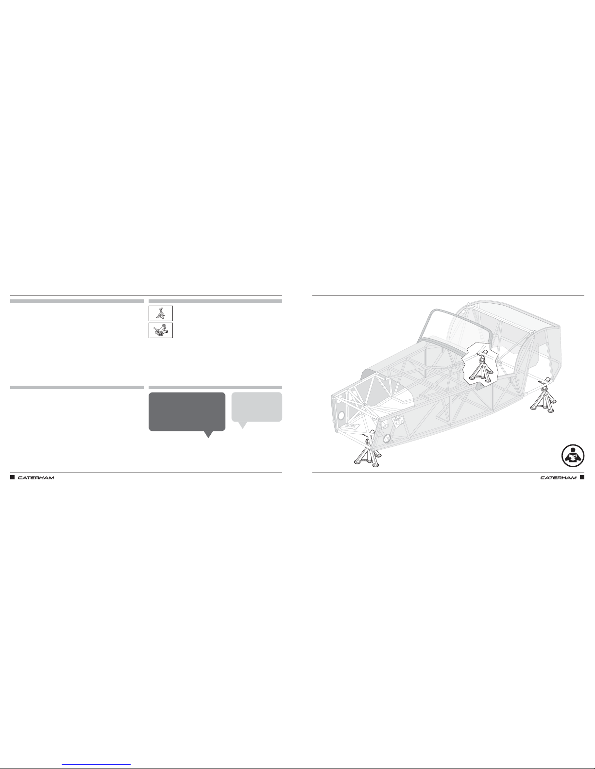
LET’S GET READYLET’S GET READY
PARTS
FIXINGS
TOOLS
TIPS
x3
When deciding how high your axle stands
should be (the higher the better for working
on), don’t forget that a complete car will
need to come down off them, so make sure
your trolley jack can reach and lift the
height you set them too!
Mick F
Some tape or foam on the
top of the axle stands will
stop them scratching the
chassis.
Matt T
Page 8
ASSEMBLY GUIDE ASSEMBLY GUIDE
6 7
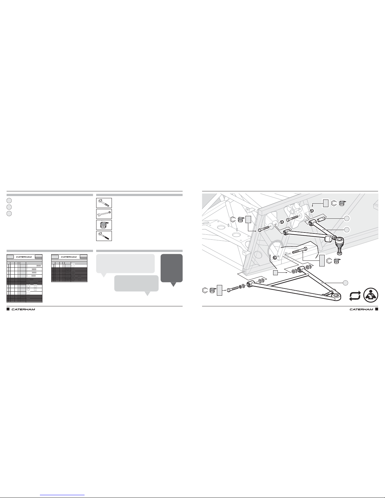
START WITH THE SUSPENSION WISHBONESSTART WITH THE SUSPENSION WISHBONES
PARTS
FIXINGS
TOOLS
TIPS
PART
NUMBER
QTYUSED ON
1AA
BM12X100
2
Lower wishbone
rear
2AB
BM12X65
2
Lower wishbone
front
3AC
BM10X65
2
Upper wishbone
rear
4AD
BM10X60
2
Upper wishbone
front
5AE
BM8X40
4
Anti-roll bar
mounting brackets
6AF
NMPH14
1
Temporary use to
help lock upper
wishbone ball joint
7AG
NMYF12
2
Lower wishbone
rear
8AH
NMYF10
4
Upper wishbone
9AJ
WPCM12
18
Lower wishbone
10 AK
WPHM8
4
Anti-roll bar
mounting brackets
11 AL
WPH3/8
2
Brake pipe
Drawings are for illustrative purposes only and are not to scale.
A
SERIAL
NUMBER
44
Pack
PACK NUMBER
30F015B
FRONT SUSPENSION DeDION CARS (METRIC)
This pack may include extra fasteners to cover different options
ITEM
BASIC
DESCRIPTION
ILLUSTRATION
Bolt M12 x 100
Grade 10.9
Bolt M12 x 65
Grade 10.9
Bolt M10 x 65
Grade 10.9
Bolt M10 x 60
Grade 10.9
Bolt M8 x 40
Grade 10.9
Plain Nut M14
x 1.5 thread
Nyloc Nut M12
Plain Washer
⅜" x ¾"
Heavy duty
Page 1 of 2
Nyloc Nut M10
Plain Washer
M12
Chamfered
Plain Washer
M8
Heavy duty
94
PART
NUMBER
QTYUSED ON
12 AM
WSHM12
2
Lower wishbone
front
13 AN
WSHM8
6
Anti-roll bar
mounting brackets &
upper damper
mount
14 AP
WSS3/8
2 Brake pipe
15 AR
NFYH1/2
2Wing stay
16 AS
NFYF1/2
2
Front brake, upright
mounting (std track
ONLY)
Drawings are for illustrative purposes only and are not to scale.
A
SERIAL
NUMBER
44
Pack
PACK NUMBER
30F015B
FRONT SUSPENSION DeDION CARS (METRIC)
This pack may include extra fasteners to cover different options
ITEM
BASIC
DESCRIPTION
ILLUSTRATION
Spring Washer
M12
Nyloc Nut ½"
Full height
Page 2 of 2
Spring Washer
M8
Washer ⅜"
Shake-proof
Nyloc Nut ½"
Half height
x2
x2
x2
x2
x2
x4
x14
x2
17mm
19mm
Lower wishbone
Wishbone bush sleeve
Upper wishbone
17mm
19mm
1
3
2
For now, only tighten the nuts/bolts lightly and then
torque them up when the car is finished and on the
ground. This sets the bushes correctly and ensures
the best handling.
Harrison P
The big washers are chamfered and
the chamfered side should be towards
the wishbone.
Alex H
Leave bolt AD
loose for now,
as we have to
take it back out
again to put
the headlight
bracket on later.
John K
81Nm
AB
AJ
AM
1
2
3
AJ
81Nm
AA
AJ
AG
47Nm
47Nm
AD
AH
AC
AH
REPEAT
Page 9
ASSEMBLY GUIDE ASSEMBLY GUIDE
8 9
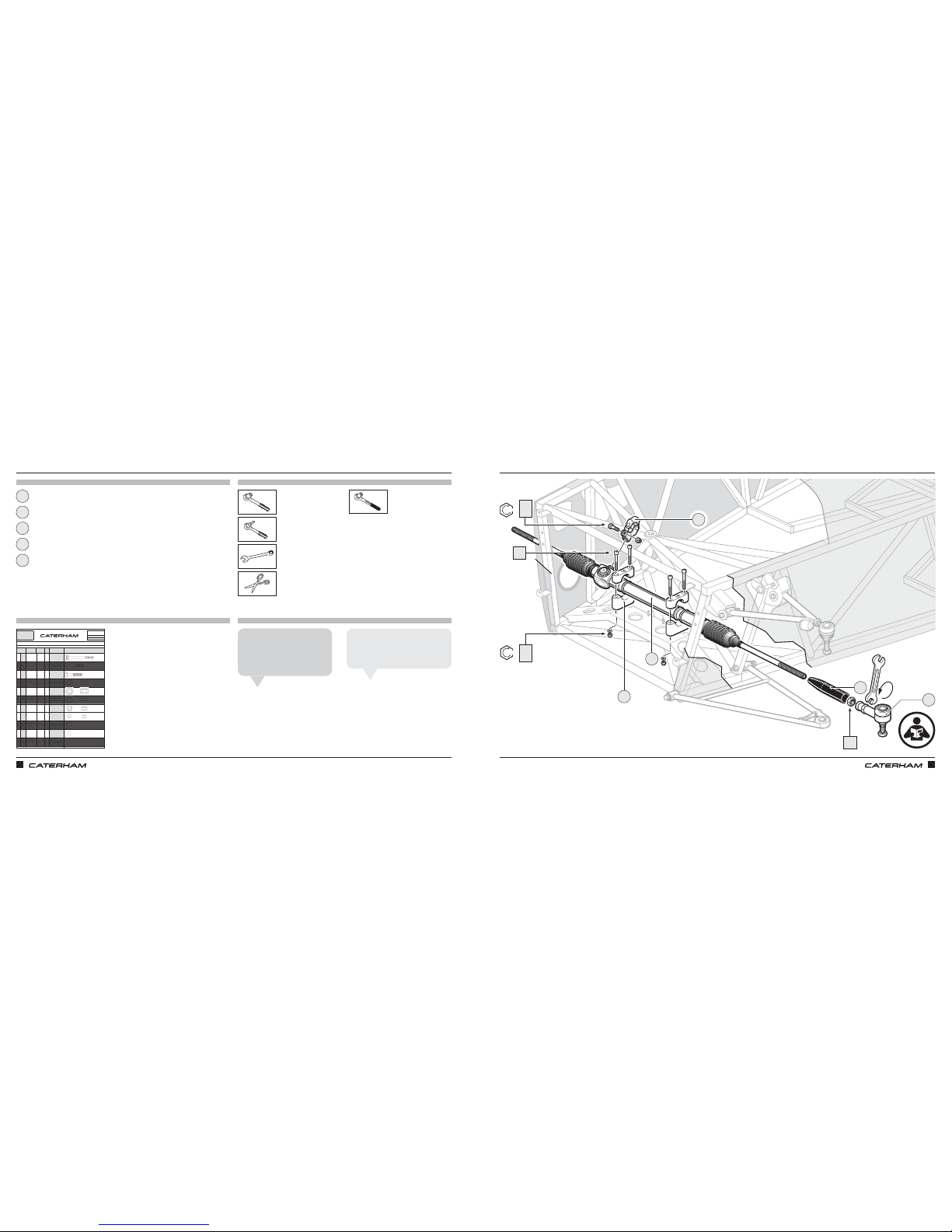
NOW FOR THE STEERING RACKNOW FOR THE STEERING RACK
PARTS
FIXINGS
TOOLS
TIPS
PART
NUMBER
QTYUSED ON
1BA
BMCH6X70
4Rack clamps
2BB
BF1/4X1.1/2
2Column clamp
3BC
BM8X35
2
Column to rack
universal joint
4BD
NFYH1/2
1Steering wheel boss
5BE
NFPF1/2
2Track rod lock nut
6BF
NFPFH7/16
1
Column clamp
grubscrew locknut
7BG
NMYF8
2
Column to rack
universal joint
8BH
NMYF6
4
Steering rack
clamps
9BJ
WPH1/2
1
Steering wheel boss
10 BK
WPH1/4
6
Rack clamps and
column clamp
11 BL
WSH1/4
2
Column clamp
Drawings are for illustrative purposes only and are not to scale.
B
SERIAL
NUMBER
55
Pack
PACK NUMBER
30S003B
STEERING DeDION CARS (METRIC)
This pack may include extra fasteners to cover different options
ITEM
BASIC
DESCRIPTION
ILLUSTRATION
Caphead Bolt
M6 x 70
DIN 912
Bolt ¼" x 1½"
Bolt M8 x 35
Grade 8.8
Nyloc Nut ½"
Half height
Plain Nut ½"
Plain Nut ⁷⁄₁₆"
Half height
Nyloc Nut M8
Spring Washer ¼
Heavy duty
Page 1 of 1
Nyloc Nut M6
Plain Washer
½" x 1⅛"
Chamfered
Plain Washer
¼"
Heavy duty
x4
x2
x2
x2
x4
x4
10mm
13mm
Steering rack
Column universal joint
Rack clamps
IVA cover
Track rod end
5mm
13mm
22mm
¾"
1
3
2
5
4
Finding the right IVA cover isn’t
obvious because it is effectively
a long cap. To use it, you cut the
closed end off.
Jamie A
The trackrod end needs to screw on
about 12 turns (it will be properly set
later when the tracking is done).
Matthew H
11Nm
BE
3
5
20Nm
BC
BG
BH
BK
BA
2
1
4
Page 10
ASSEMBLY GUIDE ASSEMBLY GUIDE
10 11
PART
NUMBER
QTYUSED ON
1AA
BM12X100
2
Lower wishbone
rear
2AB
BM12X65
2
Lower wishbone
front
3AC
BM10X65
2
Upper wishbone
rear
4AD
BM10X60
2
Upper wishbone
front
5AE
BM8X40
4
Anti-roll bar
mounting brackets
6AF
NMPH14
1
Temporary use to
help lock upper
wishbone ball joint
7AG
NMYF12
2
Lower wishbone
rear
8AH
NMYF10
4
Upper wishbone
9AJ
WPCM12
18
Lower wishbone
10 AK
WPHM8
4
Anti-roll bar
mounting brackets
11 AL
WPH3/8
2
Brake pipe
Drawings are for illustrative purposes only and are not to scale.
A
SERIAL
NUMBER
44
Pack
PACK NUMBER
30F015B
FRONT SUSPENSION DeDION CARS (METRIC)
This pack may include extra fasteners to cover different options
ITEM
BASIC
DESCRIPTION
ILLUSTRATION
Bolt M12 x 100
Grade 10.9
Bolt M12 x 65
Grade 10.9
Bolt M10 x 65
Grade 10.9
Bolt M10 x 60
Grade 10.9
Bolt M8 x 40
Grade 10.9
Plain Nut M14
x 1.5 thread
Nyloc Nut M12
Plain Washer
⅜" x ¾"
Heavy duty
Page 1 of 2
Nyloc Nut M10
Plain Washer
M12
Chamfered
Plain Washer
M8
Heavy duty
94
PART
NUMBER
QTYUSED ON
12 AM
WSHM12
2
Lower wishbone
front
13 AN
WSHM8
6
Anti-roll bar
mounting brackets &
upper damper
mount
14 AP
WSS3/8
2 Brake pipe
15 AR
NFYH1/2
2Wing stay
16 AS
NFYF1/2
2
Front brake, upright
mounting (std track
ONLY)
Drawings are for illustrative purposes only and are not to scale.
A
SERIAL
NUMBER
44
Pack
PACK NUMBER
30F015B
FRONT SUSPENSION DeDION CARS (METRIC)
This pack may include extra fasteners to cover different options
ITEM
BASIC
DESCRIPTION
ILLUSTRATION
Spring Washer
M12
Nyloc Nut ½"
Full height
Page 2 of 2
Spring Washer
M8
Washer ⅜"
Shake-proof
Nyloc Nut ½"
Half height
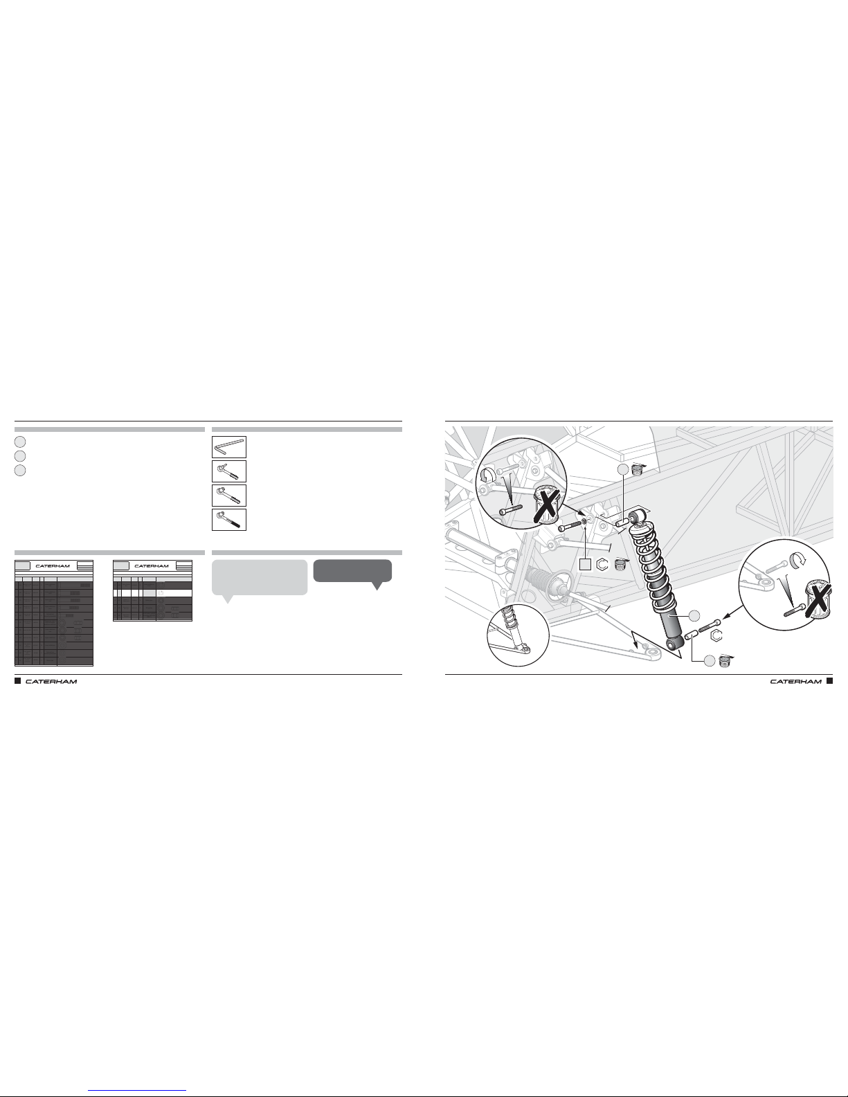
AND THEN THE DAMPERSAND THEN THE DAMPERS
PARTS
FIXINGS
TOOLS
TIPS
6mm
Spring / damper
Upper damper eyelet
Lower damper eyelet
6mm
6mm
1
3
2
Put the top of the damper on first
and be careful not to let it swing into
the side of the chassis.
Grant P
The bottom can be a tight fit!
Mick F
x2
Fixings not contained in the pack will be
supplied loosely fitted to the chassis and
the wishbone
25Nm
1
2
3
25Nm
AN
Page 11
ASSEMBLY GUIDE
12 13
PART
NUMBER
QTYUSED ON
1AA
BM12X100
2
Lower wishbone
rear
2AB
BM12X65
2
Lower wishbone
front
3AC
BM10X65
2
Upper wishbone
rear
4AD
BM10X60
2
Upper wishbone
front
5AE
BM8X40
4
Anti-roll bar
mounting brackets
6AF
NMPH14
1
Temporary use to
help lock upper
wishbone ball joint
7AG
NMYF12
2
Lower wishbone
rear
8AH
NMYF10
4
Upper wishbone
9AJ
WPCM12
18
Lower wishbone
10 AK
WPHM8
4
Anti-roll bar
mounting brackets
11 AL
WPH3/8
2
Brake pipe
Drawings are for illustrative purposes only and are not to scale.
A
SERIAL
NUMBER
44
Pack
PACK NUMBER
30F015B
FRONT SUSPENSION DeDION CARS (METRIC)
This pack may include extra fasteners to cover different options
ITEM
BASIC
DESCRIPTION
ILLUSTRATION
Bolt M12 x 100
Grade 10.9
Bolt M12 x 65
Grade 10.9
Bolt M10 x 65
Grade 10.9
Bolt M10 x 60
Grade 10.9
Bolt M8 x 40
Grade 10.9
Plain Nut M14
x 1.5 thread
Nyloc Nut M12
Plain Washer
⅜" x ¾"
Heavy duty
Page 1 of 2
Nyloc Nut M10
Plain Washer
M12
Chamfered
Plain Washer
M8
Heavy duty
94
PART
NUMBER
QTYUSED ON
12 AM
WSHM12
2
Lower wishbone
front
13 AN
WSHM8
6
Anti-roll bar
mounting brackets &
upper damper
mount
14 AP
WSS3/8
2 Brake pipe
15 AR
NFYH1/2
2Wing stay
16 AS
NFYF1/2
2
Front brake, upright
mounting (std track
ONLY)
Drawings are for illustrative purposes only and are not to scale.
A
SERIAL
NUMBER
44
Pack
PACK NUMBER
30F015B
FRONT SUSPENSION DeDION CARS (METRIC)
This pack may include extra fasteners to cover different options
ITEM
BASIC
DESCRIPTION
ILLUSTRATION
Spring Washer
M12
Nyloc Nut ½"
Full height
Page 2 of 2
Spring Washer
M8
Washer ⅜"
Shake-proof
Nyloc Nut ½"
Half height
ASSEMBLY GUIDE
1 x ⅛
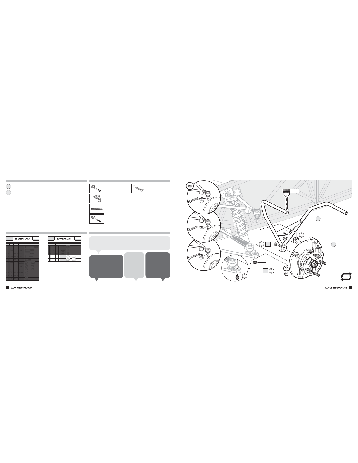
IT’S TIME FOR THE WINGSTAYSIT’S TIME FOR THE WINGSTAYS
PARTS
FIXINGS
TOOLS
TIPS
19mm
22mm
¾"
22mm
Wingstay
Front brake & upright assembly
x2
x2
1
2
WIDE
TRACK
54Nm
81Nm
61Nm
AS
AR
STANDARD TRACK
Some of the fixings
required and shown
on the drawings,
such as the ball
joint nut, are already
on the part and not
in the fixing pack.
Anthony L
Use the plain
nut to pull the
top ball joint
home before
using a nyloc,
otherwise the
thread will spin.
Chris N
The drilled hole is for the side repeater earth that we’ll fit later. It’s easier to
drill from the top and down through both sides of the tube, rather than through
one side from the bottom (where the earth will be fixed).
Tiago O
Put the ‘upright’ into the lower
wishbone joint then attach
the steering before tightening
the bottom nut. This stops it
all swinging around hitting the
side of the chassis.
John S
1
2
"
REPEAT
54Nm
Page 12

ASSEMBLY GUIDE
14 15
Have you applied for your IVA yet?Now is a good time to take some photos
ASSEMBLY GUIDE
Page 13
ASSEMBLY GUIDE ASSEMBLY GUIDE
16 17
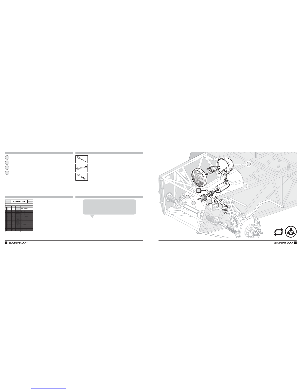
LET THERE BE LIGHTS
7
7
LET THERE BE LIGHTS
PARTS
FIXINGS
TOOLS
TIPS
PART
NUMBER
QTYUSED ON
1CA
71080
6
Indictor assembly to
indicator pod
2CB
71077
2
Side repeater earth
on wingstay
3CC
71079
4
Rear light cluster
upper fixing
4CD
71078
4
Rear light cluster
lower fixing
5CE
NMYF6
2
Horn bracket to
steering rack
platform
(160/270/310)
6CF
WPH1/4
2
Horn bracket to
steering rack
platform
(160/270/310)
7CG
BM8X50
1
Through steering
rack platform &
spacer
(420)
8CH
WPH5/16
2Bolt head/nut
9CI
NMYF8
1Horn bolt
Drawings are for illustrative purposes only and are not to scale.
BASIC
DESCRIPTION
ILLUSTRATION
Screw 10 x ¾
"
Black Supaflange
Page 1 of 1
Screw 12 x 1"
Self tapping
Screw 8 x ½"
Black Supaflange
Screw 12 x 1½
"
Self tapping
LIGHTING & HORNS
ITEM
Pack
45
SERIAL
NUMBER
PACK NUMBER
30L002B
C
Nyloc Nut M6
Plain Washer
¼"
Heavy duty
Bolt M8 x 5
Grade 8.8
Plain Washer
5/16"
Nyloc Nut
M8
x6
Headlight assembly
Indicator assembly
Indicator pod
17mm
24mm
17mm
1
3
2
The wiring for the headlights is attached to the chassis when
you receive your kit. The wires go through the hole in the end
of the headlight bracket and out of the other hole in order to
go up into the headlight and over to the indicator.
Jamie A
Headlight bracket
4
1
2
3
4
CA
REPEAT
Page 14
ASSEMBLY GUIDE ASSEMBLY GUIDE
18 19
PART
NUMBER
QTYUSED ON
1AA
BM12X100
2
Lower wishbone
rear
2AB
BM12X65
2
Lower wishbone
front
3AC
BM10X65
2
Upper wishbone
rear
4AD
BM10X60
2
Upper wishbone
front
5AE
BM8X40
4
Anti-roll bar
mounting brackets
6AF
NMPH14
1
Temporary use to
help lock upper
wishbone ball joint
7AG
NMYF12
2
Lower wishbone
rear
8AH
NMYF10
4
Upper wishbone
9AJ
WPCM12
18
Lower wishbone
10 AK
WPHM8
4
Anti-roll bar
mounting brackets
11 AL
WPH3/8
2
Brake pipe
Drawings are for illustrative purposes only and are not to scale.
A
SERIAL
NUMBER
44
Pack
PACK NUMBER
30F015B
FRONT SUSPENSION DeDION CARS (METRIC)
This pack may include extra fasteners to cover different options
ITEM
BASIC
DESCRIPTION
ILLUSTRATION
Bolt M12 x 100
Grade 10.9
Bolt M12 x 65
Grade 10.9
Bolt M10 x 65
Grade 10.9
Bolt M10 x 60
Grade 10.9
Bolt M8 x 40
Grade 10.9
Plain Nut M14
x 1.5 thread
Nyloc Nut M12
Plain Washer
⅜" x ¾"
Heavy duty
Page 1 of 2
Nyloc Nut M10
Plain Washer
M12
Chamfered
Plain Washer
M8
Heavy duty
94
PART
NUMBER
QTYUSED ON
12 AM
WSHM12
2
Lower wishbone
front
13 AN
WSHM8
6
Anti-roll bar
mounting brackets &
upper damper
mount
14 AP
WSS3/8
2 Brake pipe
15 AR
NFYH1/2
2Wing stay
16 AS
NFYF1/2
2
Front brake, upright
mounting (std track
ONLY)
Drawings are for illustrative purposes only and are not to scale.
A
SERIAL
NUMBER
44
Pack
PACK NUMBER
30F015B
FRONT SUSPENSION DeDION CARS (METRIC)
This pack may include extra fasteners to cover different options
ITEM
BASIC
DESCRIPTION
ILLUSTRATION
Spring Washer
M12
Nyloc Nut ½"
Full height
Page 2 of 2
Spring Washer
M8
Washer ⅜"
Shake-proof
Nyloc Nut ½"
Half height
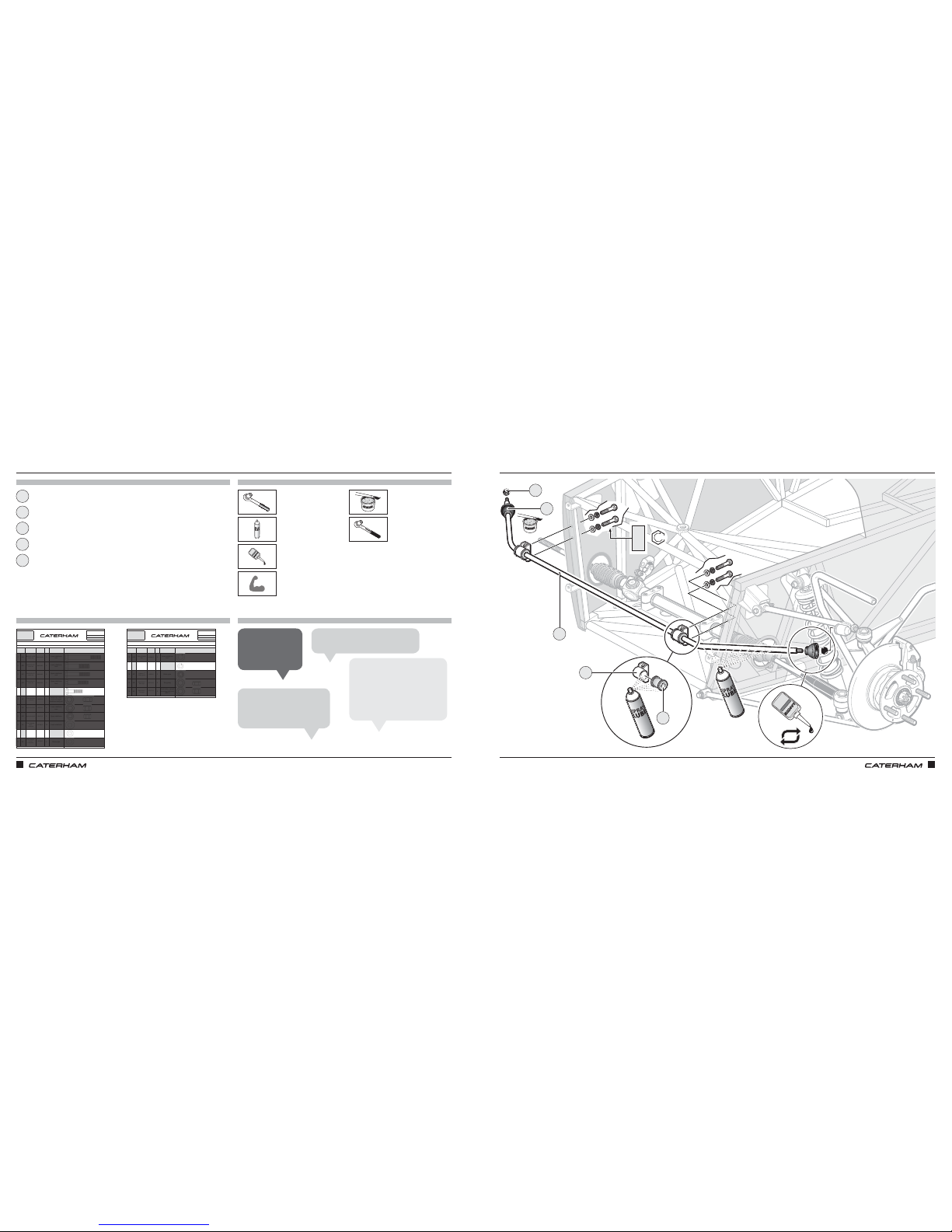
LAST PART OF THE FRONT SUSPENSION: CONNECTING THE TWO SIDES TOGETHERLAST PART OF THE FRONT SUSPENSION: CONNECTING THE TWO SIDES TOGETHER
PARTS
FIXINGS
TOOLS
TIPS
x4
x4
13mm
Anti-roll bar
Anti-roll bar rubber
Anti-roll bar bracket
Anti-roll bar dust cover
Anti-roll bar ball
x4
LOCTITE
LOCTITE
1
3
2
5
4
Getting the assembled anti‑roll
bar fully into both cups on the
upper wishbone can be a bit of a
fight. It’s made of springy stuff,
so don’t worry that you are
bending it.
Jamie A
Use four small cable
ties to secure the
dust cover.
Mick F
Grease the balls and cups generously.
Matt T
Check that the colour of the
mounting rubbers matches the
colour spot on the bar.
John K
1
2
3
4
5
AE
AK
AN
20Nm
LOCTITE
LOCTITE
REPEAT
Page 15
ASSEMBLY GUIDE ASSEMBLY GUIDE
20 21
PART
NUMBER
QTYUSED ON
1AA
BM12X100
2
Lower wishbone
rear
2AB
BM12X65
2
Lower wishbone
front
3AC
BM10X65
2
Upper wishbone
rear
4AD
BM10X60
2
Upper wishbone
front
5AE
BM8X40
4
Anti-roll bar
mounting brackets
6AF
NMPH14
1
Temporary use to
help lock upper
wishbone ball joint
7AG
NMYF12
2
Lower wishbone
rear
8AH
NMYF10
4
Upper wishbone
9AJ
WPCM12
18
Lower wishbone
10 AK
WPHM8
4
Anti-roll bar
mounting brackets
11 AL
WPH3/8
2
Brake pipe
Drawings are for illustrative purposes only and are not to scale.
A
SERIAL
NUMBER
44
Pack
PACK NUMBER
30F015B
FRONT SUSPENSION DeDION CARS (METRIC)
This pack may include extra fasteners to cover different options
ITEM
BASIC
DESCRIPTION
ILLUSTRATION
Bolt M12 x 100
Grade 10.9
Bolt M12 x 65
Grade 10.9
Bolt M10 x 65
Grade 10.9
Bolt M10 x 60
Grade 10.9
Bolt M8 x 40
Grade 10.9
Plain Nut M14
x 1.5 thread
Nyloc Nut M12
Plain Washer
⅜" x ¾"
Heavy duty
Page 1 of 2
Nyloc Nut M10
Plain Washer
M12
Chamfered
Plain Washer
M8
Heavy duty
94
PART
NUMBER
QTYUSED ON
12 AM
WSHM12
2
Lower wishbone
front
13 AN
WSHM8
6
Anti-roll bar
mounting brackets &
upper damper
mount
14 AP
WSS3/8
2 Brake pipe
15 AR
NFYH1/2
2Wing stay
16 AS
NFYF1/2
2
Front brake, upright
mounting (std track
ONLY)
Drawings are for illustrative purposes only and are not to scale.
A
SERIAL
NUMBER
44
Pack
PACK NUMBER
30F015B
FRONT SUSPENSION DeDION CARS (METRIC)
This pack may include extra fasteners to cover different options
ITEM
BASIC
DESCRIPTION
ILLUSTRATION
Spring Washer
M12
Nyloc Nut ½"
Full height
Page 2 of 2
Spring Washer
M8
Washer ⅜"
Shake-proof
Nyloc Nut ½"
Half height
PARTS
FIXINGS
TOOLS
TIPS
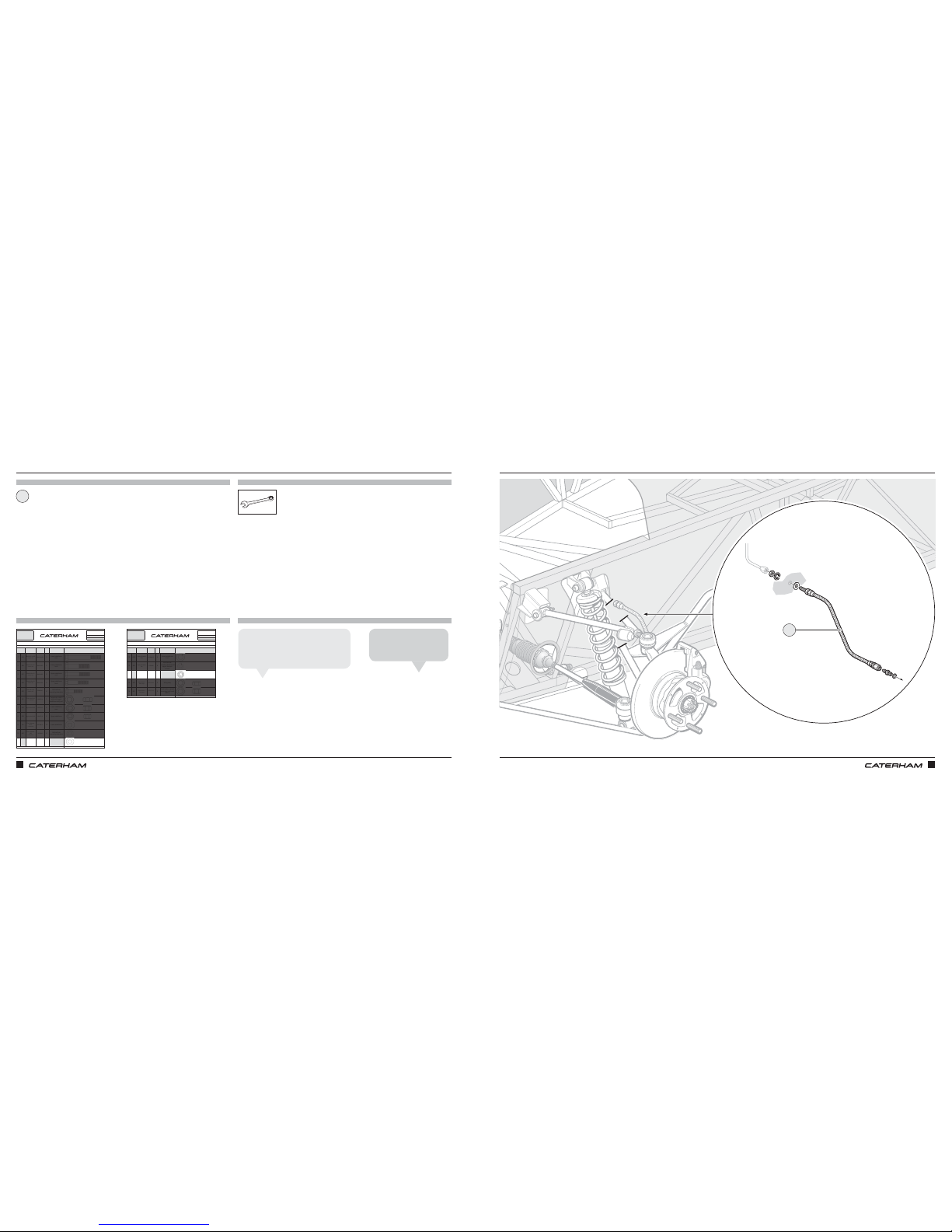
Brake hose
1
FITTING THE BRAKE HOSES FITTING THE BRAKE HOSES
13mm (x2)
⁄"
The hose will want to curve once fitted.
Make sure the curve points towards
the front of the car.
Khalfani D
Brake hoses come in
packs of 3: 2 front, 1 back.
Anthony L
1
x2
x2
Page 16
ASSEMBLY GUIDE ASSEMBLY GUIDE
22 23
PARTS
FIXINGS
TOOLS
TIPS
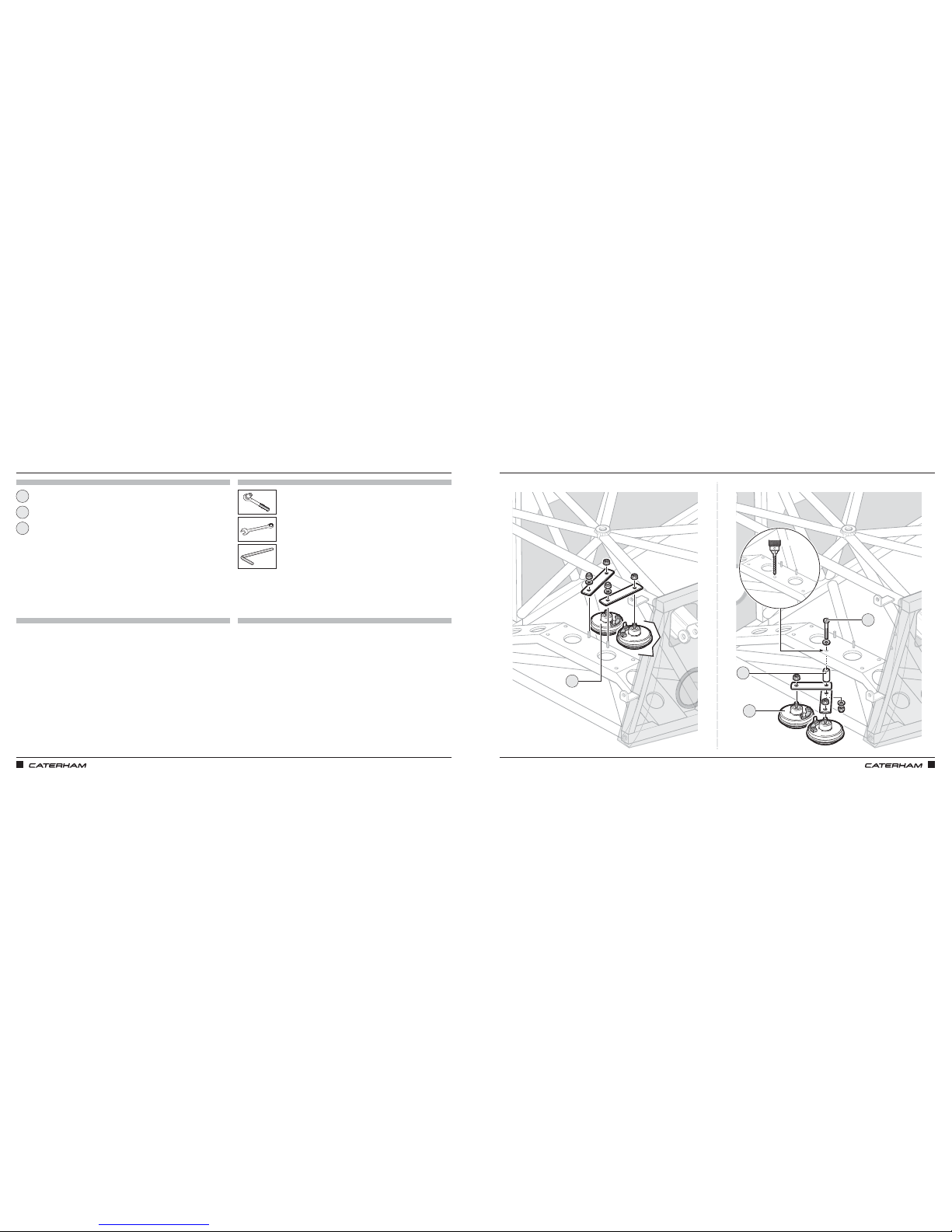
10mm
Horn kit (x2)
Bolt for spacer
Spacer (miscellaneous box)
13mm
6mm
1
3
2
LET'S MAKE SOME NOISE
1 x 8mm
LET'S MAKE SOME NOISE
Miscellaneous box
270/310/360 420
1
3
1
1 x 8mm
2
Page 17
ASSEMBLY GUIDE ASSEMBLY GUIDE
24 25
PARTS
FIXINGS
TOOLS
TIPS
PART
NUMBER
QTYUSED ON
1DA
BM8X50 1
Expansion tank
bracket to chassis
2DB
SF1/4X3/4
1
Expansion tank to
bracket
3DC
SM6X20
4 SV radiator bracket
4DD
30Z1072A
4Fan brackets to fan
5DE
SPHM6X16
4
Fan to radiator
cowling - SV only
6DF
NMYF6
8
x4 Fan to radiator
x4 SV radiator
bracket
7DG
NMPF8
8
Radiator bobbin
8DH
NFYF1/4
1
Expansion tank
bracket
9DI
WPH1/4
13
8 x SV rad bracket
4 x Fan fixings
1 x Expansion tank
braket
10 DJ
WPH5/16
4
Radiator bobbin
back
11 DK
WPH5/17X7/8
4
Radiator bobbin
front
Drawings are for illustrative purposes only and are not to scale.Page 1 of 2
Bolt M8 X 50
Grade 8.8
Plain Washer
5/16
"
Heavy duty
Nyloc Nut 1/4"
Plain Washer
1/4"
Heavy duty
Plain Washer
5/16" X 7/8"
Heavy duty
Setscrew M6X16
Panhead Pozi
Nyloc Nut M6
Plain Nut M8
Setscrew M8X20
Grade 8.8
COOLING SIGMA
This pack may include extra fasteners to cover different options
ITEM
BASIC
DESCRIPTION
ILLUSTRATION
Bolt M6 X 16 with
square section
Setscrew 1/4"
X 3/4"
D
SERIAL
NUMBER
44
Pack
PACK NUMBER
30C047B
PART
NUMBER
QTYUSED ON
12 DL
WPH1/4X7/8
1
Expansion tank
bracket
13 DM
WSH5/17
9
8 x Radiator bobbin
1 x Expansion tank
14 DN
SGT25-40
6
2 x U shape hose to
water rail
2 x Top radiator hose
2 x Bottom radiator hose
15 DO
SGT23-35
2
1 x Engine outlet to
big T piece
1 x Engine outlet to
heater inlet
16 DP
SGT16-25
18
6 x Heater inlet/outlet
3 x Big T-piece
1 x Expansion tank
2 x Modine
4 x Dry Sump
2 x Submarine
17 DQ
SGT8-16
6
Expansion tank
small T-piece
18 DR
1610-01015
12
Cowling flap
Drawings are for illustrative purposes only and are not to scale.Page 1 of 2
Plain Washer
1/4
" X 7/8"
Heavy duty
Page 1 of 2
Rivet - Black
5/32" X 0.47"
Hose Clip
17 - 25mm
Hose Clip
8 - 16mm
Hose Clip
30 - 40mm
Hose Clip
23 - 35mm
COOLING SIGMA
This pack may include extra fasteners to cover different options
ITEM
BASIC
DESCRIPTION
ILLUSTRATION
Spring Washer
5/16"
Heavy duty
D
SERIAL
NUMBER
44
Pack
PACK NUMBER
30C047B
x4
x4
x8
x4
x4
x4
13mm
10mm
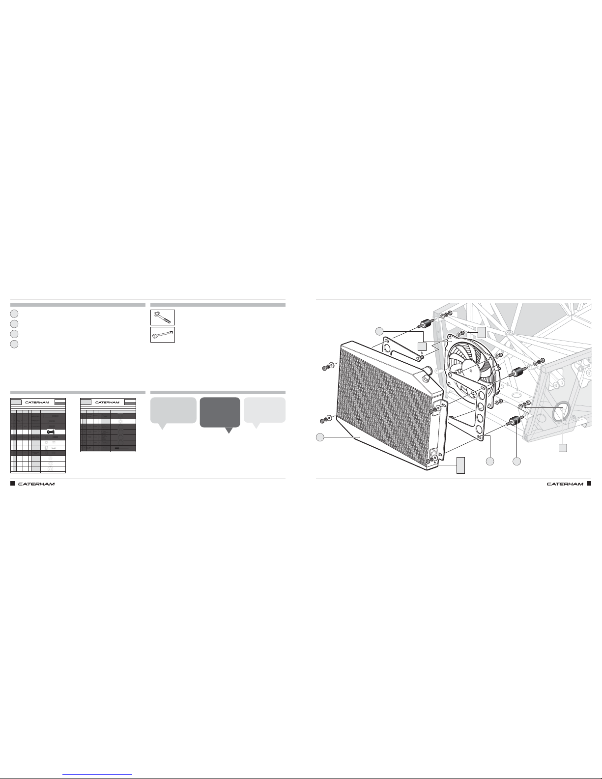
Radiator
Fan
Fan brackets (x2)
Radiator bobbins (x4)
13mm
x8
1
3
2
4
FITTING THE RADIATOR ON THE STANDARD CHASSIS FITTING THE RADIATOR ON THE STANDARD CHASSIS
The fan may have four
plastic legs or feet
that slot into it.
Vincent M
DD
42
1
DJ
3
DF
DI
DG
DM
DK
270/310/360
STANDARD CHASSIS
The fan may have a
'flat' section on the
rim. This should be
at the top.
James S
Be careful to tighten
the fan on gently
and just with a nip.
Lloyd D
Page 18
26 27
PART
NUMBER
QTYUSED ON
1DA
BM8X50 1
Expansion tank
bracket to chassis
2DB
SF1/4X3/4
1
Expansion tank to
bracket
3DC
SM6X20
4 SV radiator bracket
4DD
30Z1072A
4Fan brackets to fan
5DE
SPHM6X16
4
Fan to radiator
cowling - SV only
6DF
NMYF6
8
x4 Fan to radiator
x4 SV radiator
bracket
7DG
NMPF8
8
Radiator bobbin
8DH
NFYF1/4
1
Expansion tank
bracket
9DI
WPH1/4
13
8 x SV rad bracket
4 x Fan fixings
1 x Expansion tank
braket
10 DJ
WPH5/16
4
Radiator bobbin
back
11 DK
WPH5/17X7/8
4
Radiator bobbin
front
Drawings are for illustrative purposes only and are not to scale.Page 1 of 2
Bolt M8 X 50
Grade 8.8
Plain Washer
5/16
"
Heavy duty
Nyloc Nut 1/4"
Plain Washer
1/4"
Heavy duty
Plain Washer
5/16" X 7/8"
Heavy duty
Setscrew M6X16
Panhead Pozi
Nyloc Nut M6
Plain Nut M8
Setscrew M8X20
Grade 8.8
COOLING SIGMA
This pack may include extra fasteners to cover different options
ITEM
BASIC
DESCRIPTION
ILLUSTRATION
Bolt M6 X 16 with
square section
Setscrew 1/4"
X 3/4"
D
SERIAL
NUMBER
44
Pack
PACK NUMBER
30C047B
PART
NUMBER
QTYUSED ON
12 DL
WPH1/4X7/8
1
Expansion tank
bracket
13 DM
WSH5/17
9
8 x Radiator bobbin
1 x Expansion tank
14 DN
SGT25-40
6
2 x U shape hose to
water rail
2 x Top radiator hose
2 x Bottom radiator hose
15 DO
SGT23-35
2
1 x Engine outlet to
big T piece
1 x Engine outlet to
heater inlet
16 DP
SGT16-25
18
6 x Heater inlet/outlet
3 x Big T-piece
1 x Expansion tank
2 x Modine
4 x Dry Sump
2 x Submarine
17 DQ
SGT8-16
6
Expansion tank
small T-piece
18 DR
1610-01015
12
Cowling flap
Drawings are for illustrative purposes only and are not to scale.Page 1 of 2
Plain Washer
1/4
" X 7/8"
Heavy duty
Page 1 of 2
Rivet - Black
5/32" X 0.47"
Hose Clip
17 - 25mm
Hose Clip
8 - 16mm
Hose Clip
30 - 40mm
Hose Clip
23 - 35mm
COOLING SIGMA
This pack may include extra fasteners to cover different options
ITEM
BASIC
DESCRIPTION
ILLUSTRATION
Spring Washer
5/16"
Heavy duty
D
SERIAL
NUMBER
44
Pack
PACK NUMBER
30C047B
ASSEMBLY GUIDEASSEMBLY GUIDE
PARTS
FIXINGS
TOOLS
TIPS
x4
x4
x8
Brackets
1
3
2
5
4
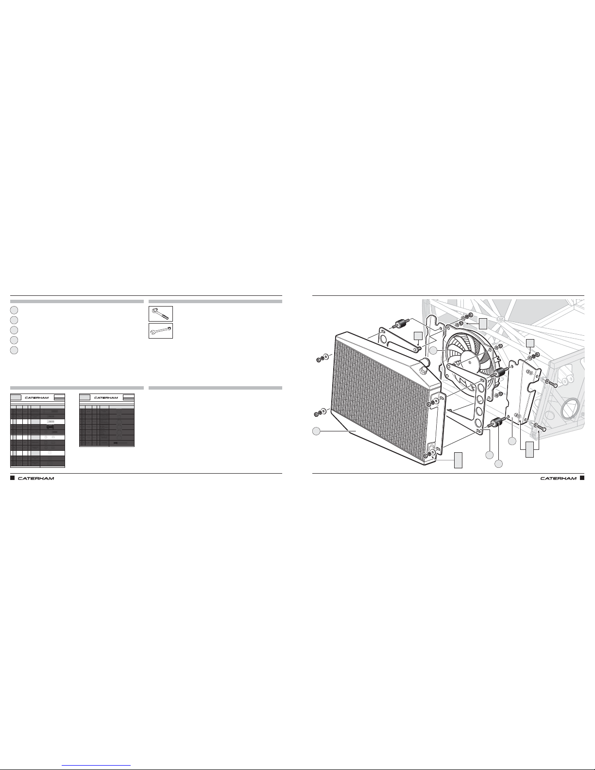
THE RADIATOR MOUNTING FOR THE WIDE-BODIED CHASSIS IS SLIGHTLY DIFFERENTTHE RADIATOR MOUNTING FOR THE WIDE-BODIED CHASSIS IS SLIGHTLY DIFFERENT
Radiator
Fan
Fan brackets (x2)
Radiator bobbins (x4)
13mm
10mm
10mm
13mm
270/310/360
WIDE CHASSIS
5
1
DG
DM
DK
DD
4
2
DF
DI
3
DJ
DC
DI
DF
Page 19
PART
NUMBER
QTYUSED ON
1DA
BM8X50 1
Expansion tank
bracket to chassis
2DB
SF1/4X3/4
1
Expansion tank to
bracket
3DC
SM6X20
4 SV radiator bracket
4DD
30Z1072A
4Fan brackets to fan
5DE
SPHM6X16
4
Fan to radiator
cowling - SV only
6DF
NMYF6
8
x4 Fan to radiator
x4 SV radiator
bracket
7DG
NMPF8
8
Radiator bobbin
8DH
NFYF1/4
1
Expansion tank
bracket
9DI
WPH1/4
13
8 x SV rad bracket
4 x Fan fixings
1 x Expansion tank
braket
10 DJ
WPH5/16
4
Radiator bobbin
back
11 DK
WPH5/17X7/8
4
Radiator bobbin
front
Drawings are for illustrative purposes only and are not to scale.Page 1 of 2
Bolt M8 X 50
Grade 8.8
Plain Washer
5/16
"
Heavy duty
Nyloc Nut 1/4"
Plain Washer
1/4"
Heavy duty
Plain Washer
5/16" X 7/8"
Heavy duty
Setscrew M6X16
Panhead Pozi
Nyloc Nut M6
Plain Nut M8
Setscrew M8X20
Grade 8.8
COOLING SIGMA
This pack may include extra fasteners to cover different options
ITEM
BASIC
DESCRIPTION
ILLUSTRATION
Bolt M6 X 16 with
square section
Setscrew 1/4"
X 3/4"
D
SERIAL
NUMBER
44
Pack
PACK NUMBER
30C047B
PART
NUMBER
QTYUSED ON
12 DL
WPH1/4X7/8
1
Expansion tank
bracket
13 DM
WSH5/17
9
8 x Radiator bobbin
1 x Expansion tank
14 DN
SGT25-40
6
2 x U shape hose to
water rail
2 x Top radiator hose
2 x Bottom radiator hose
15 DO
SGT23-35
2
1 x Engine outlet to
big T piece
1 x Engine outlet to
heater inlet
16 DP
SGT16-25
18
6 x Heater inlet/outlet
3 x Big T-piece
1 x Expansion tank
2 x Modine
4 x Dry Sump
2 x Submarine
17 DQ
SGT8-16
6
Expansion tank
small T-piece
18 DR
1610-01015
12
Cowling flap
Drawings are for illustrative purposes only and are not to scale.Page 1 of 2
Plain Washer
1/4
" X 7/8"
Heavy duty
Page 1 of 2
Rivet - Black
5/32" X 0.47"
Hose Clip
17 - 25mm
Hose Clip
8 - 16mm
Hose Clip
30 - 40mm
Hose Clip
23 - 35mm
COOLING SIGMA
This pack may include extra fasteners to cover different options
ITEM
BASIC
DESCRIPTION
ILLUSTRATION
Spring Washer
5/16"
Heavy duty
D
SERIAL
NUMBER
44
Pack
PACK NUMBER
30C047B
2928
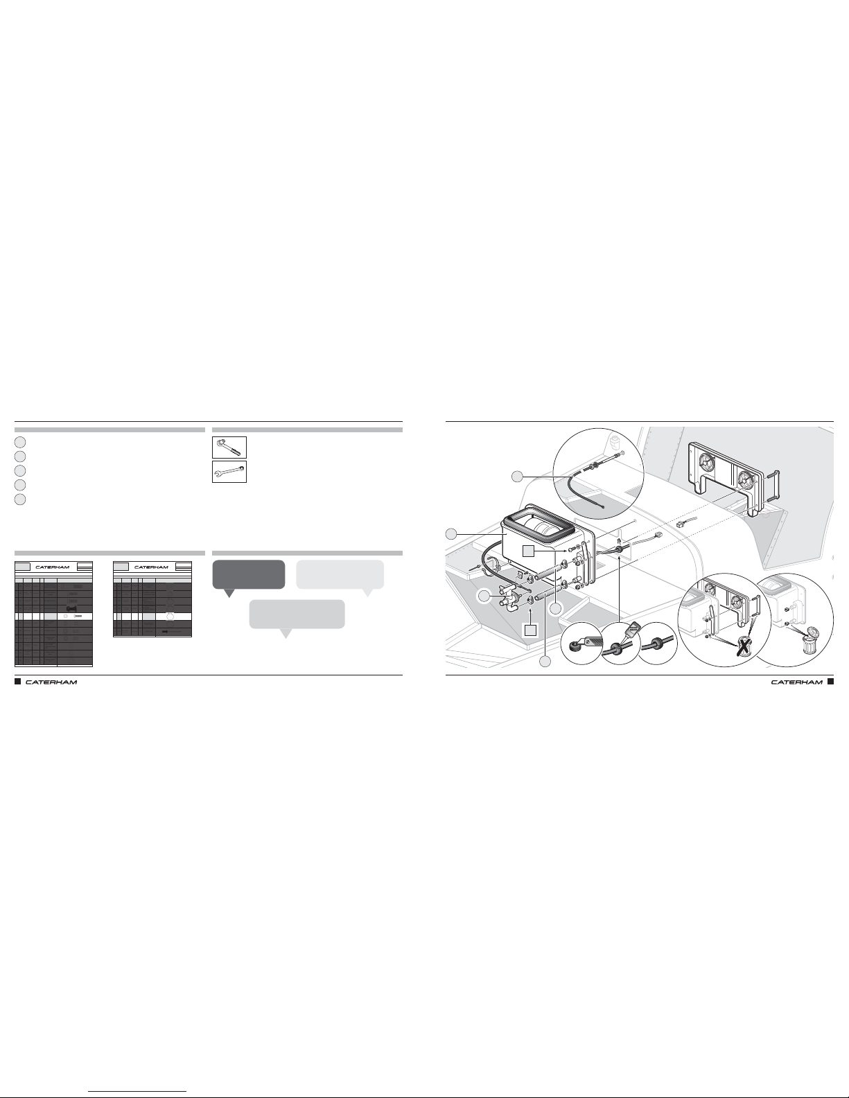
Lower hose 110mm (cut from long length)
4
PARTS
FIXINGS
TOOLS
TIPS
x2
10mm
7mm
19mm
Heater
Heater cable
Valve
Upper hose 120mm (cut from long length)
x4
1
3
2
5
THINGS ARE HEATING UP THINGS ARE HEATING UP
Remember to remove bungs
from heater.
Jamie A
It’s worth re‑tightening after a couple
of uses of car.
John S
3
1
DP
44
DE
2
Use 7mm for jubilee clips but not
too tight!
Chris B
5
ASSEMBLY GUIDEASSEMBLY GUIDE
Page 20
ASSEMBLY GUIDE ASSEMBLY GUIDE
30 31
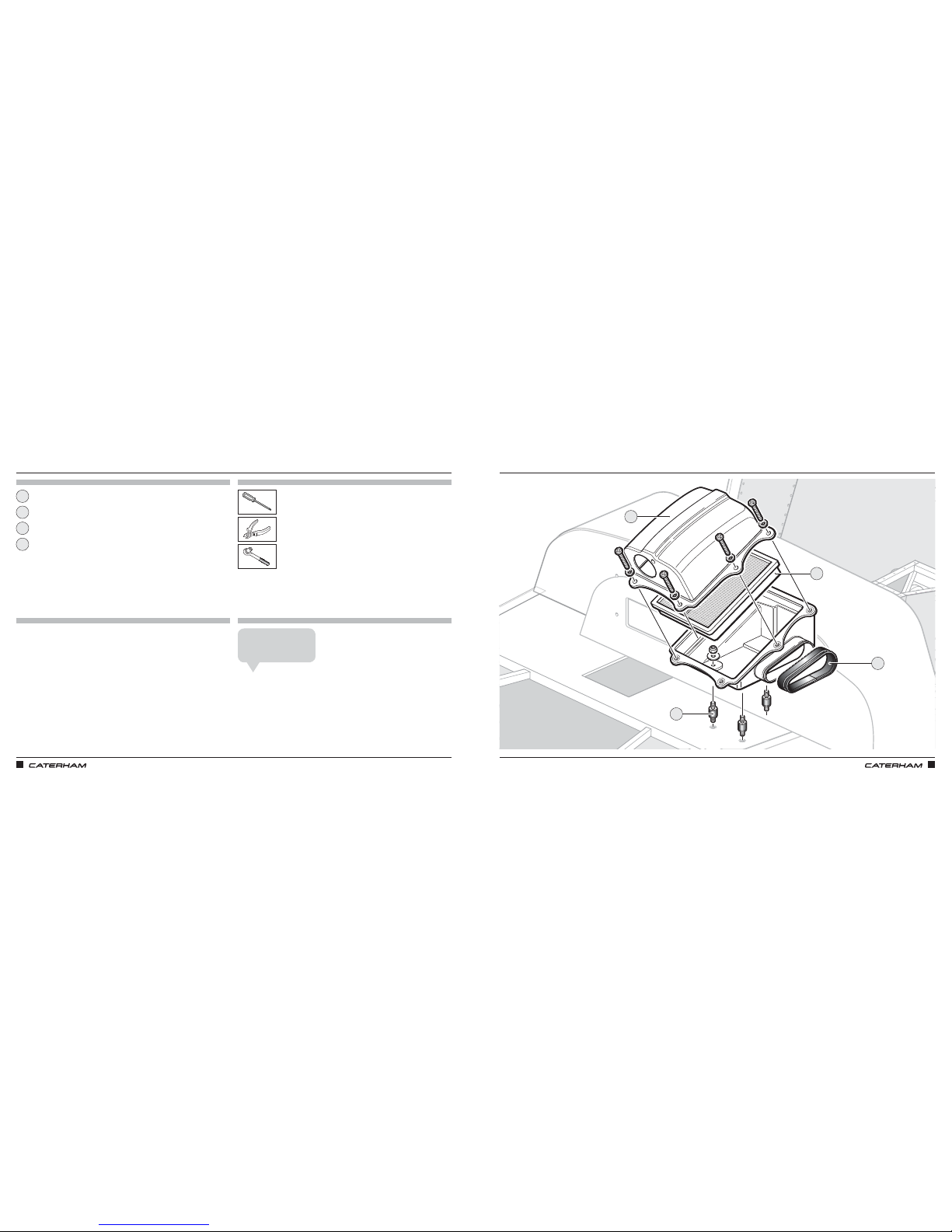
KEEPING THE AIR CLEANKEEPING THE AIR CLEAN
PARTS
FIXINGS
TOOLS
TIPS
Air box
Rubber mounts
Air filter
Trim
8mm
1
3
2
4
2
1
4
3
Bobbins are screwed into
the car by hand.
John K
Unmarked bag:
• M5 (x6)
• Spring (x6)
• Flats (x6)
• Nylocs M5 (x3)
• ⁄ washers (x3)
• ¾ washers (x3)
• Screws (x20)
Page 21
ASSEMBLY GUIDE ASSEMBLY GUIDE
32 33
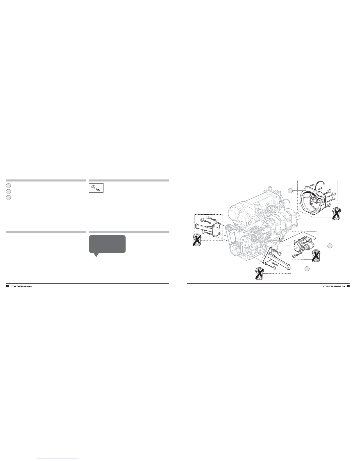
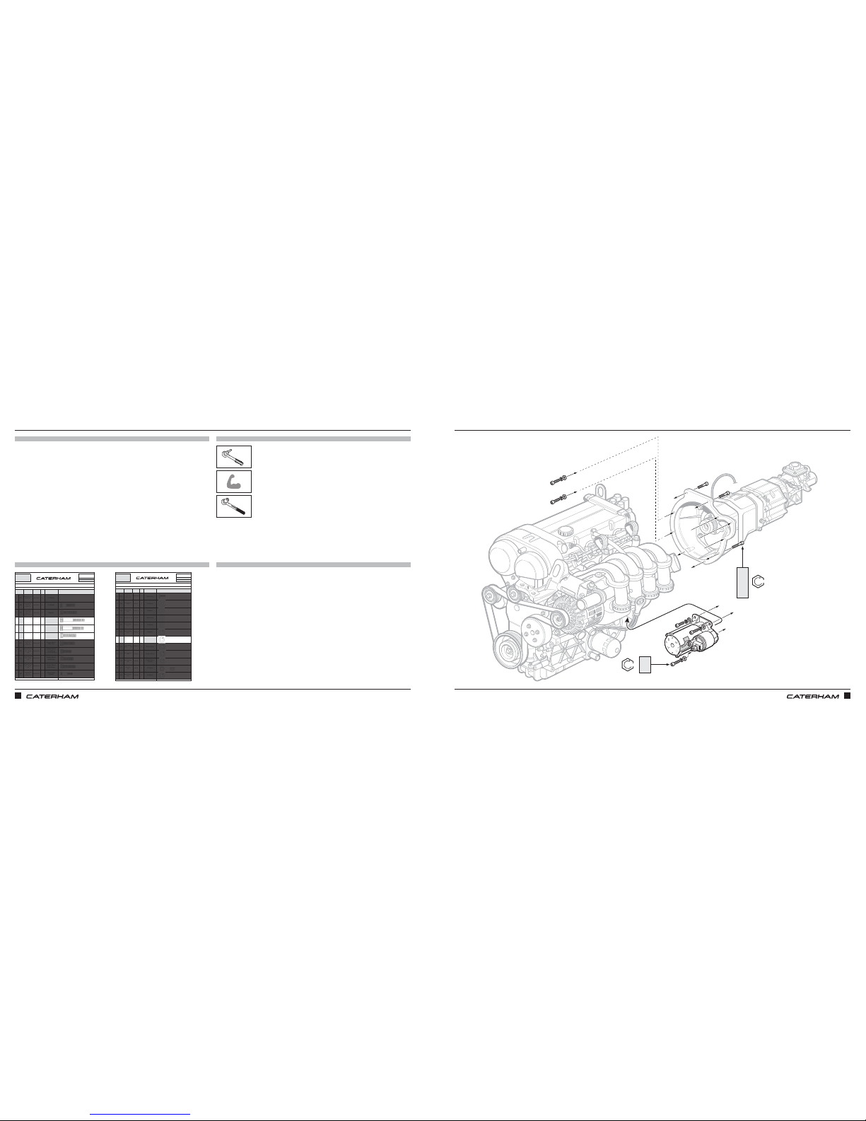
GETTING READY TO PUT THE ENGINE INGETTING READY TO PUT THE ENGINE IN
PARTS
FIXINGS
TOOLS
TIPS
6mm
8mm
Engine mount
Bellhousing
Starter motor
1
3
2
You will need to remove the engine
mounts and starter motor but
don’t throw away the bolts – keep
them safe!
Chris N
3
2
1
Page 22
ASSEMBLY GUIDE ASSEMBLY GUIDE
34 35
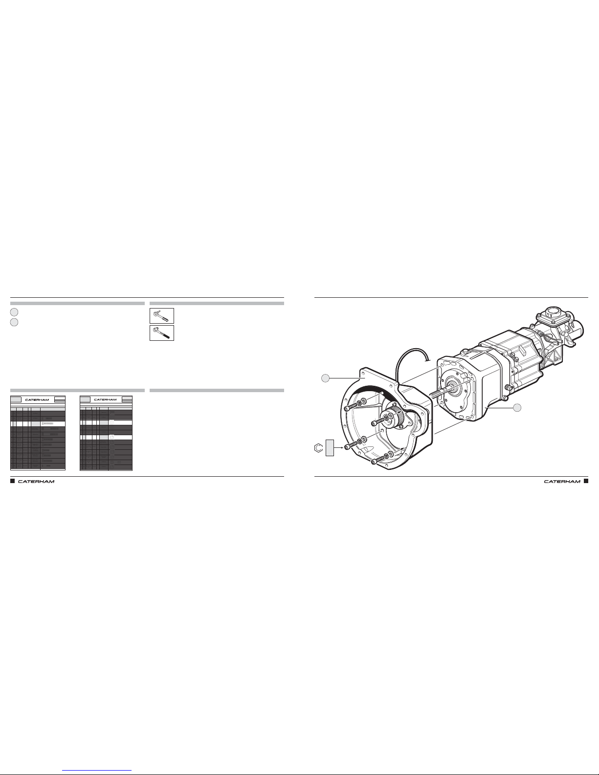
ATTACH THE GEARBOX TO THE BELLHOUSINGATTACH THE GEARBOX TO THE BELLHOUSING
PARTS
FIXINGS
TOOLS
TIPS
PART
NUMBER
QTYUSED ON
1EA
3EZ1137A 2
AV Mount
2EB
30Z1076A
4 AV Mount
3EC
3EZ1142A
4Gearbo x
4ED
BMCH10X60
4
1 x Bellhousing
3 x Starter Motor
5EE
BMCH10X55
3Bellhousing
6EF
BMCH10X40
3Bellhousing
7EG
BMCH10X35
2
Engine Mount
RHS Top
8EH
BMCH8X25
2
Engine Mount
1 x LHS Top
1 x LHS Bottom
9EI
BMCH8X30
1
Engine Mount
LHS Bottom
10 EJ
BMCH8X35
2
Engine Mount
RHS Bottom
11 EK
BMCH6X25
3
ClutchSlave
Cylinder
Drawings are for illustrative purposes only and are not to scale.
E
SERIAL
NUMBER
66
Pack
PACK NUMBER
3EZ1105F
SIGMA GEARBOX 5 SPEED
This pack may include extra fasteners to cover different options
ITEM
BASIC
DESCRIPTION
ILLUSTRATION
Bolt M14 X 40
Grade 12.9
Caphead Bolt
M8 X 40
Grade 12.9
Caphead Bolt
M12 X 50
Grade 12.9
Coarse Thread
Caphead Bolt
M10 X 60
Grade 12.9
Caphead Bolt
M10 X 55
Grade 12.9
Caphead Bolt
M10 X 40
Grade 12.9
Caphead Bolt
M10 X 35
Grade 12.9
Caphead Bolt
M6 X 25
Grade 12.9
Page 1 of 2
Caphead Bolt M8
X 25 Grade
12.9
Caphead Bolt M8
X 30 Grade
12.9
Caphead Bolt M8
X 35 Grade
12.9
PART
NUMBER
QTYUSED ON
12 EL
3GZ1163A 3
Gear Lever
13 EM
WPH14
2 AV Mount
14 EN
30Z2031A
4Gearbox
15 EO
WPHM6
3Gear Lever
16 EP
WPH5/16
8 AV Mount
17 EQ
WSHM12
4Gearbox
18 ER
WSHM10
10
x 7 Bellhousing x
3 Engine Mount
19 ES
WSHM10
3
Starter Motor
20 ET
WSHM8
5
Engine Mount
21 EU
WSHM6
3
Clutch Slave
Cylinder
22 EV
NMYF8
4
AV Mount
23 EW
30Z2030A
2
AV Mount
Drawings are for illustrative purposes only and are not to scale.
E
SERIAL
NUMBER
66
Pack
PACK NUMBER
3EZ1105F
SIGMA GEARBOX 5 SPEED
This pack may include extra fasteners to cover different options
ITEM
BASIC
DESCRIPTION
ILLUSTRATION
Buttonhead Bolt
M6 X 10
Grade 10.9
Internal Hex
Plain Washer
M12
Spring Washer
M10
Wire Spring
Washer M10
Plain Washer
M14
Plain Washer M6
Plain Washer
5/16"
Spring Washer
M14
Page 2 of 2
Spring Washer
M12
Spring Washer
M8
Spring Washer
M6
Myloc Nut
M8
x4
10mm
Gearbox
Bell housing
x4
x4
1
2
EC
EN
EQ
2
1
68Nm
Page 23
ASSEMBLY GUIDE
36 37
PART
NUMBER
QTYUSED ON
1EA
3EZ1137A 2
AV Mount
2EB
30Z1076A
4 AV Mount
3EC
3EZ1142A
4Gearbo x
4ED
BMCH10X60
4
1 x Bellhousing
3 x Starter Motor
5EE
BMCH10X55
3Bellhousing
6EF
BMCH10X40
3Bellhousing
7EG
BMCH10X35
2
Engine Mount
RHS Top
8EH
BMCH8X25
2
Engine Mount
1 x LHS Top
1 x LHS Bottom
9EI
BMCH8X30
1
Engine Mount
LHS Bottom
10 EJ
BMCH8X35
2
Engine Mount
RHS Bottom
11 EK
BMCH6X25
3
ClutchSlave
Cylinder
Drawings are for illustrative purposes only and are not to scale.
E
SERIAL
NUMBER
66
Pack
PACK NUMBER
3EZ1105F
SIGMA GEARBOX 5 SPEED
This pack may include extra fasteners to cover different options
ITEM
BASIC
DESCRIPTION
ILLUSTRATION
Bolt M14 X 40
Grade 12.9
Caphead Bolt
M8 X 40
Grade 12.9
Caphead Bolt
M12 X 50
Grade 12.9
Coarse Thread
Caphead Bolt
M10 X 60
Grade 12.9
Caphead Bolt
M10 X 55
Grade 12.9
Caphead Bolt
M10 X 40
Grade 12.9
Caphead Bolt
M10 X 35
Grade 12.9
Caphead Bolt
M6 X 25
Grade 12.9
Page 1 of 2
Caphead Bolt M8
X 25 Grade
12.9
Caphead Bolt M8
X 30 Grade
12.9
Caphead Bolt M8
X 35 Grade
12.9
PART
NUMBER
QTYUSED ON
12 EL
3GZ1163A 3
Gear Lever
13 EM
WPH14
2 AV Mount
14 EN
30Z2031A
4Gearbox
15 EO
WPHM6
3Gear Lever
16 EP
WPH5/16
8 AV Mount
17 EQ
WSHM12
4Gearbox
18 ER
WSHM10
10
x 7 Bellhousing x
3 Engine Mount
19 ES
WSHM10
3
Starter Motor
20 ET
WSHM8
5
Engine Mount
21 EU
WSHM6
3
Clutch Slave
Cylinder
22 EV
NMYF8
4
AV Mount
23 EW
30Z2030A
2
AV Mount
Drawings are for illustrative purposes only and are not to scale.
E
SERIAL
NUMBER
66
Pack
PACK NUMBER
3EZ1105F
SIGMA GEARBOX 5 SPEED
This pack may include extra fasteners to cover different options
ITEM
BASIC
DESCRIPTION
ILLUSTRATION
Buttonhead Bolt
M6 X 10
Grade 10.9
Internal Hex
Plain Washer
M12
Spring Washer
M10
Wire Spring
Washer M10
Plain Washer
M14
Plain Washer M6
Plain Washer
5/16"
Spring Washer
M14
Page 2 of 2
Spring Washer
M12
Spring Washer
M8
Spring Washer
M6
Myloc Nut
M8
ASSEMBLY GUIDE
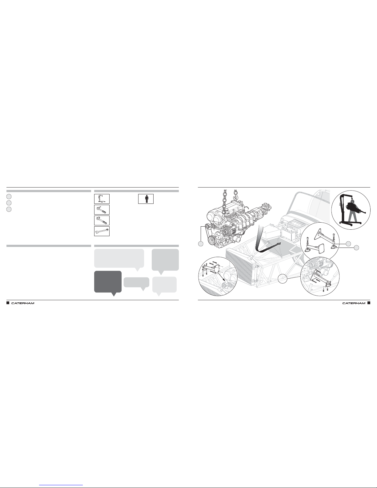
AND THEN THE GEARBOX TO THE ENGINEAND THEN THE GEARBOX TO THE ENGINE
PARTS
FIXINGS
TOOLS
TIPS
x1
x3
x3
8mm
x7
ED
ES
ED
EE
EF
ER
54Nm
54Nm
Page 24
38 39
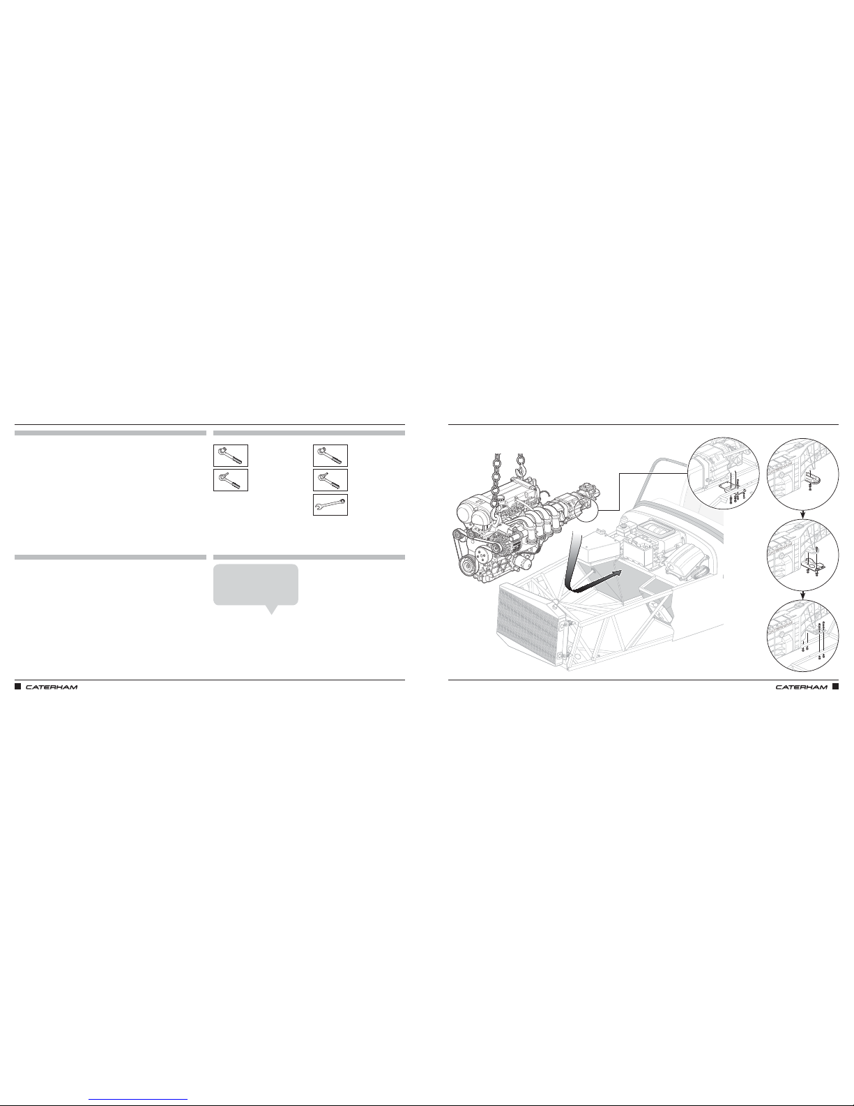
AT LAST, THE ENGINE IS GOING INAT LAST, THE ENGINE IS GOING IN
PARTS
FIXINGS
TOOLS
TIPS
Engine mounts
Engine rubbers
6mm
8mm
⅜”
13mm
13mm
15mm
1
2
Protect the chassis
with soft stuff such
as cardboard or folded
towels/blankets. Just
not your fingers.
Tiago O
It's 54Nm for the
bolts tightened with
the 8mm hex socket
& 30Nm for the 6mm
hex socket.
Grant P
It will fit – keep at it!
Rich T
Removing the
tensioner will make
things much easier.
James A
When fitting the engine rubbers and mounts,
do them as loosely as possible so you can
wiggle things to get bolts in. Tighten it all up
gradually once all the bolts are in.
Jamie A
1
2
+
Tensioner
3
3
ASSEMBLY GUIDE ASSEMBLY GUIDE
Page 25
ASSEMBLY GUIDE ASSEMBLY GUIDE
40 41
AND THE GEARBOX IS FIXED IN PLACE
PARTS
FIXINGS
TOOLS
TIPS
AND THE GEARBOX IS FIXED IN PLACE
6 SPEED5 SPEED
Once the engine is in, the
wiring can be connected to the
car's loom. It should be self
explanatory.
Chris B
6mm 6mm
13mm
22mm
13mm
19mm
13mm
5 Speed 6 Speed
Page 26
ASSEMBLY GUIDE ASSEMBLY GUIDE
42 43
PARTS
FIXINGS
TOOLS
TIPS
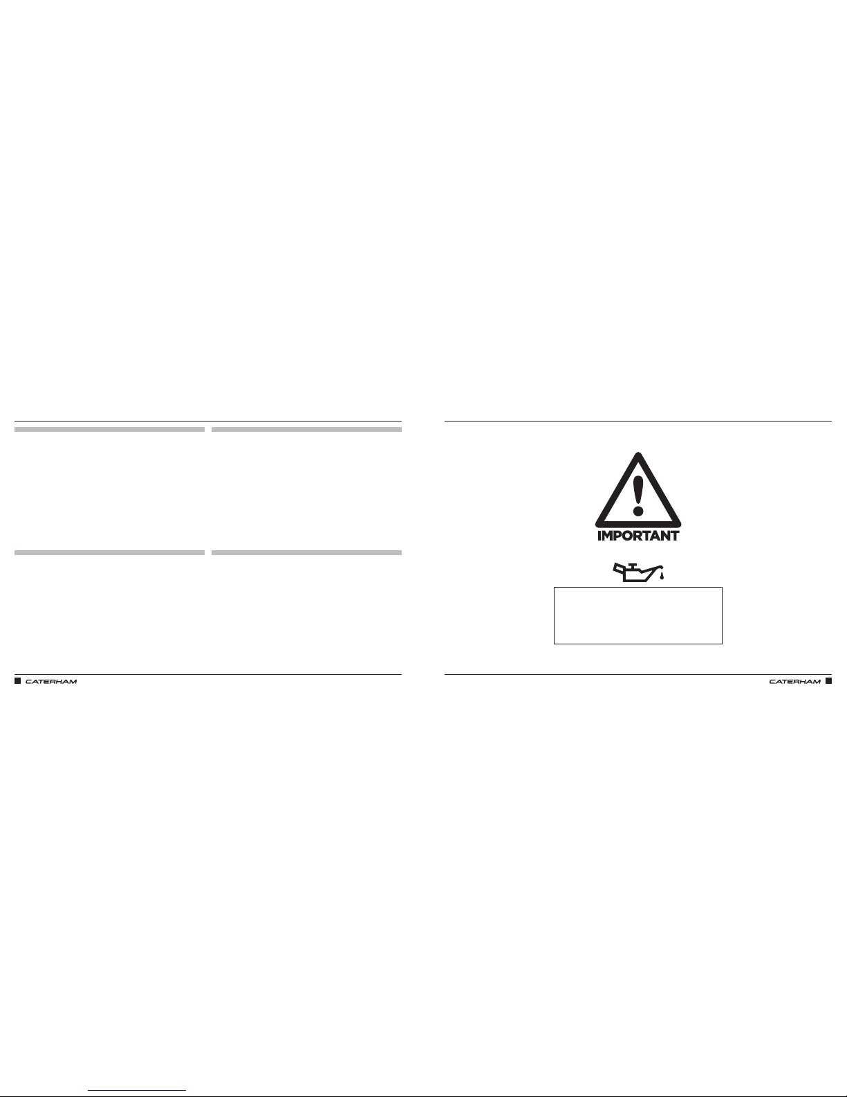
Engine oil SW-30
Gear oil GL4
FILLING THE ENGINE AND GEARBOX WITH OILFILLING THE ENGINE AND GEARBOX WITH OIL
Ford 1.6L Engine = 3.8 Litres
5 Speed Gearbox = (Pre-Filled)
6 Speed Gearbox = Fill to level of filling point
on the side of gearbox
Page 27
ASSEMBLY GUIDE ASSEMBLY GUIDE
44 45
PART
NUMBER
QTYUSED ON
1DA
BM8X50 1
Expansion tank
bracket to chassis
2DB
SF1/4X3/4
1
Expansion tank to
bracket
3DC
SM6X20
4 SV radiator bracket
4DD
30Z1072A
4Fan brackets to fan
5DE
SPHM6X16
4
Fan to radiator
cowling - SV only
6DF
NMYF6
8
x4 Fan to radiator
x4 SV radiator
bracket
7DG
NMPF8
8
Radiator bobbin
8DH
NFYF1/4
1
Expansion tank
bracket
9DI
WPH1/4
13
8 x SV rad bracket
4 x Fan fixings
1 x Expansion tank
braket
10 DJ
WPH5/16
4
Radiator bobbin
back
11 DK
WPH5/17X7/8
4
Radiator bobbin
front
Drawings are for illustrative purposes only and are not to scale.Page 1 of 2
Bolt M8 X 50
Grade 8.8
Plain Washer
5/16
"
Heavy duty
Nyloc Nut 1/4"
Plain Washer
1/4"
Heavy duty
Plain Washer
5/16" X 7/8"
Heavy duty
Setscrew M6X16
Panhead Pozi
Nyloc Nut M6
Plain Nut M8
Setscrew M8X20
Grade 8.8
COOLING SIGMA
This pack may include extra fasteners to cover different options
ITEM
BASIC
DESCRIPTION
ILLUSTRATION
Bolt M6 X 16 with
square section
Setscrew 1/4"
X 3/4"
D
SERIAL
NUMBER
44
Pack
PACK NUMBER
30C047B
PART
NUMBER
QTYUSED ON
12 DL
WPH1/4X7/8
1
Expansion tank
bracket
13 DM
WSH5/17
9
8 x Radiator bobbin
1 x Expansion tank
14 DN
SGT25-40
6
2 x U shape hose to
water rail
2 x Top radiator hose
2 x Bottom radiator hose
15 DO
SGT23-35
2
1 x Engine outlet to
big T piece
1 x Engine outlet to
heater inlet
16 DP
SGT16-25
18
6 x Heater inlet/outlet
3 x Big T-piece
1 x Expansion tank
2 x Modine
4 x Dry Sump
2 x Submarine
17 DQ
SGT8-16
6
Expansion tank
small T-piece
18 DR
1610-01015
12
Cowling flap
Drawings are for illustrative purposes only and are not to scale.Page 1 of 2
Plain Washer
1/4
" X 7/8"
Heavy duty
Page 1 of 2
Rivet - Black
5/32" X 0.47"
Hose Clip
17 - 25mm
Hose Clip
8 - 16mm
Hose Clip
30 - 40mm
Hose Clip
23 - 35mm
COOLING SIGMA
This pack may include extra fasteners to cover different options
ITEM
BASIC
DESCRIPTION
ILLUSTRATION
Spring Washer
5/16"
Heavy duty
D
SERIAL
NUMBER
44
Pack
PACK NUMBER
30C047B
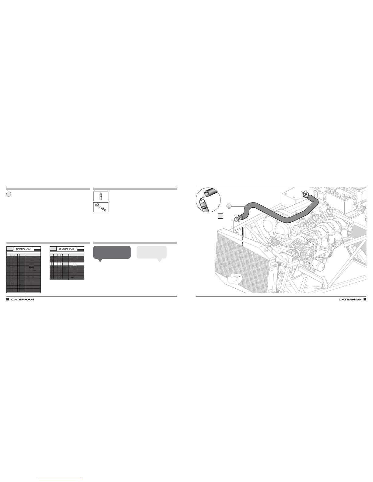
START PLUMBINGSTART PLUMBING
PARTS
FIXINGS
TOOLS
TIPS
Lower radiator hose
7mm
x2
1
DN
1
Reminder for later on: nip up the
clips once the car has been run.
Grant P
Fit the hose to the larger
outlet on the engine.
Mick F
Page 28
ASSEMBLY GUIDE ASSEMBLY GUIDE
46 47
PART
NUMBER
QTYUSED ON
1DA
BM8X50 1
Expansion tank
bracket to chassis
2DB
SF1/4X3/4
1
Expansion tank to
bracket
3DC
SM6X20
4 SV radiator bracket
4DD
30Z1072A
4Fan brackets to fan
5DE
SPHM6X16
4
Fan to radiator
cowling - SV only
6DF
NMYF6
8
x4 Fan to radiator
x4 SV radiator
bracket
7DG
NMPF8
8
Radiator bobbin
8DH
NFYF1/4
1
Expansion tank
bracket
9DI
WPH1/4
13
8 x SV rad bracket
4 x Fan fixings
1 x Expansion tank
braket
10 DJ
WPH5/16
4
Radiator bobbin
back
11 DK
WPH5/17X7/8
4
Radiator bobbin
front
Drawings are for illustrative purposes only and are not to scale.Page 1 of 2
Bolt M8 X 50
Grade 8.8
Plain Washer
5/16
"
Heavy duty
Nyloc Nut 1/4"
Plain Washer
1/4"
Heavy duty
Plain Washer
5/16" X 7/8"
Heavy duty
Setscrew M6X16
Panhead Pozi
Nyloc Nut M6
Plain Nut M8
Setscrew M8X20
Grade 8.8
COOLING SIGMA
This pack may include extra fasteners to cover different options
ITEM
BASIC
DESCRIPTION
ILLUSTRATION
Bolt M6 X 16 with
square section
Setscrew 1/4"
X 3/4"
D
SERIAL
NUMBER
44
Pack
PACK NUMBER
30C047B
PART
NUMBER
QTYUSED ON
12 DL
WPH1/4X7/8
1
Expansion tank
bracket
13 DM
WSH5/17
9
8 x Radiator bobbin
1 x Expansion tank
14 DN
SGT25-40
6
2 x U shape hose to
water rail
2 x Top radiator hose
2 x Bottom radiator hose
15 DO
SGT23-35
2
1 x Engine outlet to
big T piece
1 x Engine outlet to
heater inlet
16 DP
SGT16-25
18
6 x Heater inlet/outlet
3 x Big T-piece
1 x Expansion tank
2 x Modine
4 x Dry Sump
2 x Submarine
17 DQ
SGT8-16
6
Expansion tank
small T-piece
18 DR
1610-01015
12
Cowling flap
Drawings are for illustrative purposes only and are not to scale.Page 1 of 2
Plain Washer
1/4
" X 7/8"
Heavy duty
Page 1 of 2
Rivet - Black
5/32" X 0.47"
Hose Clip
17 - 25mm
Hose Clip
8 - 16mm
Hose Clip
30 - 40mm
Hose Clip
23 - 35mm
COOLING SIGMA
This pack may include extra fasteners to cover different options
ITEM
BASIC
DESCRIPTION
ILLUSTRATION
Spring Washer
5/16"
Heavy duty
D
SERIAL
NUMBER
44
Pack
PACK NUMBER
30C047B
PARTS
FIXINGS
TOOLS
TIPS
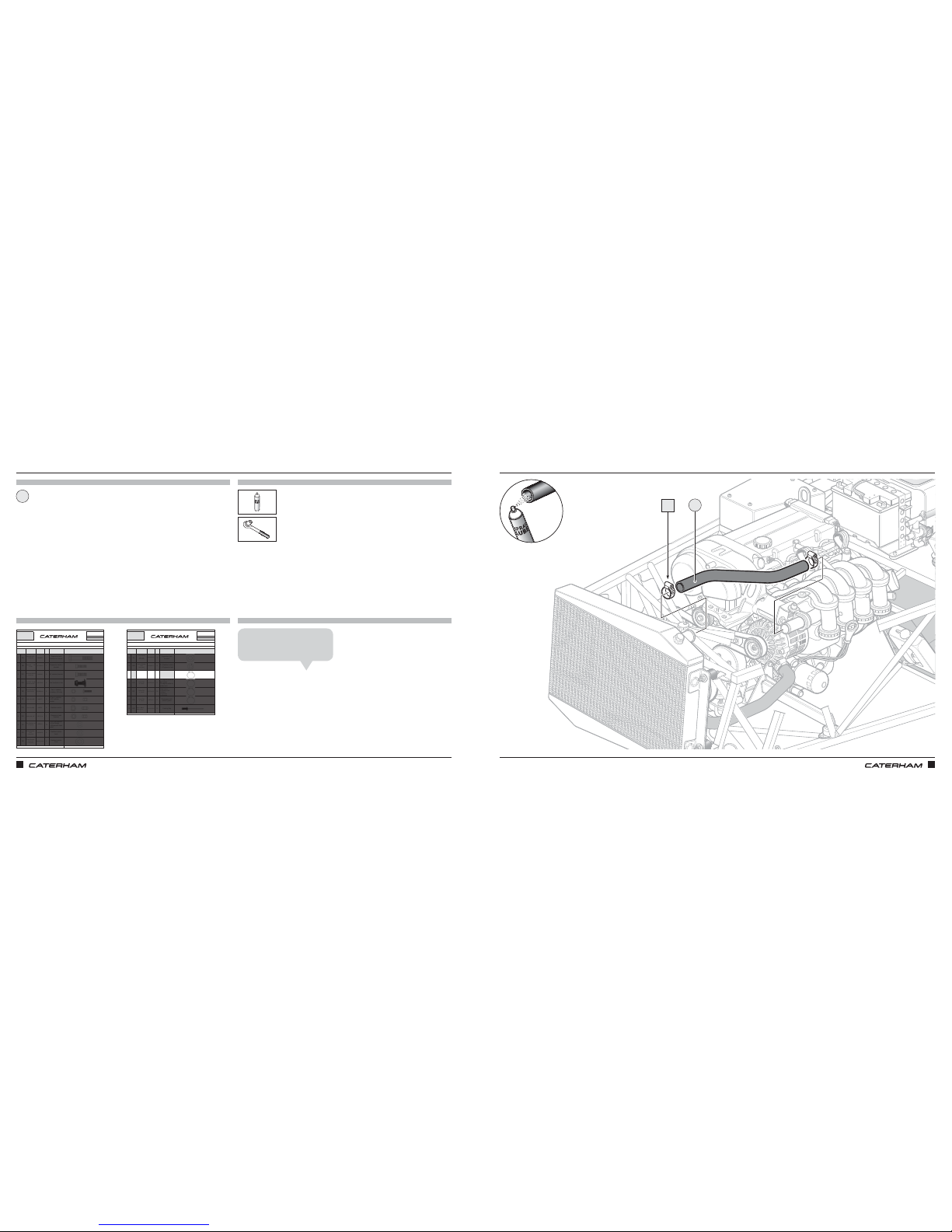
Upper radiator hose
1
x2
7mm
AND KEEP PLUMBINGAND KEEP PLUMBING
1
DN
Reminder for later on: nip up the
clips once the car has been run.
James A
Page 29

ASSEMBLY GUIDE ASSEMBLY GUIDE
48 49
Now is a good time to take some photos Have you applied for your IVA yet?
Page 30
ASSEMBLY GUIDE ASSEMBLY GUIDE
50 51
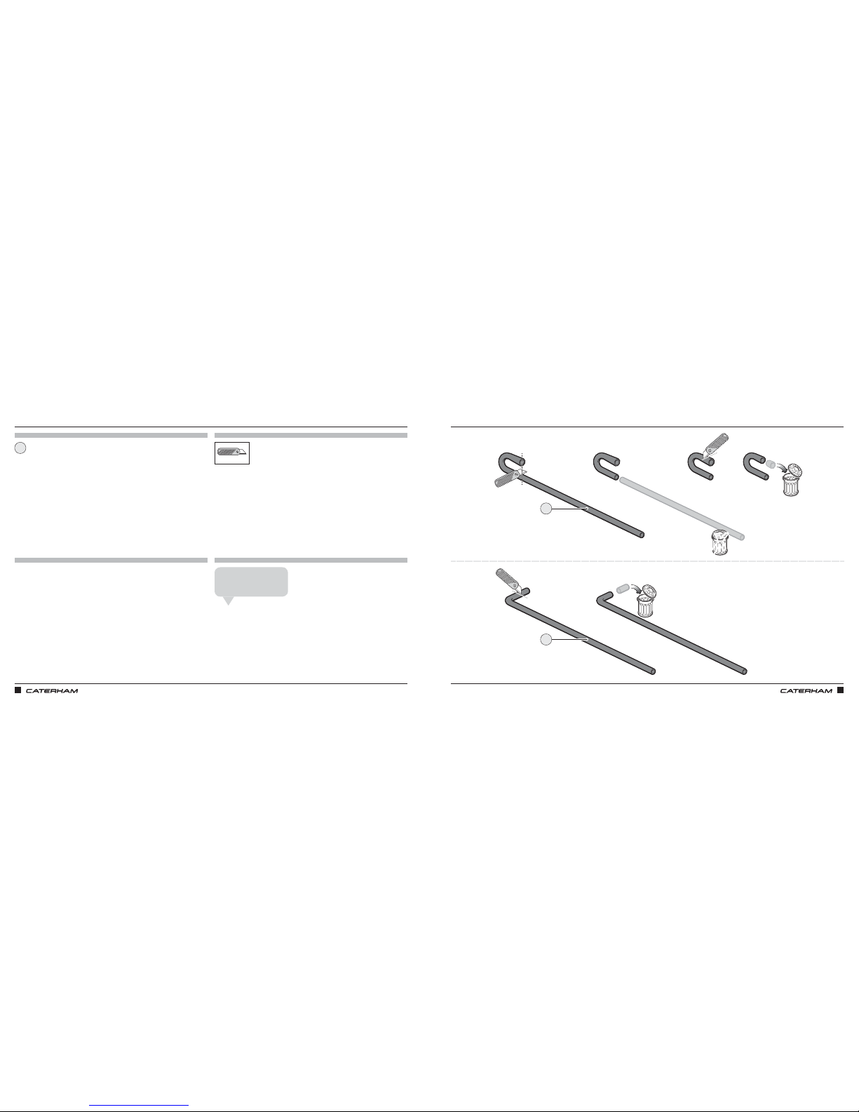
A BIT OF SUB-ASSEMBLY – SOME HOSES NEED MODIFYINGA BIT OF SUB-ASSEMBLY – SOME HOSES NEED MODIFYING
PARTS TOOLS
TIPS
Silicone hoses
1
Don't throw away the long
piece of hose after cutting.
Rich T
1
1
FIXINGS
Page 31
ASSEMBLY GUIDE ASSEMBLY GUIDE
52 53
PART
NUMBER
QTYUSED ON
1DA
BM8X50 1
Expansion tank
bracket to chassis
2DB
SF1/4X3/4
1
Expansion tank to
bracket
3DC
SM6X20
4 SV radiator bracket
4DD
30Z1072A
4Fan brackets to fan
5DE
SPHM6X16
4
Fan to radiator
cowling - SV only
6DF
NMYF6
8
x4 Fan to radiator
x4 SV radiator
bracket
7DG
NMPF8
8
Radiator bobbin
8DH
NFYF1/4
1
Expansion tank
bracket
9DI
WPH1/4
13
8 x SV rad bracket
4 x Fan fixings
1 x Expansion tank
braket
10 DJ
WPH5/16
4
Radiator bobbin
back
11 DK
WPH5/17X7/8
4
Radiator bobbin
front
Drawings are for illustrative purposes only and are not to scale.Page 1 of 2
Bolt M8 X 50
Grade 8.8
Plain Washer
5/16
"
Heavy duty
Nyloc Nut 1/4"
Plain Washer
1/4"
Heavy duty
Plain Washer
5/16" X 7/8"
Heavy duty
Setscrew M6X16
Panhead Pozi
Nyloc Nut M6
Plain Nut M8
Setscrew M8X20
Grade 8.8
COOLING SIGMA
This pack may include extra fasteners to cover different options
ITEM
BASIC
DESCRIPTION
ILLUSTRATION
Bolt M6 X 16 with
square section
Setscrew 1/4"
X 3/4"
D
SERIAL
NUMBER
44
Pack
PACK NUMBER
30C047B
PART
NUMBER
QTYUSED ON
12 DL
WPH1/4X7/8
1
Expansion tank
bracket
13 DM
WSH5/17
9
8 x Radiator bobbin
1 x Expansion tank
14 DN
SGT25-40
6
2 x U shape hose to
water rail
2 x Top radiator hose
2 x Bottom radiator hose
15 DO
SGT23-35
2
1 x Engine outlet to
big T piece
1 x Engine outlet to
heater inlet
16 DP
SGT16-25
18
6 x Heater inlet/outlet
3 x Big T-piece
1 x Expansion tank
2 x Modine
4 x Dry Sump
2 x Submarine
17 DQ
SGT8-16
6
Expansion tank
small T-piece
18 DR
1610-01015
12
Cowling flap
Drawings are for illustrative purposes only and are not to scale.Page 1 of 2
Plain Washer
1/4
" X 7/8"
Heavy duty
Page 1 of 2
Rivet - Black
5/32" X 0.47"
Hose Clip
17 - 25mm
Hose Clip
8 - 16mm
Hose Clip
30 - 40mm
Hose Clip
23 - 35mm
COOLING SIGMA
This pack may include extra fasteners to cover different options
ITEM
BASIC
DESCRIPTION
ILLUSTRATION
Spring Washer
5/16"
Heavy duty
D
SERIAL
NUMBER
44
Pack
PACK NUMBER
30C047B
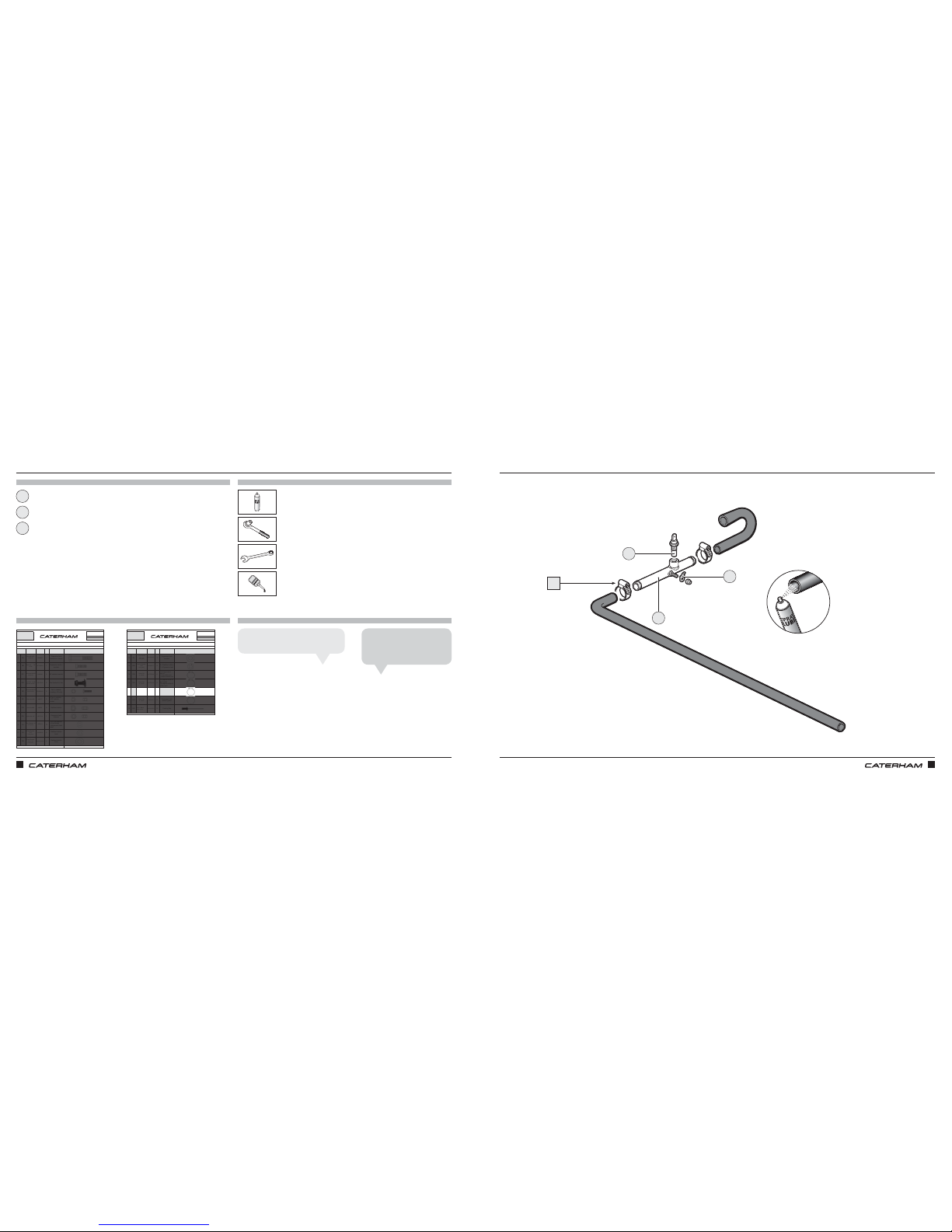
SUB-ASSEMBLY – TEMPERATURE SENSORSUB-ASSEMBLY – TEMPERATURE SENSOR
PARTS TOOLS
TIPS
Temperature sender
Cooling submarine
Earth tag
7mm
13mm
10mm
1
3
2
Use a drop of Locktite on the sender.
Tiago O
Be careful not to over‑tighten
the sender.
Jamie A
1
3
2
LOCTITE
LOCTITE
DP
FIXINGS
x2
Page 32
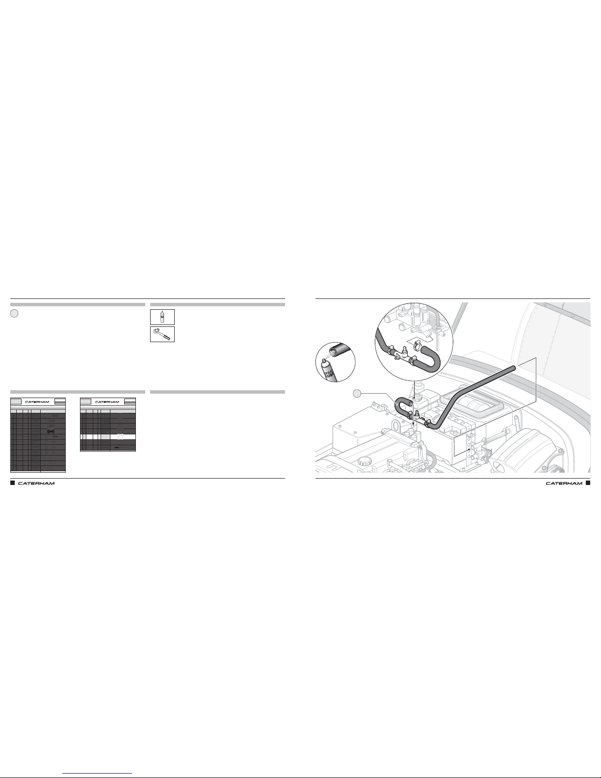
ASSEMBLY GUIDE ASSEMBLY GUIDE
54 55
PART
NUMBER
QTYUSED ON
1DA
BM8X50 1
Expansion tank
bracket to chassis
2DB
SF1/4X3/4
1
Expansion tank to
bracket
3DC
SM6X20
4 SV radiator bracket
4DD
30Z1072A
4Fan brackets to fan
5DE
SPHM6X16
4
Fan to radiator
cowling - SV only
6DF
NMYF6
8
x4 Fan to radiator
x4 SV radiator
bracket
7DG
NMPF8
8
Radiator bobbin
8DH
NFYF1/4
1
Expansion tank
bracket
9DI
WPH1/4
13
8 x SV rad bracket
4 x Fan fixings
1 x Expansion tank
braket
10 DJ
WPH5/16
4
Radiator bobbin
back
11 DK
WPH5/17X7/8
4
Radiator bobbin
front
Drawings are for illustrative purposes only and are not to scale.Page 1 of 2
Bolt M8 X 50
Grade 8.8
Plain Washer
5/16
"
Heavy duty
Nyloc Nut 1/4"
Plain Washer
1/4"
Heavy duty
Plain Washer
5/16" X 7/8"
Heavy duty
Setscrew M6X16
Panhead Pozi
Nyloc Nut M6
Plain Nut M8
Setscrew M8X20
Grade 8.8
COOLING SIGMA
This pack may include extra fasteners to cover different options
ITEM
BASIC
DESCRIPTION
ILLUSTRATION
Bolt M6 X 16 with
square section
Setscrew 1/4"
X 3/4"
D
SERIAL
NUMBER
44
Pack
PACK NUMBER
30C047B
PART
NUMBER
QTYUSED ON
12 DL
WPH1/4X7/8
1
Expansion tank
bracket
13 DM
WSH5/17
9
8 x Radiator bobbin
1 x Expansion tank
14 DN
SGT25-40
6
2 x U shape hose to
water rail
2 x Top radiator hose
2 x Bottom radiator hose
15 DO
SGT23-35
2
1 x Engine outlet to
big T piece
1 x Engine outlet to
heater inlet
16 DP
SGT16-25
18
6 x Heater inlet/outlet
3 x Big T-piece
1 x Expansion tank
2 x Modine
4 x Dry Sump
2 x Submarine
17 DQ
SGT8-16
6
Expansion tank
small T-piece
18 DR
1610-01015
12
Cowling flap
Drawings are for illustrative purposes only and are not to scale.Page 1 of 2
Plain Washer
1/4
" X 7/8"
Heavy duty
Page 1 of 2
Rivet - Black
5/32" X 0.47"
Hose Clip
17 - 25mm
Hose Clip
8 - 16mm
Hose Clip
30 - 40mm
Hose Clip
23 - 35mm
COOLING SIGMA
This pack may include extra fasteners to cover different options
ITEM
BASIC
DESCRIPTION
ILLUSTRATION
Spring Washer
5/16"
Heavy duty
D
SERIAL
NUMBER
44
Pack
PACK NUMBER
30C047B
BACK TO THE PLUMBINGBACK TO THE PLUMBING
PARTS
FIXINGS
TOOLS
TIPS
Submarine assembly
7mm
x1
1
1
Page 33
ASSEMBLY GUIDE ASSEMBLY GUIDE
56 57
PART
NUMBER
QTYUSED ON
1DA
BM8X50 1
Expansion tank
bracket to chassis
2DB
SF1/4X3/4
1
Expansion tank to
bracket
3DC
SM6X20
4 SV radiator bracket
4DD
30Z1072A
4Fan brackets to fan
5DE
SPHM6X16
4
Fan to radiator
cowling - SV only
6DF
NMYF6
8
x4 Fan to radiator
x4 SV radiator
bracket
7DG
NMPF8
8
Radiator bobbin
8DH
NFYF1/4
1
Expansion tank
bracket
9DI
WPH1/4
13
8 x SV rad bracket
4 x Fan fixings
1 x Expansion tank
braket
10 DJ
WPH5/16
4
Radiator bobbin
back
11 DK
WPH5/17X7/8
4
Radiator bobbin
front
Drawings are for illustrative purposes only and are not to scale.Page 1 of 2
Bolt M8 X 50
Grade 8.8
Plain Washer
5/16
"
Heavy duty
Nyloc Nut 1/4"
Plain Washer
1/4"
Heavy duty
Plain Washer
5/16" X 7/8"
Heavy duty
Setscrew M6X16
Panhead Pozi
Nyloc Nut M6
Plain Nut M8
Setscrew M8X20
Grade 8.8
COOLING SIGMA
This pack may include extra fasteners to cover different options
ITEM
BASIC
DESCRIPTION
ILLUSTRATION
Bolt M6 X 16 with
square section
Setscrew 1/4"
X 3/4"
D
SERIAL
NUMBER
44
Pack
PACK NUMBER
30C047B
PART
NUMBER
QTYUSED ON
12 DL
WPH1/4X7/8
1
Expansion tank
bracket
13 DM
WSH5/17
9
8 x Radiator bobbin
1 x Expansion tank
14 DN
SGT25-40
6
2 x U shape hose to
water rail
2 x Top radiator hose
2 x Bottom radiator hose
15 DO
SGT23-35
2
1 x Engine outlet to
big T piece
1 x Engine outlet to
heater inlet
16 DP
SGT16-25
18
6 x Heater inlet/outlet
3 x Big T-piece
1 x Expansion tank
2 x Modine
4 x Dry Sump
2 x Submarine
17 DQ
SGT8-16
6
Expansion tank
small T-piece
18 DR
1610-01015
12
Cowling flap
Drawings are for illustrative purposes only and are not to scale.Page 1 of 2
Plain Washer
1/4
" X 7/8"
Heavy duty
Page 1 of 2
Rivet - Black
5/32" X 0.47"
Hose Clip
17 - 25mm
Hose Clip
8 - 16mm
Hose Clip
30 - 40mm
Hose Clip
23 - 35mm
COOLING SIGMA
This pack may include extra fasteners to cover different options
ITEM
BASIC
DESCRIPTION
ILLUSTRATION
Spring Washer
5/16"
Heavy duty
D
SERIAL
NUMBER
44
Pack
PACK NUMBER
30C047B
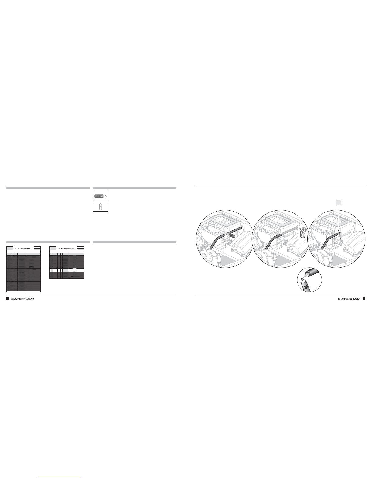
MORE PLUMBINGMORE PLUMBING
PARTS
FIXINGS
TOOLS
TIPS
x1
DP
Page 34
ASSEMBLY GUIDE ASSEMBLY GUIDE
58 59
PART
NUMBER
QTYUSED ON
1DA
BM8X50 1
Expansion tank
bracket to chassis
2DB
SF1/4X3/4
1
Expansion tank to
bracket
3DC
SM6X20
4 SV radiator bracket
4DD
30Z1072A
4Fan brackets to fan
5DE
SPHM6X16
4
Fan to radiator
cowling - SV only
6DF
NMYF6
8
x4 Fan to radiator
x4 SV radiator
bracket
7DG
NMPF8
8
Radiator bobbin
8DH
NFYF1/4
1
Expansion tank
bracket
9DI
WPH1/4
13
8 x SV rad bracket
4 x Fan fixings
1 x Expansion tank
braket
10 DJ
WPH5/16
4
Radiator bobbin
back
11 DK
WPH5/17X7/8
4
Radiator bobbin
front
Drawings are for illustrative purposes only and are not to scale.Page 1 of 2
Bolt M8 X 50
Grade 8.8
Plain Washer
5/16
"
Heavy duty
Nyloc Nut 1/4"
Plain Washer
1/4"
Heavy duty
Plain Washer
5/16" X 7/8"
Heavy duty
Setscrew M6X16
Panhead Pozi
Nyloc Nut M6
Plain Nut M8
Setscrew M8X20
Grade 8.8
COOLING SIGMA
This pack may include extra fasteners to cover different options
ITEM
BASIC
DESCRIPTION
ILLUSTRATION
Bolt M6 X 16 with
square section
Setscrew 1/4"
X 3/4"
D
SERIAL
NUMBER
44
Pack
PACK NUMBER
30C047B
PART
NUMBER
QTYUSED ON
12 DL
WPH1/4X7/8
1
Expansion tank
bracket
13 DM
WSH5/17
9
8 x Radiator bobbin
1 x Expansion tank
14 DN
SGT25-40
6
2 x U shape hose to
water rail
2 x Top radiator hose
2 x Bottom radiator hose
15 DO
SGT23-35
2
1 x Engine outlet to
big T piece
1 x Engine outlet to
heater inlet
16 DP
SGT16-25
18
6 x Heater inlet/outlet
3 x Big T-piece
1 x Expansion tank
2 x Modine
4 x Dry Sump
2 x Submarine
17 DQ
SGT8-16
6
Expansion tank
small T-piece
18 DR
1610-01015
12
Cowling flap
Drawings are for illustrative purposes only and are not to scale.Page 1 of 2
Plain Washer
1/4
" X 7/8"
Heavy duty
Page 1 of 2
Rivet - Black
5/32" X 0.47"
Hose Clip
17 - 25mm
Hose Clip
8 - 16mm
Hose Clip
30 - 40mm
Hose Clip
23 - 35mm
COOLING SIGMA
This pack may include extra fasteners to cover different options
ITEM
BASIC
DESCRIPTION
ILLUSTRATION
Spring Washer
5/16"
Heavy duty
D
SERIAL
NUMBER
44
Pack
PACK NUMBER
30C047B
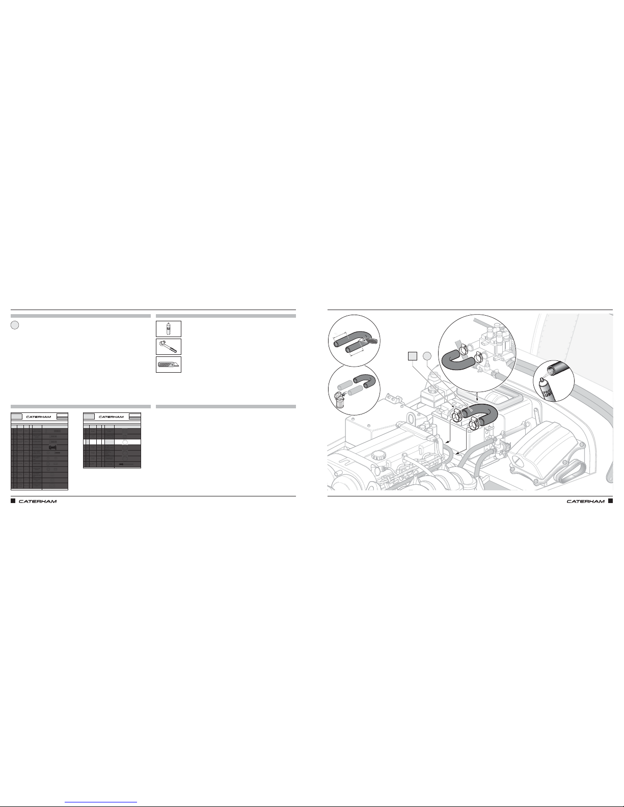
STILL MORE PLUMBINGSTILL MORE PLUMBING
PARTS
FIXINGS
TOOLS
TIPS
U shape hose
x2
1
7mm
DN
120mm
120mm
1
Page 35
ASSEMBLY GUIDE ASSEMBLY GUIDE
60 61
PART
NUMBER
QTYUSED ON
1DA
BM8X50 1
Expansion tank
bracket to chassis
2DB
SF1/4X3/4
1
Expansion tank to
bracket
3DC
SM6X20
4 SV radiator bracket
4DD
30Z1072A
4Fan brackets to fan
5DE
SPHM6X16
4
Fan to radiator
cowling - SV only
6DF
NMYF6
8
x4 Fan to radiator
x4 SV radiator
bracket
7DG
NMPF8
8
Radiator bobbin
8DH
NFYF1/4
1
Expansion tank
bracket
9DI
WPH1/4
13
8 x SV rad bracket
4 x Fan fixings
1 x Expansion tank
braket
10 DJ
WPH5/16
4
Radiator bobbin
back
11 DK
WPH5/17X7/8
4
Radiator bobbin
front
Drawings are for illustrative purposes only and are not to scale.Page 1 of 2
Bolt M8 X 50
Grade 8.8
Plain Washer
5/16
"
Heavy duty
Nyloc Nut 1/4"
Plain Washer
1/4"
Heavy duty
Plain Washer
5/16" X 7/8"
Heavy duty
Setscrew M6X16
Panhead Pozi
Nyloc Nut M6
Plain Nut M8
Setscrew M8X20
Grade 8.8
COOLING SIGMA
This pack may include extra fasteners to cover different options
ITEM
BASIC
DESCRIPTION
ILLUSTRATION
Bolt M6 X 16 with
square section
Setscrew 1/4"
X 3/4"
D
SERIAL
NUMBER
44
Pack
PACK NUMBER
30C047B
PART
NUMBER
QTYUSED ON
12 DL
WPH1/4X7/8
1
Expansion tank
bracket
13 DM
WSH5/17
9
8 x Radiator bobbin
1 x Expansion tank
14 DN
SGT25-40
6
2 x U shape hose to
water rail
2 x Top radiator hose
2 x Bottom radiator hose
15 DO
SGT23-35
2
1 x Engine outlet to
big T piece
1 x Engine outlet to
heater inlet
16 DP
SGT16-25
18
6 x Heater inlet/outlet
3 x Big T-piece
1 x Expansion tank
2 x Modine
4 x Dry Sump
2 x Submarine
17 DQ
SGT8-16
6
Expansion tank
small T-piece
18 DR
1610-01015
12
Cowling flap
Drawings are for illustrative purposes only and are not to scale.Page 1 of 2
Plain Washer
1/4
" X 7/8"
Heavy duty
Page 1 of 2
Rivet - Black
5/32" X 0.47"
Hose Clip
17 - 25mm
Hose Clip
8 - 16mm
Hose Clip
30 - 40mm
Hose Clip
23 - 35mm
COOLING SIGMA
This pack may include extra fasteners to cover different options
ITEM
BASIC
DESCRIPTION
ILLUSTRATION
Spring Washer
5/16"
Heavy duty
D
SERIAL
NUMBER
44
Pack
PACK NUMBER
30C047B
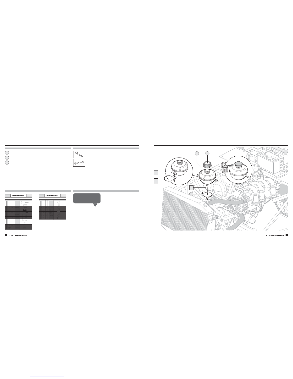
A BREAK FROM PLUMBING TO FIT THE EXPANSION BOTTLEA BREAK FROM PLUMBING TO FIT THE EXPANSION BOTTLE
PARTS
FIXINGS
TOOLS
TIPS
x1
x1
x1
x1
x1
13mm
11mm
Expansion bottle
Expansion bottle bracket
Expansion bottle cap
11mm
x1
1
3
2
DH
DI
DB
DL
1 2
3
DA
DM
Throw away the red cap that
came on the expansion bottle.
Grant P
Page 36
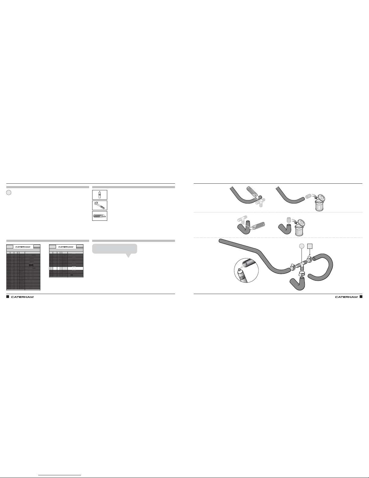
ASSEMBLY GUIDE ASSEMBLY GUIDE
62 63
PART
NUMBER
QTYUSED ON
1DA
BM8X50 1
Expansion tank
bracket to chassis
2DB
SF1/4X3/4
1
Expansion tank to
bracket
3DC
SM6X20
4 SV radiator bracket
4DD
30Z1072A
4Fan brackets to fan
5DE
SPHM6X16
4
Fan to radiator
cowling - SV only
6DF
NMYF6
8
x4 Fan to radiator
x4 SV radiator
bracket
7DG
NMPF8
8
Radiator bobbin
8DH
NFYF1/4
1
Expansion tank
bracket
9DI
WPH1/4
13
8 x SV rad bracket
4 x Fan fixings
1 x Expansion tank
braket
10 DJ
WPH5/16
4
Radiator bobbin
back
11 DK
WPH5/17X7/8
4
Radiator bobbin
front
Drawings are for illustrative purposes only and are not to scale.Page 1 of 2
Bolt M8 X 50
Grade 8.8
Plain Washer
5/16
"
Heavy duty
Nyloc Nut 1/4"
Plain Washer
1/4"
Heavy duty
Plain Washer
5/16" X 7/8"
Heavy duty
Setscrew M6X16
Panhead Pozi
Nyloc Nut M6
Plain Nut M8
Setscrew M8X20
Grade 8.8
COOLING SIGMA
This pack may include extra fasteners to cover different options
ITEM
BASIC
DESCRIPTION
ILLUSTRATION
Bolt M6 X 16 with
square section
Setscrew 1/4"
X 3/4"
D
SERIAL
NUMBER
44
Pack
PACK NUMBER
30C047B
PART
NUMBER
QTYUSED ON
12 DL
WPH1/4X7/8
1
Expansion tank
bracket
13 DM
WSH5/17
9
8 x Radiator bobbin
1 x Expansion tank
14 DN
SGT25-40
6
2 x U shape hose to
water rail
2 x Top radiator hose
2 x Bottom radiator hose
15 DO
SGT23-35
2
1 x Engine outlet to
big T piece
1 x Engine outlet to
heater inlet
16 DP
SGT16-25
18
6 x Heater inlet/outlet
3 x Big T-piece
1 x Expansion tank
2 x Modine
4 x Dry Sump
2 x Submarine
17 DQ
SGT8-16
6
Expansion tank
small T-piece
18 DR
1610-01015
12
Cowling flap
Drawings are for illustrative purposes only and are not to scale.Page 1 of 2
Plain Washer
1/4
" X 7/8"
Heavy duty
Page 1 of 2
Rivet - Black
5/32" X 0.47"
Hose Clip
17 - 25mm
Hose Clip
8 - 16mm
Hose Clip
30 - 40mm
Hose Clip
23 - 35mm
COOLING SIGMA
This pack may include extra fasteners to cover different options
ITEM
BASIC
DESCRIPTION
ILLUSTRATION
Spring Washer
5/16"
Heavy duty
D
SERIAL
NUMBER
44
Pack
PACK NUMBER
30C047B
SOME MORE HOSE MODIFICATIONSOME MORE HOSE MODIFICATION
PARTS
FIXINGS
TOOLS
TIPS
T-Piece
x3
1
7mm
DP
The short 'L' shaped hose is pre‑formed.
John S
1
Page 37
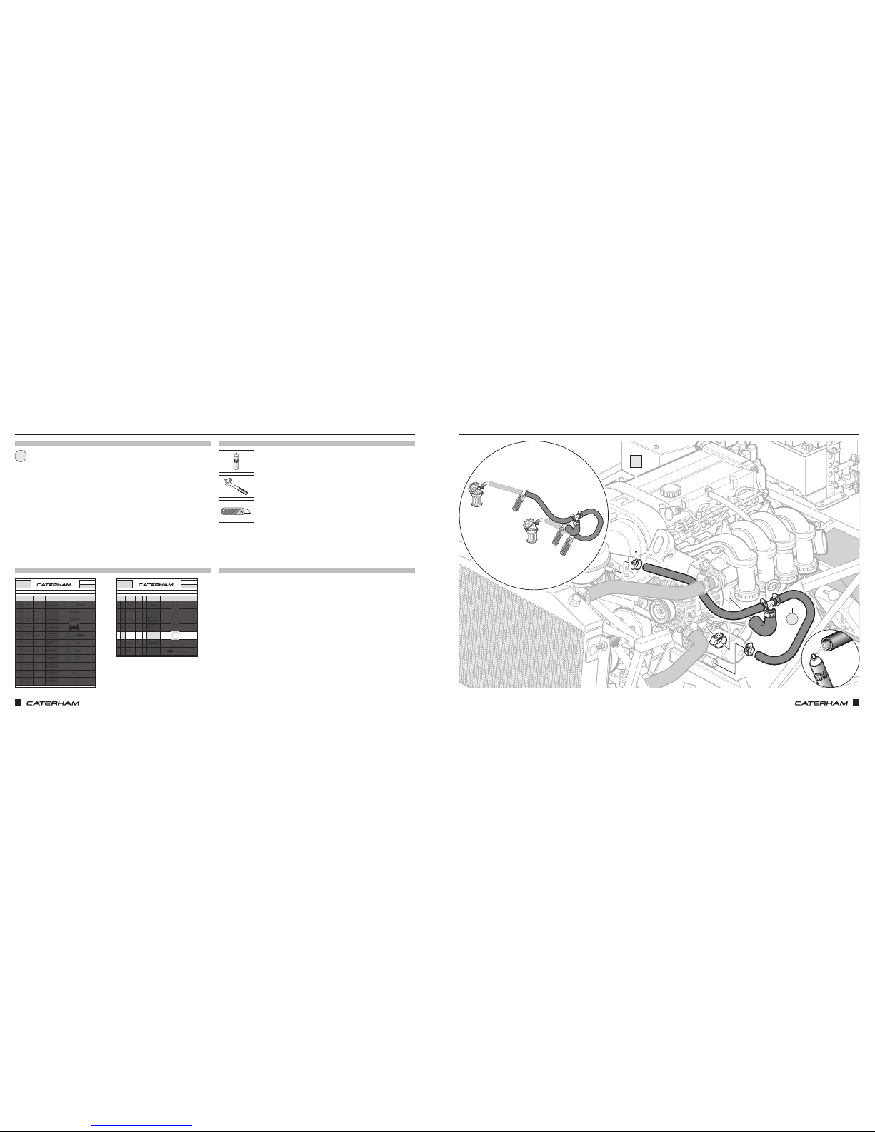
ASSEMBLY GUIDE ASSEMBLY GUIDE
64 65
PART
NUMBER
QTYUSED ON
1DA
BM8X50 1
Expansion tank
bracket to chassis
2DB
SF1/4X3/4
1
Expansion tank to
bracket
3DC
SM6X20
4 SV radiator bracket
4DD
30Z1072A
4Fan brackets to fan
5DE
SPHM6X16
4
Fan to radiator
cowling - SV only
6DF
NMYF6
8
x4 Fan to radiator
x4 SV radiator
bracket
7DG
NMPF8
8
Radiator bobbin
8DH
NFYF1/4
1
Expansion tank
bracket
9DI
WPH1/4
13
8 x SV rad bracket
4 x Fan fixings
1 x Expansion tank
braket
10 DJ
WPH5/16
4
Radiator bobbin
back
11 DK
WPH5/17X7/8
4
Radiator bobbin
front
Drawings are for illustrative purposes only and are not to scale.Page 1 of 2
Bolt M8 X 50
Grade 8.8
Plain Washer
5/16
"
Heavy duty
Nyloc Nut 1/4"
Plain Washer
1/4"
Heavy duty
Plain Washer
5/16" X 7/8"
Heavy duty
Setscrew M6X16
Panhead Pozi
Nyloc Nut M6
Plain Nut M8
Setscrew M8X20
Grade 8.8
COOLING SIGMA
This pack may include extra fasteners to cover different options
ITEM
BASIC
DESCRIPTION
ILLUSTRATION
Bolt M6 X 16 with
square section
Setscrew 1/4"
X 3/4"
D
SERIAL
NUMBER
44
Pack
PACK NUMBER
30C047B
PART
NUMBER
QTYUSED ON
12 DL
WPH1/4X7/8
1
Expansion tank
bracket
13 DM
WSH5/17
9
8 x Radiator bobbin
1 x Expansion tank
14 DN
SGT25-40
6
2 x U shape hose to
water rail
2 x Top radiator hose
2 x Bottom radiator hose
15 DO
SGT23-35
2
1 x Engine outlet to
big T piece
1 x Engine outlet to
heater inlet
16 DP
SGT16-25
18
6 x Heater inlet/outlet
3 x Big T-piece
1 x Expansion tank
2 x Modine
4 x Dry Sump
2 x Submarine
17 DQ
SGT8-16
6
Expansion tank
small T-piece
18 DR
1610-01015
12
Cowling flap
Drawings are for illustrative purposes only and are not to scale.Page 1 of 2
Plain Washer
1/4
" X 7/8"
Heavy duty
Page 1 of 2
Rivet - Black
5/32" X 0.47"
Hose Clip
17 - 25mm
Hose Clip
8 - 16mm
Hose Clip
30 - 40mm
Hose Clip
23 - 35mm
COOLING SIGMA
This pack may include extra fasteners to cover different options
ITEM
BASIC
DESCRIPTION
ILLUSTRATION
Spring Washer
5/16"
Heavy duty
D
SERIAL
NUMBER
44
Pack
PACK NUMBER
30C047B
AND BACK TO PLUMBINGAND BACK TO PLUMBING
PARTS
FIXINGS
TOOLS
TIPS
x1
7mm
DP
T-Piece assembly
1
1
Page 38
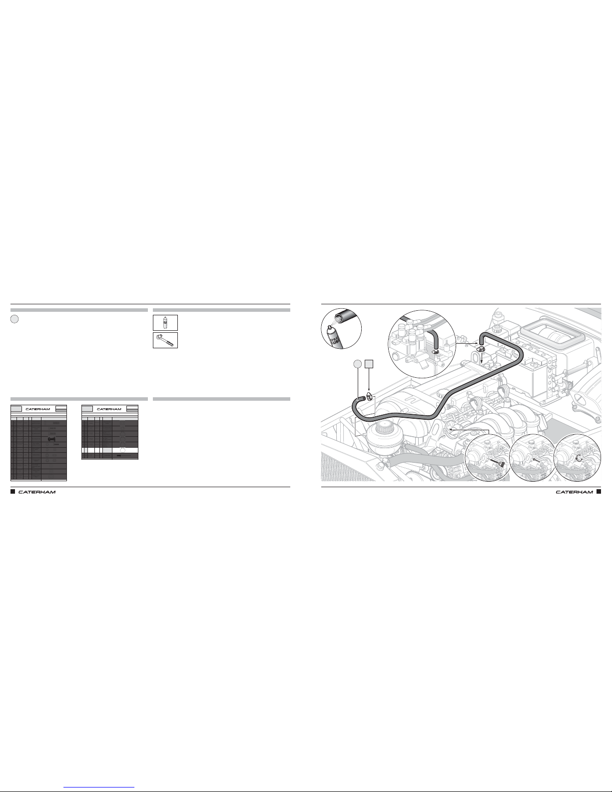
ASSEMBLY GUIDE ASSEMBLY GUIDE
66 67
PART
NUMBER
QTYUSED ON
1DA
BM8X50 1
Expansion tank
bracket to chassis
2DB
SF1/4X3/4
1
Expansion tank to
bracket
3DC
SM6X20
4 SV radiator bracket
4DD
30Z1072A
4Fan brackets to fan
5DE
SPHM6X16
4
Fan to radiator
cowling - SV only
6DF
NMYF6
8
x4 Fan to radiator
x4 SV radiator
bracket
7DG
NMPF8
8
Radiator bobbin
8DH
NFYF1/4
1
Expansion tank
bracket
9DI
WPH1/4
13
8 x SV rad bracket
4 x Fan fixings
1 x Expansion tank
braket
10 DJ
WPH5/16
4
Radiator bobbin
back
11 DK
WPH5/17X7/8
4
Radiator bobbin
front
Drawings are for illustrative purposes only and are not to scale.Page 1 of 2
Bolt M8 X 50
Grade 8.8
Plain Washer
5/16
"
Heavy duty
Nyloc Nut 1/4"
Plain Washer
1/4"
Heavy duty
Plain Washer
5/16" X 7/8"
Heavy duty
Setscrew M6X16
Panhead Pozi
Nyloc Nut M6
Plain Nut M8
Setscrew M8X20
Grade 8.8
COOLING SIGMA
This pack may include extra fasteners to cover different options
ITEM
BASIC
DESCRIPTION
ILLUSTRATION
Bolt M6 X 16 with
square section
Setscrew 1/4"
X 3/4"
D
SERIAL
NUMBER
44
Pack
PACK NUMBER
30C047B
PART
NUMBER
QTYUSED ON
12 DL
WPH1/4X7/8
1
Expansion tank
bracket
13 DM
WSH5/17
9
8 x Radiator bobbin
1 x Expansion tank
14 DN
SGT25-40
6
2 x U shape hose to
water rail
2 x Top radiator hose
2 x Bottom radiator hose
15 DO
SGT23-35
2
1 x Engine outlet to
big T piece
1 x Engine outlet to
heater inlet
16 DP
SGT16-25
18
6 x Heater inlet/outlet
3 x Big T-piece
1 x Expansion tank
2 x Modine
4 x Dry Sump
2 x Submarine
17 DQ
SGT8-16
6
Expansion tank
small T-piece
18 DR
1610-01015
12
Cowling flap
Drawings are for illustrative purposes only and are not to scale.Page 1 of 2
Plain Washer
1/4
" X 7/8"
Heavy duty
Page 1 of 2
Rivet - Black
5/32" X 0.47"
Hose Clip
17 - 25mm
Hose Clip
8 - 16mm
Hose Clip
30 - 40mm
Hose Clip
23 - 35mm
COOLING SIGMA
This pack may include extra fasteners to cover different options
ITEM
BASIC
DESCRIPTION
ILLUSTRATION
Spring Washer
5/16"
Heavy duty
D
SERIAL
NUMBER
44
Pack
PACK NUMBER
30C047B
LAST BIT OF PLUMBINGLAST BIT OF PLUMBING
PARTS
FIXINGS
TOOLS
TIPS
⅝ Hose
x2
1
7mm
DQ
1
Page 39
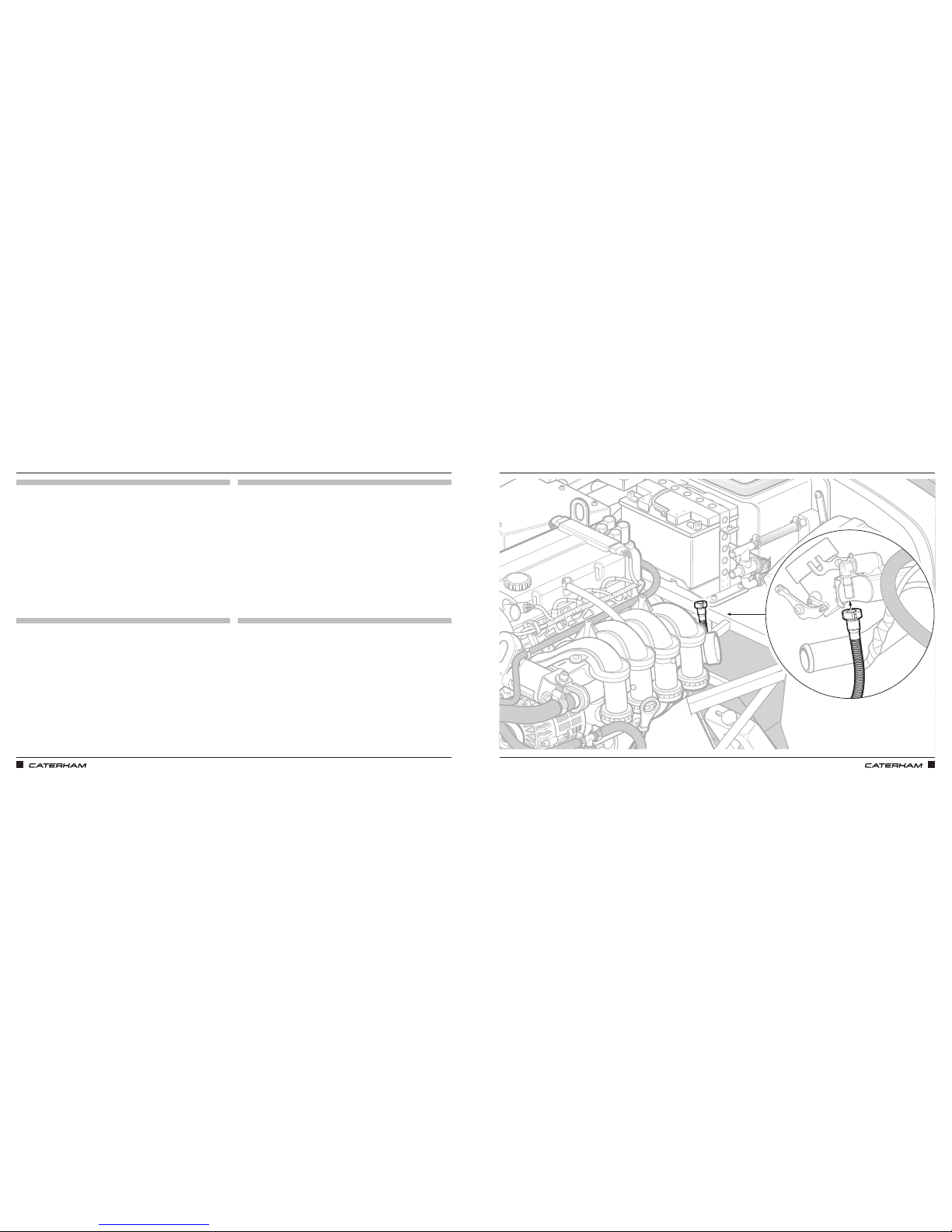
ASSEMBLY GUIDE ASSEMBLY GUIDE
68 69
CONNECTING THE FUEL LINECONNECTING THE FUEL LINE
PARTS
FIXINGS
TOOLS
TIPS
Page 40
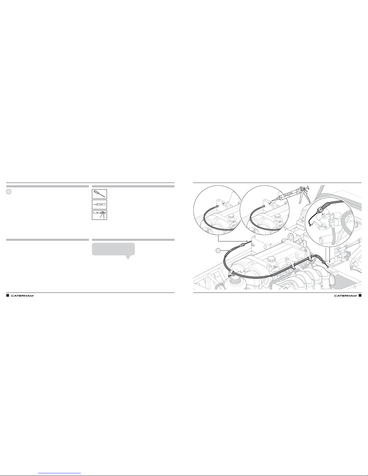
ASSEMBLY GUIDE ASSEMBLY GUIDE
70 71
PARTS
FIXINGS
TOOLS
TIPS
Throttle cable
1
FIT THROTTLE CABLEFIT THROTTLE CABLE
1
Fixings are supplied loosely attached to the engine in place
The silicone goes in the top of the
pedal to prevent the cable coming out.
Rich T
Page 41
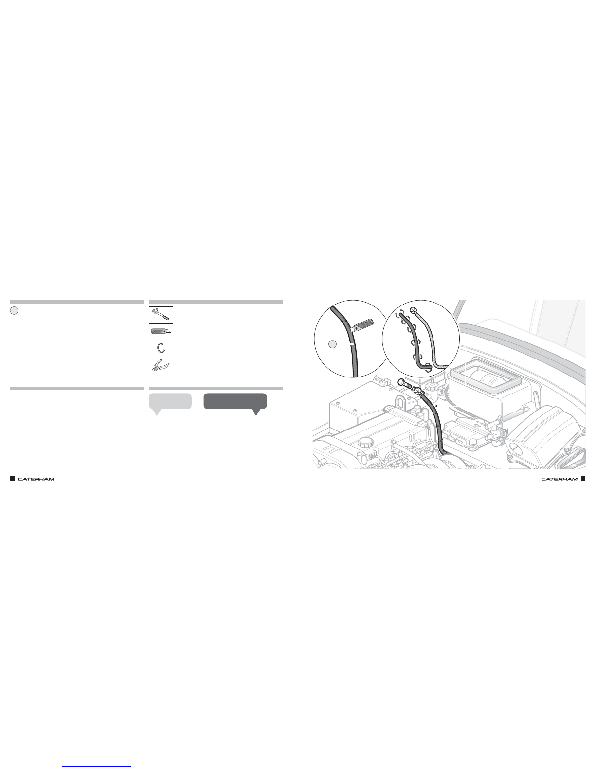
ASSEMBLY GUIDE ASSEMBLY GUIDE
72 73
PROTECTING & ATTACHING THE CLUTCH HOSEPROTECTING & ATTACHING THE CLUTCH HOSE
PARTS
FIXINGS
TOOLS
TIPS
14mm
8mm water hose
1
1
Nip up the banjo bolt.
John K
The hose is used to stop chaffing.
James A
Page 42
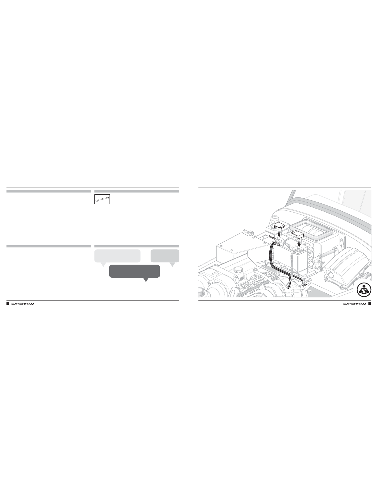
ASSEMBLY GUIDE ASSEMBLY GUIDE
74 75
CONNECTING THE BATTERY (POSITIVE / RED FIRST)
PARTS
FIXINGS
TOOLS
TIPS
CONNECTING THE BATTERY (POSITIVE / RED FIRST)
10mm (x2)
Always connect live side of battery first
(red wire).
Chris B
Be careful to ensure that the red leads go to
the + side and the black wires to the – side.
Dan D
Make the battery the
last thing you connect.
Jamie A
Page 43
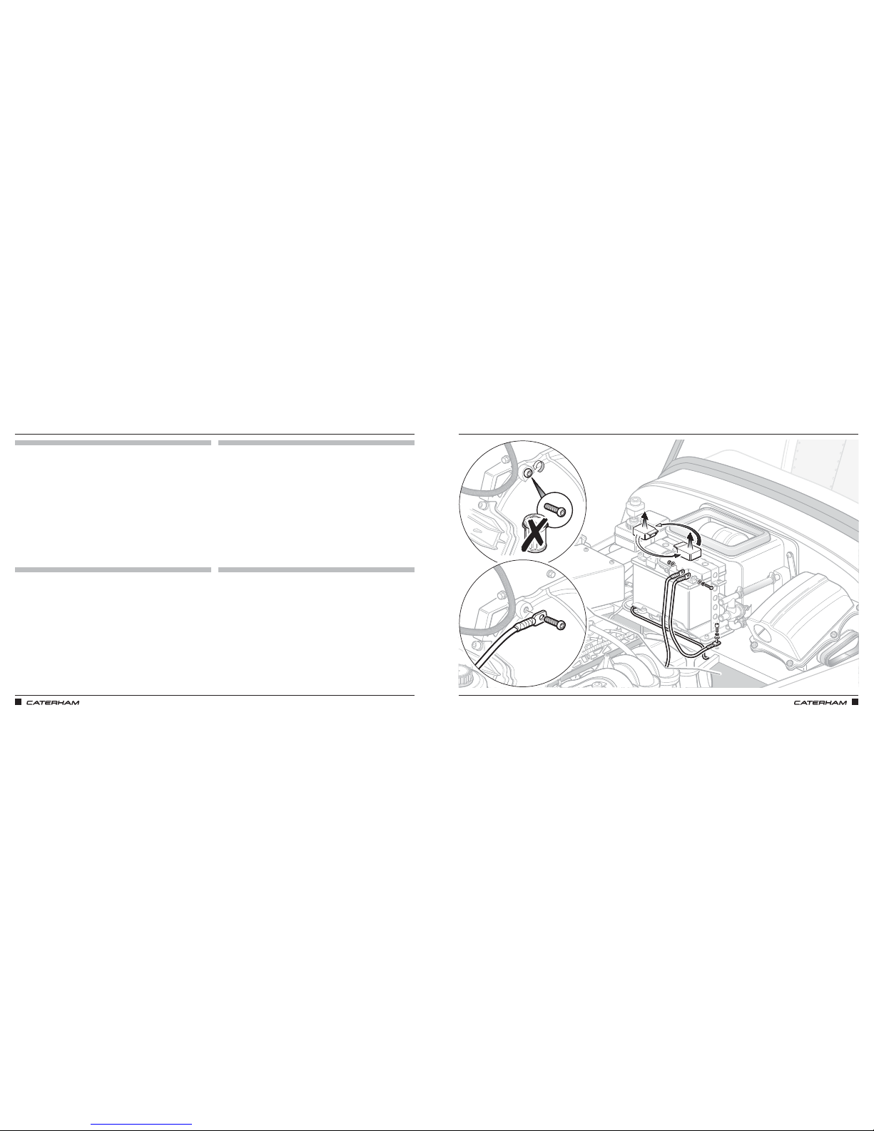
ASSEMBLY GUIDE ASSEMBLY GUIDE
76 77
IT LIVES!IT LIVES!
PARTS
FIXINGS
TOOLS
TIPS
Page 44
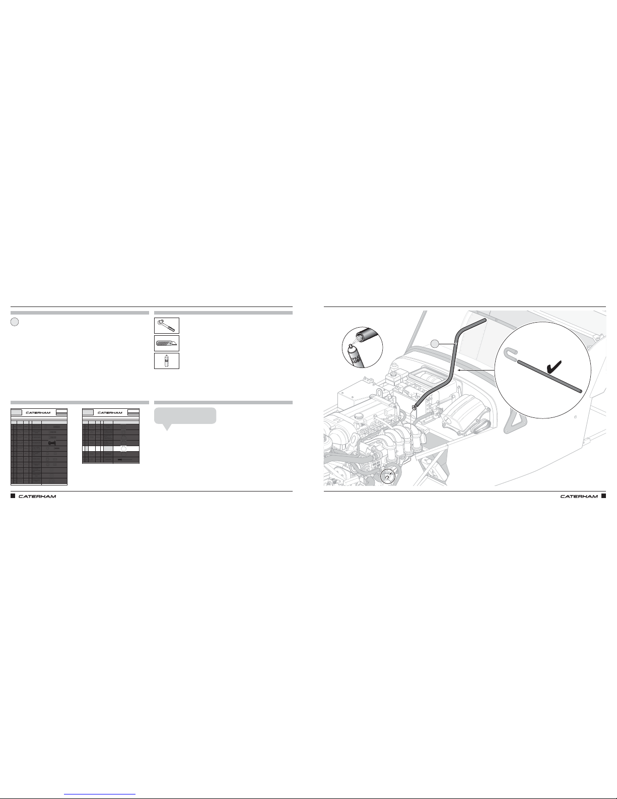
ASSEMBLY GUIDE ASSEMBLY GUIDE
78 79
PART
NUMBER
QTYUSED ON
1DA
BM8X50 1
Expansion tank
bracket to chassis
2DB
SF1/4X3/4
1
Expansion tank to
bracket
3DC
SM6X20
4 SV radiator bracket
4DD
30Z1072A
4Fan brackets to fan
5DE
SPHM6X16
4
Fan to radiator
cowling - SV only
6DF
NMYF6
8
x4 Fan to radiator
x4 SV radiator
bracket
7DG
NMPF8
8
Radiator bobbin
8DH
NFYF1/4
1
Expansion tank
bracket
9DI
WPH1/4
13
8 x SV rad bracket
4 x Fan fixings
1 x Expansion tank
braket
10 DJ
WPH5/16
4
Radiator bobbin
back
11 DK
WPH5/17X7/8
4
Radiator bobbin
front
Drawings are for illustrative purposes only and are not to scale.Page 1 of 2
Bolt M8 X 50
Grade 8.8
Plain Washer
5/16
"
Heavy duty
Nyloc Nut 1/4"
Plain Washer
1/4"
Heavy duty
Plain Washer
5/16" X 7/8"
Heavy duty
Setscrew M6X16
Panhead Pozi
Nyloc Nut M6
Plain Nut M8
Setscrew M8X20
Grade 8.8
COOLING SIGMA
This pack may include extra fasteners to cover different options
ITEM
BASIC
DESCRIPTION
ILLUSTRATION
Bolt M6 X 16 with
square section
Setscrew 1/4"
X 3/4"
D
SERIAL
NUMBER
44
Pack
PACK NUMBER
30C047B
PART
NUMBER
QTYUSED ON
12 DL
WPH1/4X7/8
1
Expansion tank
bracket
13 DM
WSH5/17
9
8 x Radiator bobbin
1 x Expansion tank
14 DN
SGT25-40
6
2 x U shape hose to
water rail
2 x Top radiator hose
2 x Bottom radiator hose
15 DO
SGT23-35
2
1 x Engine outlet to
big T piece
1 x Engine outlet to
heater inlet
16 DP
SGT16-25
18
6 x Heater inlet/outlet
3 x Big T-piece
1 x Expansion tank
2 x Modine
4 x Dry Sump
2 x Submarine
17 DQ
SGT8-16
6
Expansion tank
small T-piece
18 DR
1610-01015
12
Cowling flap
Drawings are for illustrative purposes only and are not to scale.Page 1 of 2
Plain Washer
1/4
" X 7/8"
Heavy duty
Page 1 of 2
Rivet - Black
5/32" X 0.47"
Hose Clip
17 - 25mm
Hose Clip
8 - 16mm
Hose Clip
30 - 40mm
Hose Clip
23 - 35mm
COOLING SIGMA
This pack may include extra fasteners to cover different options
ITEM
BASIC
DESCRIPTION
ILLUSTRATION
Spring Washer
5/16"
Heavy duty
D
SERIAL
NUMBER
44
Pack
PACK NUMBER
30C047B
ONE LAST BIT OF PLUMBING…ONE LAST BIT OF PLUMBING…
PARTS
FIXINGS
TOOLS
TIPS
1
Hose
1
7mm
x1
Cut off hook and trim if required.
Grant P
Page 45
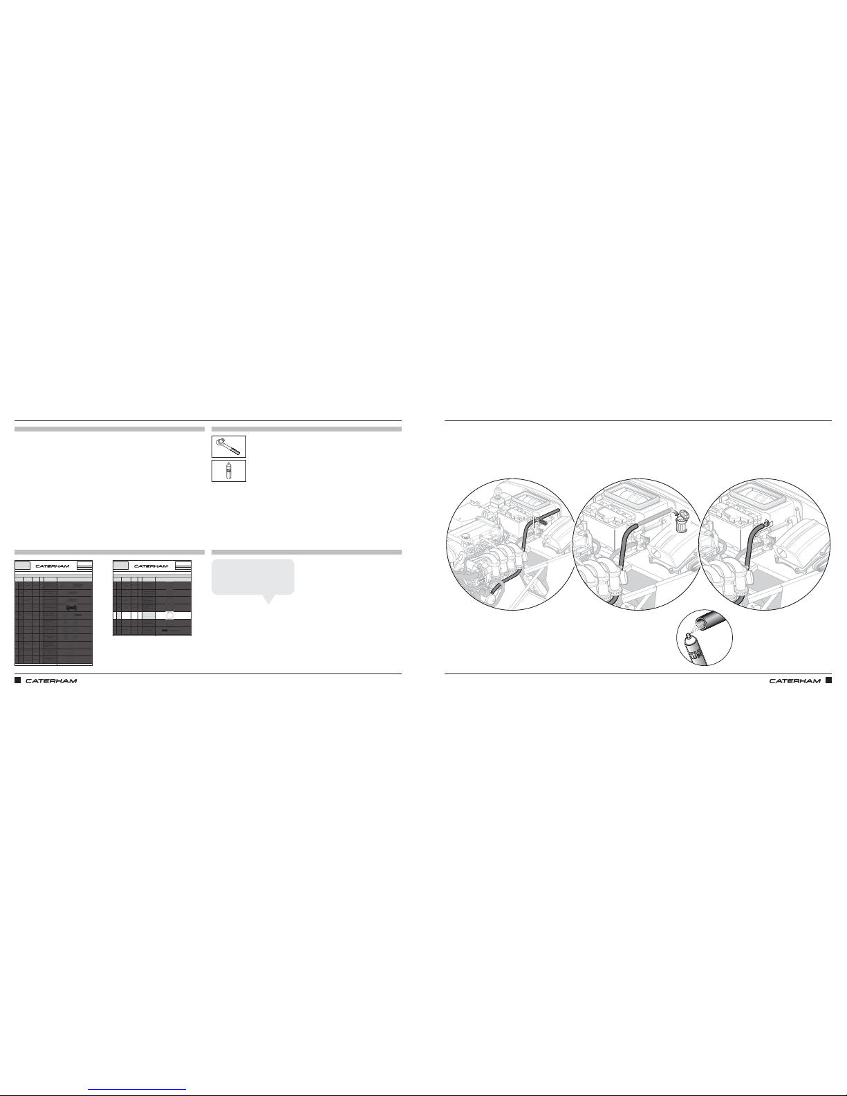
ASSEMBLY GUIDE ASSEMBLY GUIDE
80 81
PART
NUMBER
QTYUSED ON
1DA
BM8X50 1
Expansion tank
bracket to chassis
2DB
SF1/4X3/4
1
Expansion tank to
bracket
3DC
SM6X20
4 SV radiator bracket
4DD
30Z1072A
4Fan brackets to fan
5DE
SPHM6X16
4
Fan to radiator
cowling - SV only
6DF
NMYF6
8
x4 Fan to radiator
x4 SV radiator
bracket
7DG
NMPF8
8
Radiator bobbin
8DH
NFYF1/4
1
Expansion tank
bracket
9DI
WPH1/4
13
8 x SV rad bracket
4 x Fan fixings
1 x Expansion tank
braket
10 DJ
WPH5/16
4
Radiator bobbin
back
11 DK
WPH5/17X7/8
4
Radiator bobbin
front
Drawings are for illustrative purposes only and are not to scale.Page 1 of 2
Bolt M8 X 50
Grade 8.8
Plain Washer
5/16
"
Heavy duty
Nyloc Nut 1/4"
Plain Washer
1/4"
Heavy duty
Plain Washer
5/16" X 7/8"
Heavy duty
Setscrew M6X16
Panhead Pozi
Nyloc Nut M6
Plain Nut M8
Setscrew M8X20
Grade 8.8
COOLING SIGMA
This pack may include extra fasteners to cover different options
ITEM
BASIC
DESCRIPTION
ILLUSTRATION
Bolt M6 X 16 with
square section
Setscrew 1/4"
X 3/4"
D
SERIAL
NUMBER
44
Pack
PACK NUMBER
30C047B
PART
NUMBER
QTYUSED ON
12 DL
WPH1/4X7/8
1
Expansion tank
bracket
13 DM
WSH5/17
9
8 x Radiator bobbin
1 x Expansion tank
14 DN
SGT25-40
6
2 x U shape hose to
water rail
2 x Top radiator hose
2 x Bottom radiator hose
15 DO
SGT23-35
2
1 x Engine outlet to
big T piece
1 x Engine outlet to
heater inlet
16 DP
SGT16-25
18
6 x Heater inlet/outlet
3 x Big T-piece
1 x Expansion tank
2 x Modine
4 x Dry Sump
2 x Submarine
17 DQ
SGT8-16
6
Expansion tank
small T-piece
18 DR
1610-01015
12
Cowling flap
Drawings are for illustrative purposes only and are not to scale.Page 1 of 2
Plain Washer
1/4
" X 7/8"
Heavy duty
Page 1 of 2
Rivet - Black
5/32" X 0.47"
Hose Clip
17 - 25mm
Hose Clip
8 - 16mm
Hose Clip
30 - 40mm
Hose Clip
23 - 35mm
COOLING SIGMA
This pack may include extra fasteners to cover different options
ITEM
BASIC
DESCRIPTION
ILLUSTRATION
Spring Washer
5/16"
Heavy duty
D
SERIAL
NUMBER
44
Pack
PACK NUMBER
30C047B
…TO CONNECT THE HEATER…TO CONNECT THE HEATER
PARTS
FIXINGS
TOOLS
TIPS
7mm
x1
The coolant concentrate should
be diluted 50/50 with water. It
does not need to be exact!
Anthony L
Page 46
ASSEMBLY GUIDE ASSEMBLY GUIDE
82 83
PARTS
FIXINGS
TOOLS
TIPS
Coolant concentrate
FILL WITH COOLANTFILL WITH COOLANT
Fill expansion bottle to max mark
Page 47
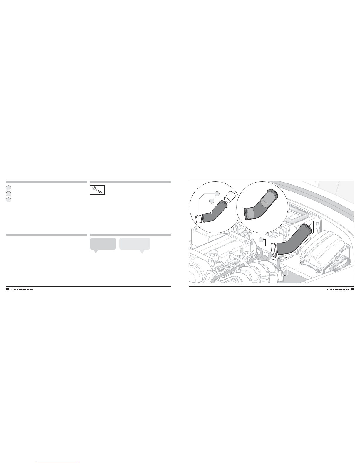
ASSEMBLY GUIDE ASSEMBLY GUIDE
84 85
CONNECT THE AIRBOX TO THE ENGINECONNECT THE AIRBOX TO THE ENGINE
PARTS
FIXINGS
TOOLS
TIPS
7mm
Airbox hose
Hose clip
Insert set
1
3
2
All fixings for this step should be in the supplied airbox box
To help push insert in
use the work bench.
Rich T
2
3
Spray brake cleaner in the
hose and on the insert.
John K
1
Page 48
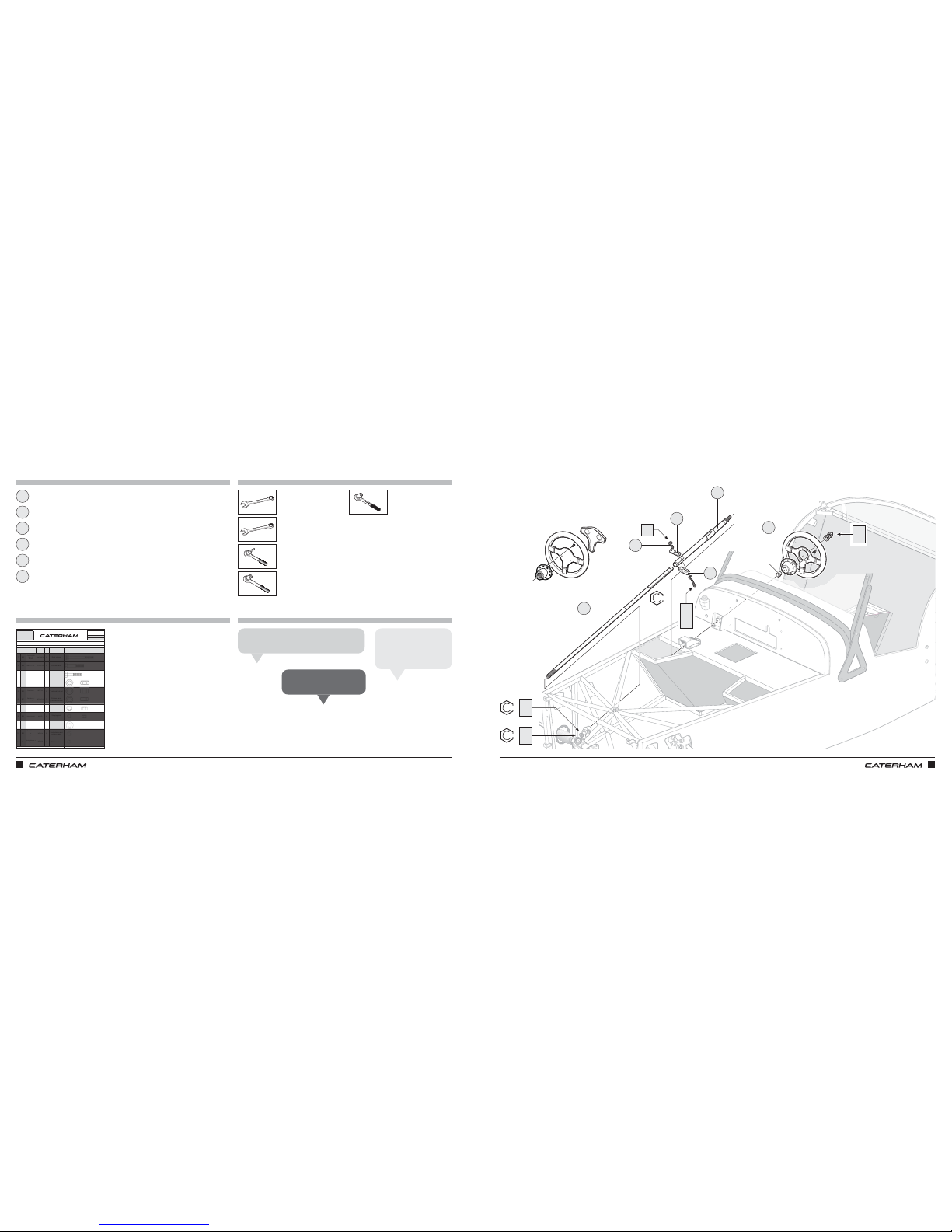
ASSEMBLY GUIDE ASSEMBLY GUIDE
86 87
PART
NUMBER
QTYUSED ON
1BA
BMCH6X70
4Rack clamps
2BB
BF1/4X1.1/2
2Column clamp
3BC
BM8X35
2
Column to rack
universal joint
4BD
NFYH1/2
1Steering wheel boss
5BE
NFPF1/2
2Track rod lock nut
6BF
NFPFH7/16
1
Column clamp
grubscrew locknut
7BG
NMYF8
2
Column to rack
universal joint
8BH
NMYF6
4
Steering rack
clamps
9BJ
WPH1/2
1
Steering wheel boss
10 BK
WPH1/4
6
Rack clamps and
column clamp
11 BL
WSH1/4
2
Column clamp
Drawings are for illustrative purposes only and are not to scale.
B
SERIAL
NUMBER
55
Pack
PACK NUMBER
30S003B
STEERING DeDION CARS (METRIC)
This pack may include extra fasteners to cover different options
ITEM
BASIC
DESCRIPTION
ILLUSTRATION
Caphead Bolt
M6 x 70
DIN 912
Bolt ¼" x 1½"
Bolt M8 x 35
Grade 8.8
Nyloc Nut ½"
Half height
Plain Nut ½"
Plain Nut ⁷⁄₁₆"
Half height
Nyloc Nut M8
Spring Washer ¼
Heavy duty
Page 1 of 1
Nyloc Nut M6
Plain Washer
½" x 1⅛"
Chamfered
Plain Washer
¼"
Heavy duty
7
PARTS
FIXINGS
TOOLS
TIPS
x2
x1
x2
x1
⁄"
11mm
Lower steering column
Steering column clamp
Steering column bush
Upper steering column
Grub screw
Steering column clamp plate
⁄"
⁄"
1
3
6
2
5
4
GIVING IT SOME DIRECTIONGIVING IT SOME DIRECTION
Put the clamp in the middle of column recess.
Jamie A
Grease the steering bushes.
Lee A
BF
5
4
1
Fit the clamp bolts first,
then grubscrew & finish
with the locking nut.
Tiago O
BC
BG
20Nm
14Nm
3
20Nm
BC
BG
2
BD
BJ
6
BB
BK
BL
Page 49
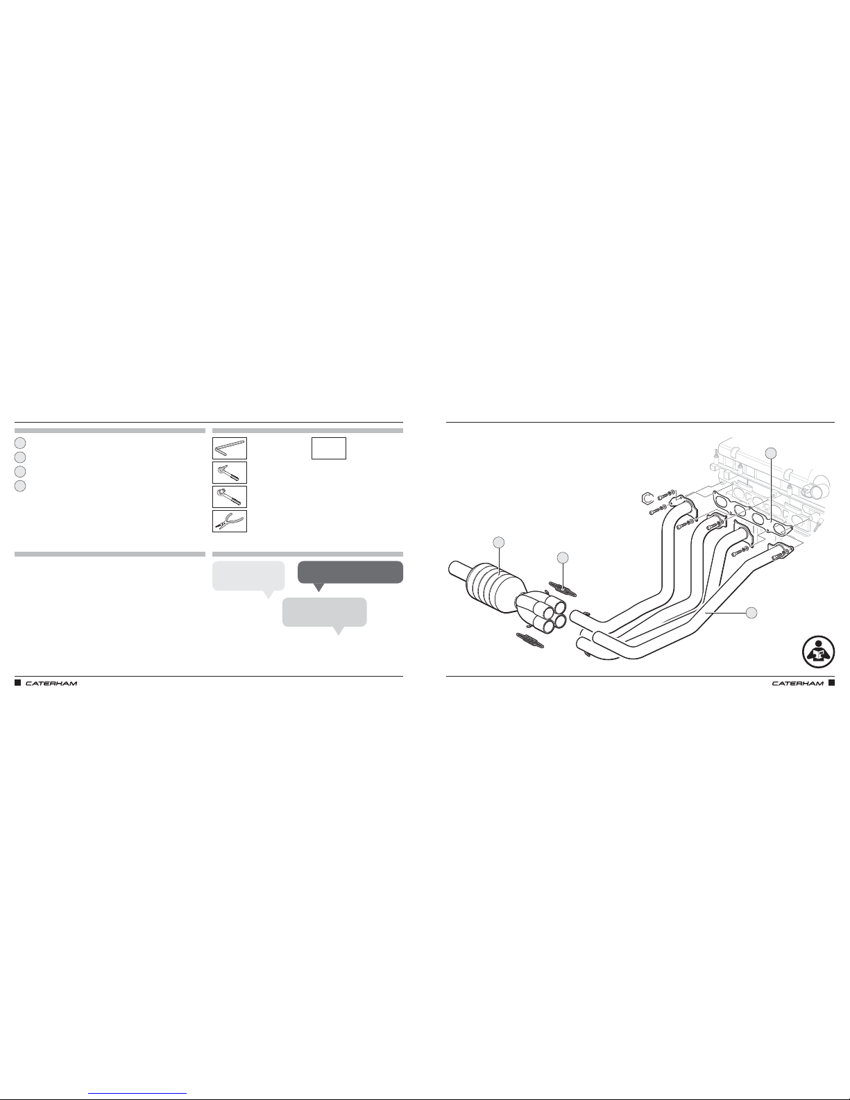
ASSEMBLY GUIDE ASSEMBLY GUIDE
88 89
PARTS TOOLS
THIS IS EXHAUSTING
FIXINGS TIPS
8mm Extension
Exhaust manifold gasket
Cat / Collector
Exhaust primary pipes
Exhaust collector springs
8mm
17mm
(
270
&
310
only)
1
3
2
4
THIS IS EXHAUSTING
Use cable ties to compress
exhaust spring.
Mick F
Put masking tape round exhaust
hole to prevent scratches.
Chris B
A pair of pliers are best to help hook over.
James A
Fixings are supplied loosely attached to the engine in place
2
3
4
1
47Nm
to follow
Page 50
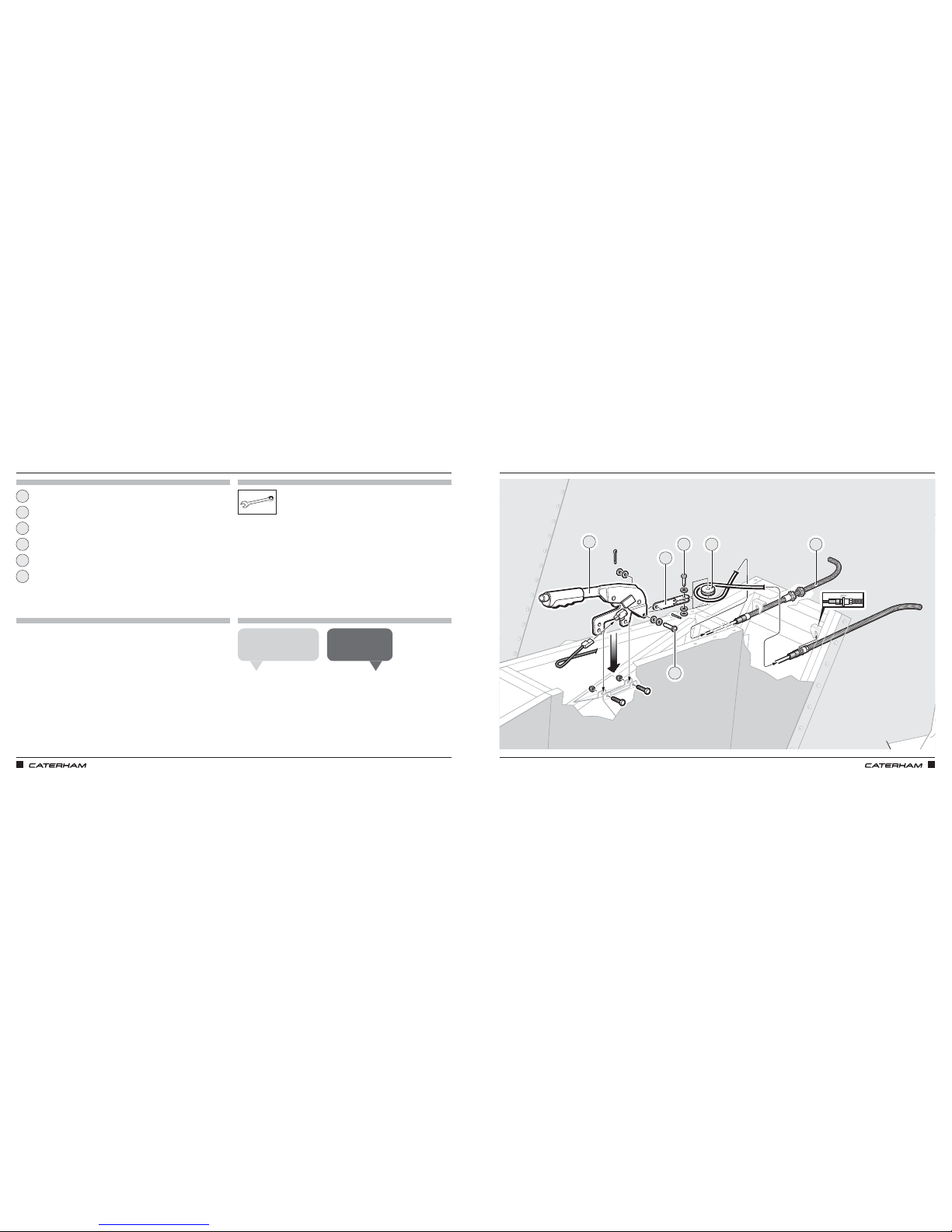
ASSEMBLY GUIDE ASSEMBLY GUIDE
90 91
FITTING THE HANDBRAKEFITTING THE HANDBRAKE
PARTS
FIXINGS
TOOLS
TIPS
13mm (x2)
Handbrake assembly
Handbrake clevis
Handbrake cable
Handbrake pulley
Handbrake clevis pin
Pulley clevis pin
1
3
6
2
5
4
Miscellaneous pack
• Setscrew 8 (x25)
• Washer M8
• Washer M6
Remember to put a loop in
inner cable around pulley.
Grant P
Cable tie adjuster
end of cable to diff.
Dan D
1
3
4 2
5
6
Page 51
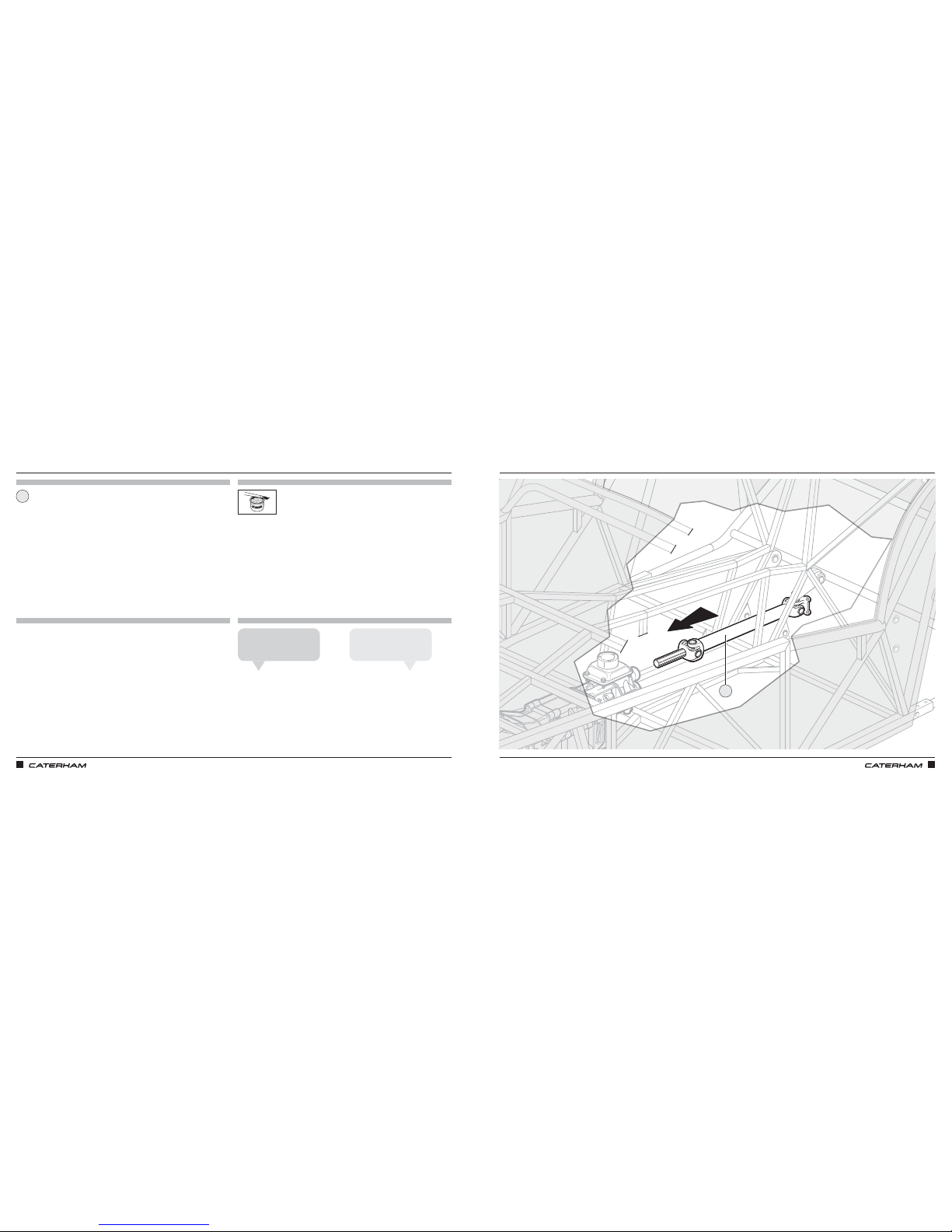
ASSEMBLY GUIDE ASSEMBLY GUIDE
92 93
SLIDE IN THE PROPSHAFTSLIDE IN THE PROPSHAFT
PARTS
FIXINGS
TOOLS
TIPS
Propshaft
1
Line the splines in the
propshaft to the gearbox.
Anthony L
Grease prop if necessary,
it will have a grease nipple.
John S
1
Page 52
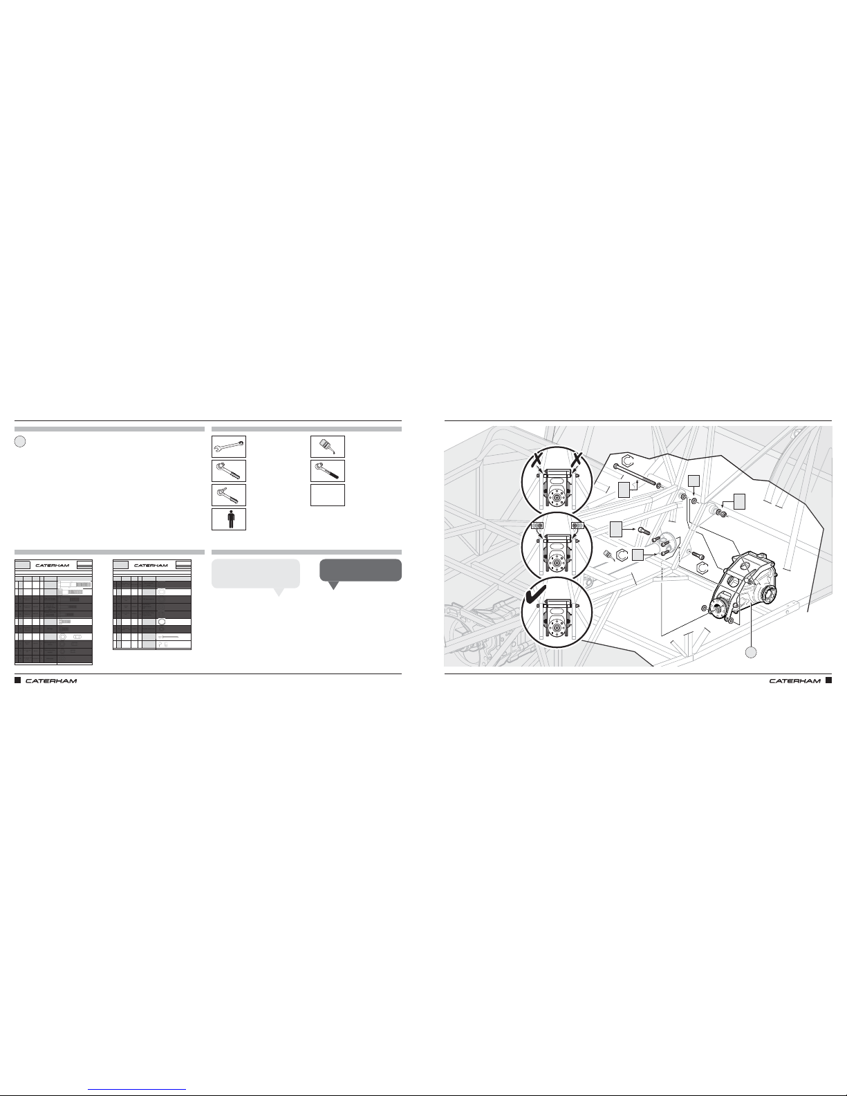
ASSEMBLY GUIDE ASSEMBLY GUIDE
94 95
PART
NUMBER
QTYUSED ON
1IA
BF1/2X11
1
Upper diff mounting
bolt
2IB
BMCH12X55
2
Lower diff mounting
bolt
3IC
BM10X65
4
Rear hub through
ear to front DeDion
4ID
BM10X55
8
x 4 Front hub
through ear
x 4 Caliper carrier
bolts
5IE
BM10X40
4
Through rear of ear
into threaded
DeDion holes
6IF
BMCH10X20
4 Propshaft bolts
7IG
BMCH12X25
2
Diff cage
8IH
NFYH1/21
Upper diff bolt
9II
NMYF10
8
Hub through ear to
DeDion
10 IJ
NMYH8
4
Rear anti roll bar
droplink
11 IK
WPH3/8X7/8
2
Brake pipe
Drawings are for illustrative purposes only and are not to scale.
I
SERIAL
NUMBER
44
Pack
PACK NUMBER
30Z1067B
AXLE DEDION METRIC
This pack may include extra fasteners to cover different options
ITEM
BASIC
DESCRIPTION
ILLUSTRATION
Bolt 1/2" X 11"
UNF
Caphead Bolt
M12 X 65
Grade 10.9
Bolt M10 X 65
Grade 10.9
Bolt M10 X 55
Grade 10.9
Bolt M10 X 40
Grade 10.9
Caphead Bolt
M10 X 20
Grade 12.9
Caphead Bolt
M12 X 25
Grade 8.8
Plain washer 3/8"
X 7/8"
Page 1 of 2
Half Nyloc
1/2" "T" Type
Nyloc Nut
M10
1/2" Nyloc Nut
M8
PART
NUMBER
QTYUSED ON
12 IL
WPT1/2X7/8
16
Fine tuning diff
setup
13 IM
79017
8Free play on diff
14 IN
79029
14 Diff shim washers
15 IO
WPHM10
16
Rear DeDion
Caliper Carrier
Hub
16 IP
WSHM10
16
Rear DeDion Tube
Caliper Carrier
17 IQ 4
Behind bolt heads
on diff
18 IR
WSS3/8
1
Braided brake hose
19 IS
1661-0414 5
P-clips on DeDion
for brake pipe
20 IT
NX1
5
Brake pipe on
DeDion
Drawings are for illustrative purposes only and are not to scale.
Schnorr washer
M12
Shakeproof
washer 3/8"
Plain washer 1/2"
X 3/4" Thin
Plain washer
1/2"
X 3/4" X 17G
Thick
Washer
M10
Spring Washer
M10
Page 2 of 2
Rivet
1/8" X 0.51"
P-Clip
AXLE DEDION METRIC
This pack may include extra fasteners to cover different options
ITEM
BASIC
DESCRIPTION
ILLUSTRATION
Plain washer 1/2"
X 7/8" Thin
I
SERIAL
NUMBER
44
Pack
PACK NUMBER
30Z1067B
PARTS
FIXINGS
TOOLS
TIPS
x1
x2
x4
x1
19mm
Dierential
19mm
10mm
8mm
x4
1
HEAVY STUFF: FITTING THE DIFFHEAVY STUFF: FITTING THE DIFF
Start at bottom right with
spanner & work your way around.
Chris B
Make sure propshaft is in first!
Harry P
1
IM
IA
IQ
IH
IQ
IB
IQ
IF
Extension
LOCTITE
LOCTITE
LOCTITE
LOCTITE
61Nm
47Nm
47Nm
+
to follow
* Use as required for spacing
*
Page 53
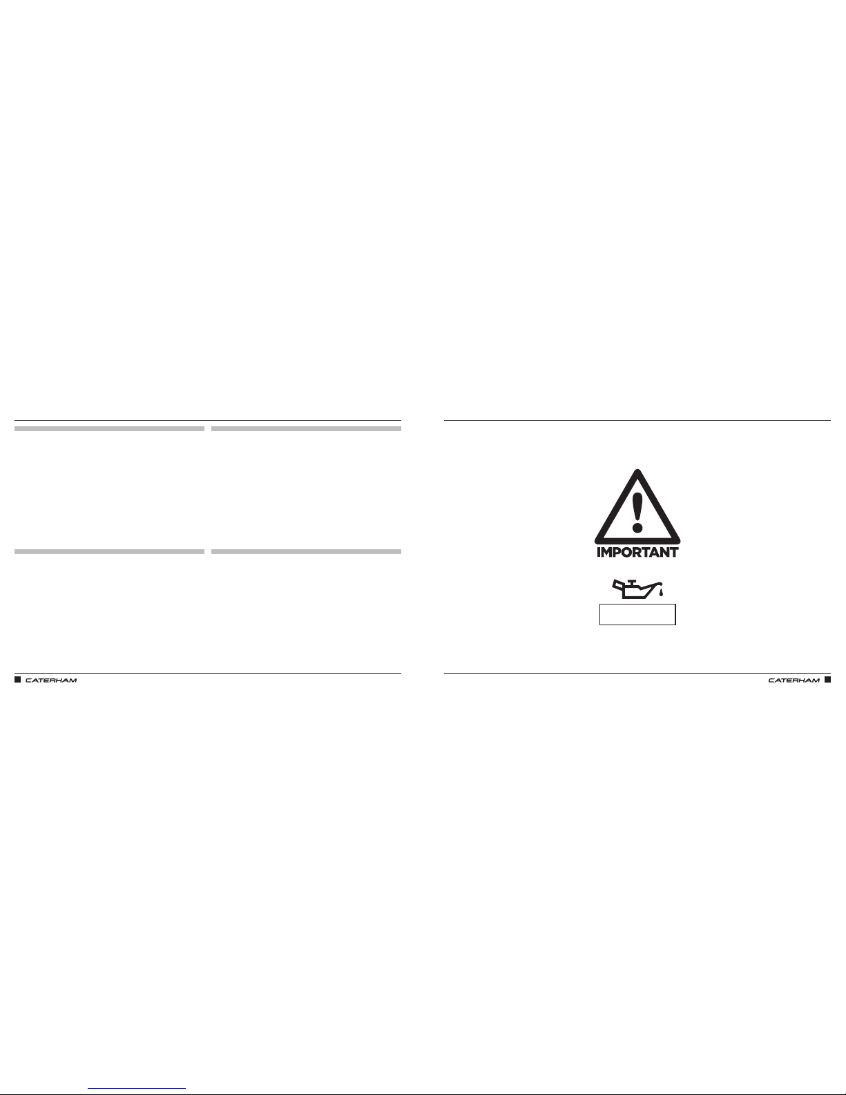
ASSEMBLY GUIDE ASSEMBLY GUIDE
96 97
PARTS
FIXINGS
TOOLS
TIPS
Dierential oil
FILL THE DIFFERENTIAL WITH OILFILL THE DIFFERENTIAL WITH OIL
Dierential = 0.8L
Page 54
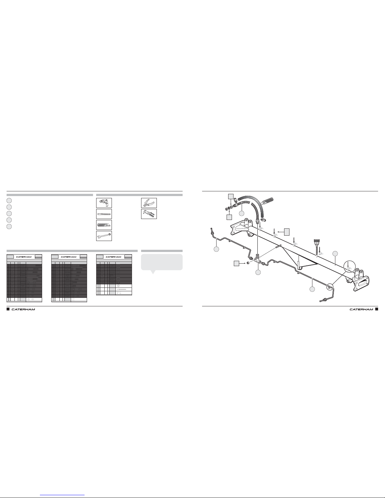
ASSEMBLY GUIDE ASSEMBLY GUIDE
98 99
PART
NUMBER
QTYUSED ON
1IA
BF1/2X11
1
Upper diff mounting
bolt
2IB
BMCH12X55
2
Lower diff mounting
bolt
3IC
BM10X65
4
Rear hub through
ear to front DeDion
4ID
BM10X55
8
x 4 Front hub
through ear
x 4 Caliper carrier
bolts
5IE
BM10X40
4
Through rear of ear
into threaded
DeDion holes
6IF
BMCH10X20
4 Propshaft bolts
7IG
BMCH12X25
2
Diff cage
8IH
NFYH1/21
Upper diff bolt
9II
NMYF10
8
Hub through ear to
DeDion
10 IJ
NMYH8
4
Rear anti roll bar
droplink
11 IK
WPH3/8X7/8
2
Brake pipe
Drawings are for illustrative purposes only and are not to scale.
I
SERIAL
NUMBER
44
Pack
PACK NUMBER
30Z1067B
AXLE DEDION METRIC
This pack may include extra fasteners to cover different options
ITEM
BASIC
DESCRIPTION
ILLUSTRATION
Bolt 1/2" X 11"
UNF
Caphead Bolt
M12 X 65
Grade 10.9
Bolt M10 X 65
Grade 10.9
Bolt M10 X 55
Grade 10.9
Bolt M10 X 40
Grade 10.9
Caphead Bolt
M10 X 20
Grade 12.9
Caphead Bolt
M12 X 25
Grade 8.8
Plain washer 3/8"
X 7/8"
Page 1 of 2
Half Nyloc
1/2" "T" Type
Nyloc Nut
M10
1/2" Nyloc Nut
M8
PART
NUMBER
QTYUSED ON
12 IL
WPT1/2X7/8
16
Fine tuning diff
setup
13 IM
79017
8Free play on diff
14 IN
79029
14 Diff shim washers
15 IO
WPHM10
16
Rear DeDion
Caliper Carrier
Hub
16 IP
WSHM10
16
Rear DeDion Tube
Caliper Carrier
17 IQ 4
Behind bolt heads
on diff
18 IR
WSS3/8
1
Braided brake hose
19 IS
1661-0414 5
P-clips on DeDion
for brake pipe
20 IT
NX1
5
Brake pipe on
DeDion
Drawings are for illustrative purposes only and are not to scale.
Schnorr washer
M12
Shakeproof
washer 3/8"
Plain washer 1/2"
X 3/4" Thin
Plain washer
1/2"
X 3/4" X 17G
Thick
Washer
M10
Spring Washer
M10
Page 2 of 2
Rivet
1/8" X 0.51"
P-Clip
AXLE DEDION METRIC
This pack may include extra fasteners to cover different options
ITEM
BASIC
DESCRIPTION
ILLUSTRATION
Plain washer 1/2"
X 7/8" Thin
I
SERIAL
NUMBER
44
Pack
PACK NUMBER
30Z1067B
PREPARING THE DEDION TUBEPREPARING THE DEDION TUBE
PARTS
FIXINGS
TOOLS
TIPS
DeDion tube
RHS brake pipe
LHS brake pipe
Brake hose
3 way union
⅛"
1
3
2
5
4
5
4
2
3
1
5 x ⅛"
HK
IS
IT
11mm
13mm
14mm
The upper brake hose fittings will
become self explanatory on the rear
damper installation page.
John K
PART
NUMBER
QTYUSED ON
1HA
BM12X100
2
A-frame fromt
mountings
2HB
BMCH10X65
2
Front radius arm
(through cockpit)
3HC
BF1/2X2.1/2
4
x 2 Lower Rear
Damper x
2 Rear Radius Arm
4HD
BM6X80
4
Rear Anti Roll Bar
Mounting Blocks
5HE
BF1/2X2.3/4
1 A-frame to DeDion
6HF
NFYH1/2
3
x 2 Rear Radius
Arm x
1 A-frame to DeDion
7HG
NMYF12
2
A-frame front
mounts
8HH
NMYF10 2
Front radius arm
(through cockpit)
9HI
NMYH8
2
Rear Anti Roll Bar
Drop Link
10 HJ
NMYF6
4
Rear Anti Roll Bar
Mounting Blocks
11 HK
NFYF1/4
1
3 - way union on
DeDion tube
Drawings are for illustrative purposes only and are not to scale.
Nyloc Nut 1/4"
Page 1 of 2
Nyloc Nut
M10
Half Nyloc
M8
Nyloc Nut
M6
Bolt 1/2" X 2.3/4"
Grade 10.9
Half Nyloc
1/2" UNF
Nyloc Nut
M12
Caphead Bolt
M10 X 65
Bolt
1/2" X 2.1/2"
Grade 10.9
Bolt M6 X 80
Grade 10.9
REAR SUSPENSION DEDION METRIC
This pack may include extra fasteners to cover different options
ITEM
BASIC
DESCRIPTION
ILLUSTRATION
Bolt M12 X 100
Grade 10.9
H
SERIAL
NUMBER
53
Pack
PACK NUMBER
30R011D
x1
IR
IK
x2
x1
x5
x5
Brake pipe washers and nuts are included with
the hose
Page 55
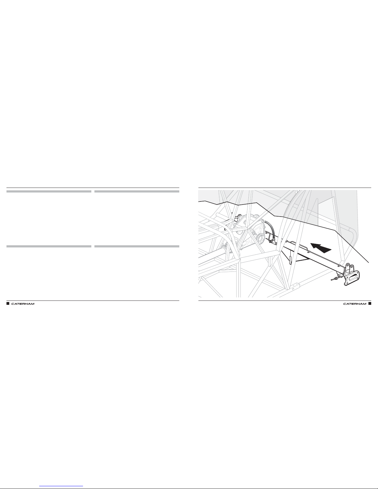
ASSEMBLY GUIDE ASSEMBLY GUIDE
100 101
AND FITTING IT IN PLACEAND FITTING IT IN PLACE
PARTS
FIXINGS
TOOLS
TIPS
Page 56
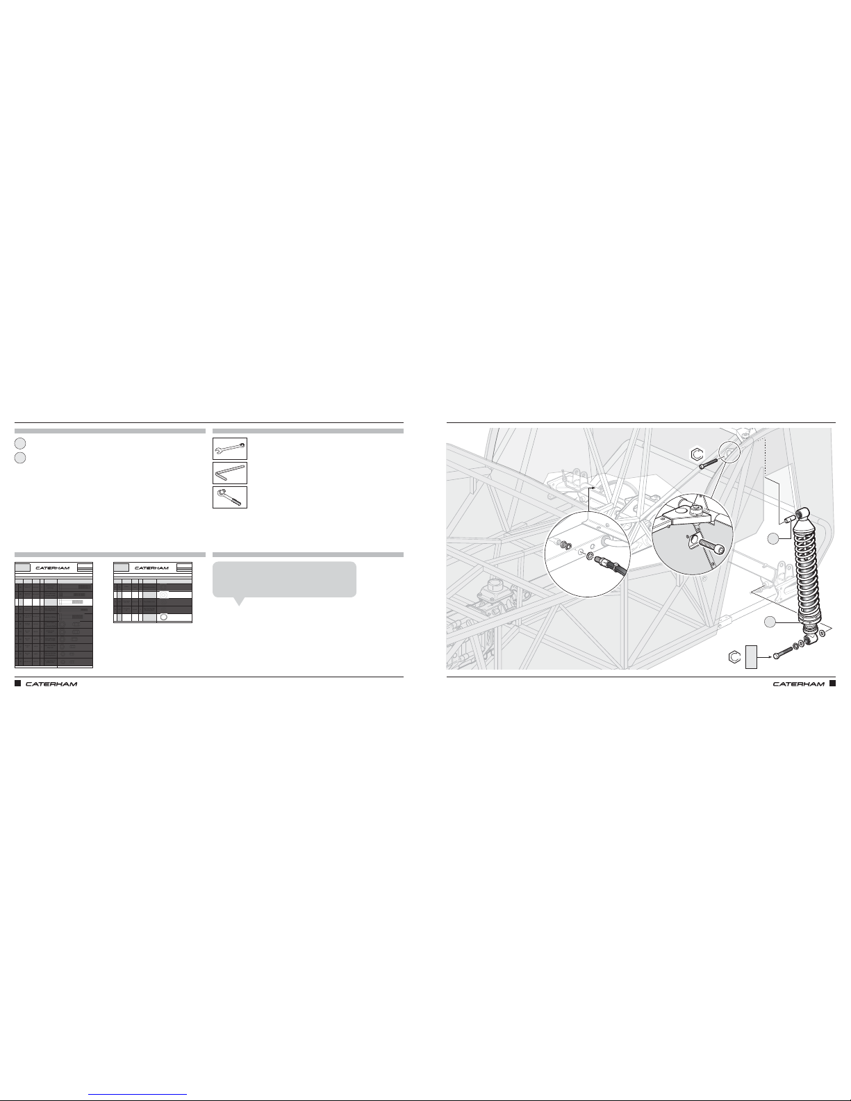
ASSEMBLY GUIDE ASSEMBLY GUIDE
102 103
PART
NUMBER
QTYUSED ON
1HA
BM12X100
2
A-frame fromt
mountings
2HB
BMCH10X65
2
Front radius arm
(through cockpit)
3HC
BF1/2X2.1/2
4
x 2 Lower Rear
Damper x
2 Rear Radius Arm
4HD
BM6X80
4
Rear Anti Roll Bar
Mounting Blocks
5HE
BF1/2X2.3/4
1 A-frame to DeDion
6HF
NFYH1/2
3
x 2 Rear Radius
Arm x
1 A-frame to DeDion
7HG
NMYF12
2
A-frame front
mounts
8HH
NMYF10 2
Front radius arm
(through cockpit)
9HI
NMYH8
2
Rear Anti Roll Bar
Drop Link
10 HJ
NMYF6
4
Rear Anti Roll Bar
Mounting Blocks
11 HK
NFYF1/4
1
3 - way union on
DeDion tube
Drawings are for illustrative purposes only and are not to scale.
Nyloc Nut 1/4"
Page 1 of 2
Nyloc Nut
M10
Half Nyloc
M8
Nyloc Nut
M6
Bolt 1/2" X 2.3/4"
Grade 10.9
Half Nyloc
1/2" UNF
Nyloc Nut
M12
Caphead Bolt
M10 X 65
Bolt
1/2" X 2.1/2"
Grade 10.9
Bolt M6 X 80
Grade 10.9
REAR SUSPENSION DEDION METRIC
This pack may include extra fasteners to cover different options
ITEM
BASIC
DESCRIPTION
ILLUSTRATION
Bolt M12 X 100
Grade 10.9
H
SERIAL
NUMBER
53
Pack
PACK NUMBER
30R011D
ATTACHING THE REAR DAMPERSATTACHING THE REAR DAMPERS
PARTS
FIXINGS
TOOLS
TIPS
PART
NUMBER
QTYUSED ON
12 HL
79029
10 Differential Isolation
13 HM
WPH1/2
20
x 2 Lower Damper
x 10 A-frame
washers x
4 Radius Arm
14 HN
WPH3/8X7/8
2Front Radius Arm
15 HO
WPHM6
4
Rear Anti Roll Bar
Mounting Block
16 HP
30Z1069A
2 Lower Damper
Drawings are for illustrative purposes only and are not to scale.
H
SERIAL
NUMBER
53
Pack
PACK NUMBER
30R011D
REAR SUSPENSION DEDION METRIC
This pack may include extra fasteners to cover different options
ITEM
BASIC
DESCRIPTION
ILLUSTRATION
Washer
Page 2 of 2
Schnorr Washer
M12
Plain Washer
1/2" Chamferred
Plain Washer
3/8" X 7/8"
Plain Washer
M6
x2
Rear damper assembly
Rear damper sleeve
x4
x2
1
2
2
1
HC
HM
HP
13mm
14mm
8mm
19mm
47Nm
81Nm
Although we show the fitting of the dampers here as part
of the rear suspension, it is better to leave this step until
you've fitted the roll over bar much later in the process.
Jamie A
Page 57
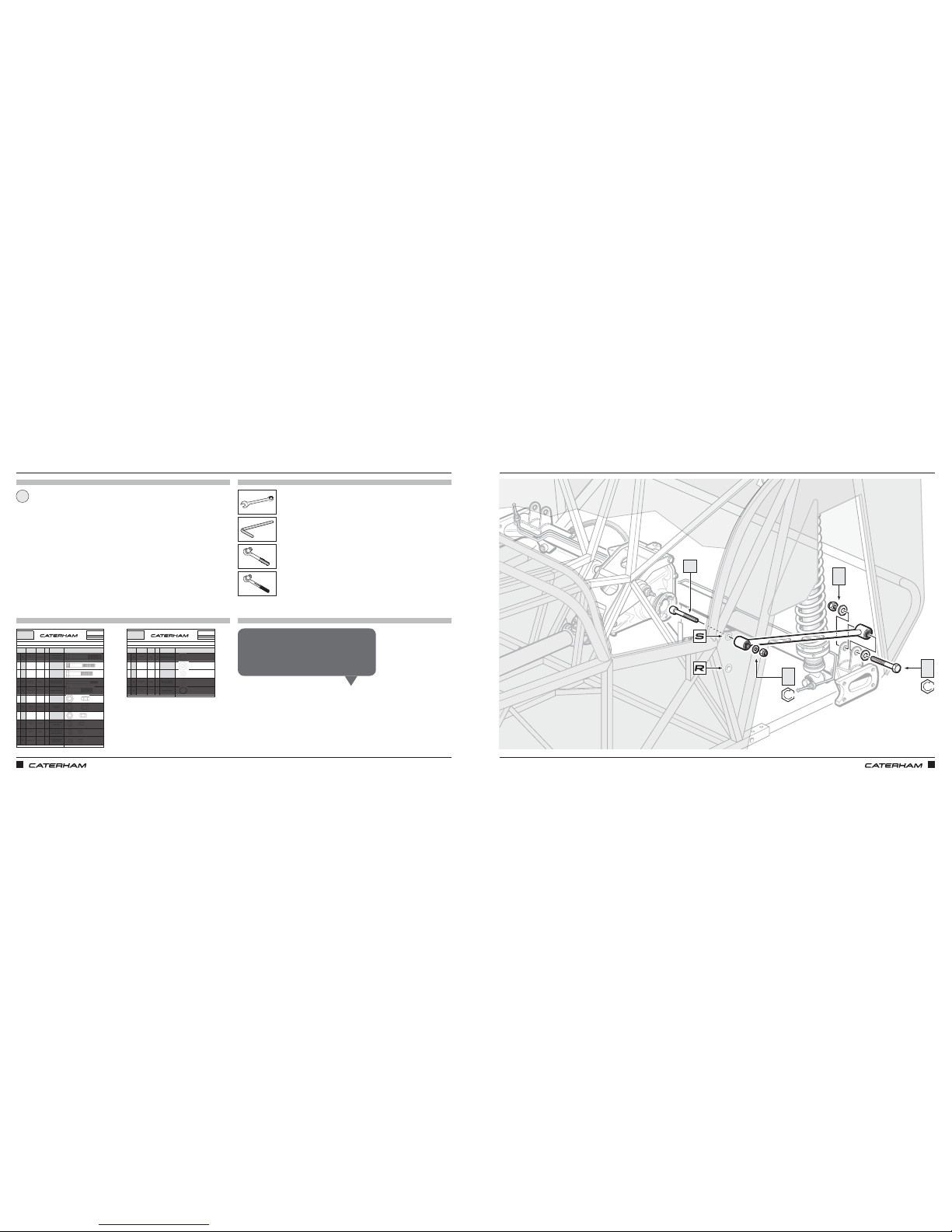
ASSEMBLY GUIDE ASSEMBLY GUIDE
104 105
PART
NUMBER
QTYUSED ON
1HA
BM12X100
2
A-frame fromt
mountings
2HB
BMCH10X65
2
Front radius arm
(through cockpit)
3HC
BF1/2X2.1/2
4
x 2 Lower Rear
Damper x
2 Rear Radius Arm
4HD
BM6X80
4
Rear Anti Roll Bar
Mounting Blocks
5HE
BF1/2X2.3/4
1 A-frame to DeDion
6HF
NFYH1/2
3
x 2 Rear Radius
Arm x
1 A-frame to DeDion
7HG
NMYF12
2
A-frame front
mounts
8HH
NMYF10 2
Front radius arm
(through cockpit)
9HI
NMYH8
2
Rear Anti Roll Bar
Drop Link
10 HJ
NMYF6
4
Rear Anti Roll Bar
Mounting Blocks
11 HK
NFYF1/4
1
3 - way union on
DeDion tube
Drawings are for illustrative purposes only and are not to scale.
Nyloc Nut 1/4"
Page 1 of 2
Nyloc Nut
M10
Half Nyloc
M8
Nyloc Nut
M6
Bolt 1/2" X 2.3/4"
Grade 10.9
Half Nyloc
1/2" UNF
Nyloc Nut
M12
Caphead Bolt
M10 X 65
Bolt
1/2" X 2.1/2"
Grade 10.9
Bolt M6 X 80
Grade 10.9
REAR SUSPENSION DEDION METRIC
This pack may include extra fasteners to cover different options
ITEM
BASIC
DESCRIPTION
ILLUSTRATION
Bolt M12 X 100
Grade 10.9
H
SERIAL
NUMBER
53
Pack
PACK NUMBER
30R011D
PART
NUMBER
QTYUSED ON
12 HL
79029
10 Differential Isolation
13 HM
WPH1/2
20
x 2 Lower Damper
x 10 A-frame
washers x
4 Radius Arm
14 HN
WPH3/8X7/8
2Front Radius Arm
15 HO
WPHM6
4
Rear Anti Roll Bar
Mounting Block
16 HP
30Z1069A
2 Lower Damper
Drawings are for illustrative purposes only and are not to scale.
H
SERIAL
NUMBER
53
Pack
PACK NUMBER
30R011D
REAR SUSPENSION DEDION METRIC
This pack may include extra fasteners to cover different options
ITEM
BASIC
DESCRIPTION
ILLUSTRATION
Washer
Page 2 of 2
Schnorr Washer
M12
Plain Washer
1/2" Chamferred
Plain Washer
3/8" X 7/8"
Plain Washer
M6
PARTS
FIXINGS
TOOLS
TIPS
Radius arm
1
THEN THE RADIUS ARMTHEN THE RADIUS ARM
x2
x2
x2
x2
x4
x2
HF
HM
HC
HM
HH
HN
HB
19mm
8mm
17mm
19mm
Before torquing up these bolts, reposition the
axle stands to under the DeDion tube (to hold up
the suspension). Make sure front has two axle
stands so it is steady when jacking up the rear!
Mick F
81Nm
34Nm
Page 58
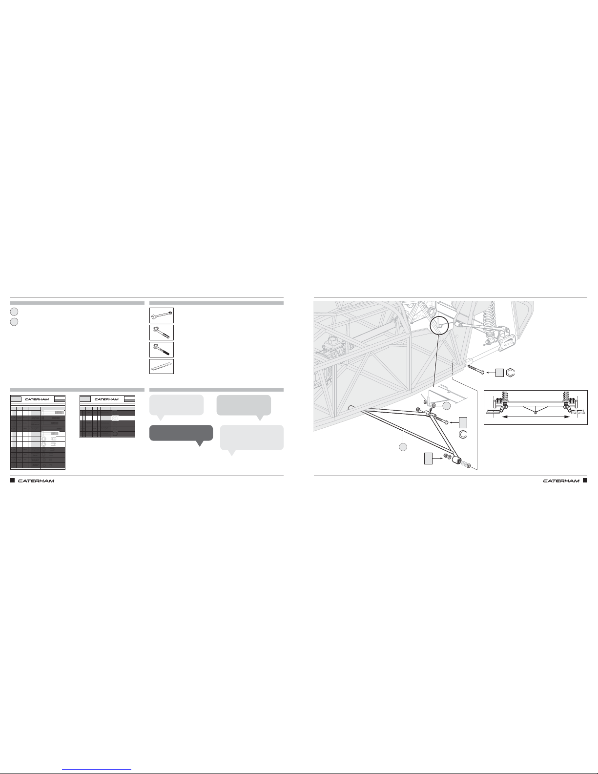
ASSEMBLY GUIDE ASSEMBLY GUIDE
106 107
PART
NUMBER
QTYUSED ON
1HA
BM12X100
2
A-frame fromt
mountings
2HB
BMCH10X65
2
Front radius arm
(through cockpit)
3HC
BF1/2X2.1/2
4
x 2 Lower Rear
Damper x
2 Rear Radius Arm
4HD
BM6X80
4
Rear Anti Roll Bar
Mounting Blocks
5HE
BF1/2X2.3/4
1 A-frame to DeDion
6HF
NFYH1/2
3
x 2 Rear Radius
Arm x
1 A-frame to DeDion
7HG
NMYF12
2
A-frame front
mounts
8HH
NMYF10 2
Front radius arm
(through cockpit)
9HI
NMYH8
2
Rear Anti Roll Bar
Drop Link
10 HJ
NMYF6
4
Rear Anti Roll Bar
Mounting Blocks
11 HK
NFYF1/4
1
3 - way union on
DeDion tube
Drawings are for illustrative purposes only and are not to scale.
Nyloc Nut 1/4"
Page 1 of 2
Nyloc Nut
M10
Half Nyloc
M8
Nyloc Nut
M6
Bolt 1/2" X 2.3/4"
Grade 10.9
Half Nyloc
1/2" UNF
Nyloc Nut
M12
Caphead Bolt
M10 X 65
Bolt
1/2" X 2.1/2"
Grade 10.9
Bolt M6 X 80
Grade 10.9
REAR SUSPENSION DEDION METRIC
This pack may include extra fasteners to cover different options
ITEM
BASIC
DESCRIPTION
ILLUSTRATION
Bolt M12 X 100
Grade 10.9
H
SERIAL
NUMBER
53
Pack
PACK NUMBER
30R011D
PART
NUMBER
QTYUSED ON
12 HL
79029
10 Differential Isolation
13 HM
WPH1/2
20
x 2 Lower Damper
x 10 A-frame
washers x
4 Radius Arm
14 HN
WPH3/8X7/8
2Front Radius Arm
15 HO
WPHM6
4
Rear Anti Roll Bar
Mounting Block
16 HP
30Z1069A
2 Lower Damper
Drawings are for illustrative purposes only and are not to scale.
H
SERIAL
NUMBER
53
Pack
PACK NUMBER
30R011D
REAR SUSPENSION DEDION METRIC
This pack may include extra fasteners to cover different options
ITEM
BASIC
DESCRIPTION
ILLUSTRATION
Washer
Page 2 of 2
Schnorr Washer
M12
Plain Washer
1/2" Chamferred
Plain Washer
3/8" X 7/8"
Plain Washer
M6
AND NOW THE (CAREFULLY SPACED) A-FRAMEAND NOW THE (CAREFULLY SPACED) A-FRAME
PARTS
FIXINGS
TOOLS
TIPS
A-frame
1
x2
x1
x1
x2
Use as many HM washers as
required to space A‑frame.
John K
Take care to use the correct nuts
as there is a mixture of metric and
imperial here.
Lee A
Torque up as before on axle stands.
Rich T
1
HM
HG
HE
HF
HA
==
Make sure the DeDion tube
is equal on both sides.
Tiago O
White nylon anti-squeak washers
2
19mm
19mm (x2)
2
81Nm
81Nm
* Use as required for spacing
*
Page 59
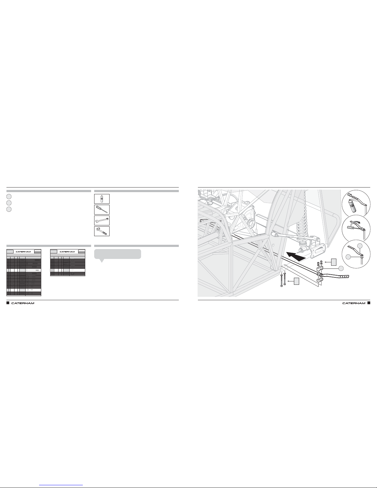
ASSEMBLY GUIDE ASSEMBLY GUIDE
108 109
PART
NUMBER
QTYUSED ON
1HA
BM12X100
2
A-frame fromt
mountings
2HB
BMCH10X65
2
Front radius arm
(through cockpit)
3HC
BF1/2X2.1/2
4
x 2 Lower Rear
Damper x
2 Rear Radius Arm
4HD
BM6X80
4
Rear Anti Roll Bar
Mounting Blocks
5HE
BF1/2X2.3/4
1 A-frame to DeDion
6HF
NFYH1/2
3
x 2 Rear Radius
Arm x
1 A-frame to DeDion
7HG
NMYF12
2
A-frame front
mounts
8HH
NMYF10 2
Front radius arm
(through cockpit)
9HI
NMYH8
2
Rear Anti Roll Bar
Drop Link
10 HJ
NMYF6
4
Rear Anti Roll Bar
Mounting Blocks
11 HK
NFYF1/4
1
3 - way union on
DeDion tube
Drawings are for illustrative purposes only and are not to scale.
Nyloc Nut 1/4"
Page 1 of 2
Nyloc Nut
M10
Half Nyloc
M8
Nyloc Nut
M6
Bolt 1/2" X 2.3/4"
Grade 10.9
Half Nyloc
1/2" UNF
Nyloc Nut
M12
Caphead Bolt
M10 X 65
Bolt
1/2" X 2.1/2"
Grade 10.9
Bolt M6 X 80
Grade 10.9
REAR SUSPENSION DEDION METRIC
This pack may include extra fasteners to cover different options
ITEM
BASIC
DESCRIPTION
ILLUSTRATION
Bolt M12 X 100
Grade 10.9
H
SERIAL
NUMBER
53
Pack
PACK NUMBER
30R011D
PART
NUMBER
QTYUSED ON
12 HL
79029
10 Differential Isolation
13 HM
WPH1/2
20
x 2 Lower Damper
x 10 A-frame
washers x
4 Radius Arm
14 HN
WPH3/8X7/8
2Front Radius Arm
15 HO
WPHM6
4
Rear Anti Roll Bar
Mounting Block
16 HP
30Z1069A
2 Lower Damper
Drawings are for illustrative purposes only and are not to scale.
H
SERIAL
NUMBER
53
Pack
PACK NUMBER
30R011D
REAR SUSPENSION DEDION METRIC
This pack may include extra fasteners to cover different options
ITEM
BASIC
DESCRIPTION
ILLUSTRATION
Washer
Page 2 of 2
Schnorr Washer
M12
Plain Washer
1/2" Chamferred
Plain Washer
3/8" X 7/8"
Plain Washer
M6
IF YOU HAVE THE OPTIONAL REAR ANTI-ROLL BAR, IT GOES ON LIKE THISIF YOU HAVE THE OPTIONAL REAR ANTI-ROLL BAR, IT GOES ON LIKE THIS
PARTS
FIXINGS
TOOLS
TIPS
x4
x4
Rear anti roll bar
Rear anti roll bar clamp
Anti roll bar rubber
x8
1
3
2
HJ
HO
HD
HO
2
1
3
10mm
10mm
Be careful not to slip with the screwdriver!
John S
Page 60
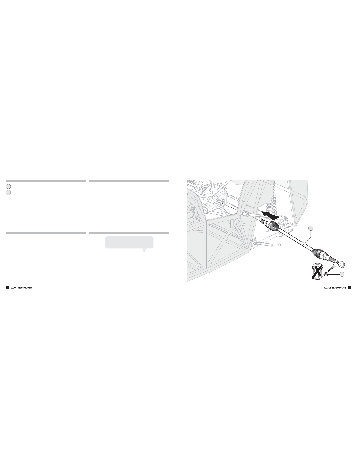
ASSEMBLY GUIDE ASSEMBLY GUIDE
110 111
PARTS
FIXINGS
TOOLS
TIPS
Driveshaft
Driveshaft nut
1
2
INSERT THE DRIVESHAFTSINSERT THE DRIVESHAFTS
2
1
Driveshafts are handed, and so are the nuts,
the left hand nut tightens anti‑clockwise.
James A
Page 61
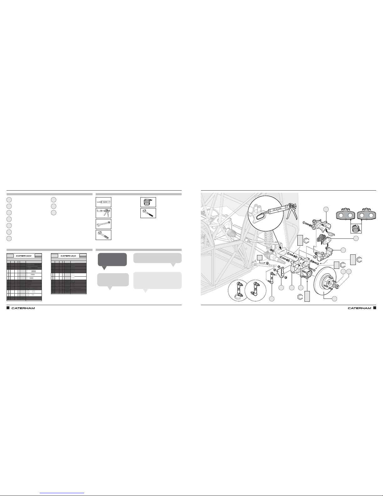
ASSEMBLY GUIDE ASSEMBLY GUIDE
112 113
PART
NUMBER
QTYUSED ON
1IA
BF1/2X11
1
Upper diff mounting
bolt
2IB
BMCH12X55
2
Lower diff mounting
bolt
3IC
BM10X65
4
Rear hub through
ear to front DeDion
4ID
BM10X55
8
x 4 Front hub
through ear
x 4 Caliper carrier
bolts
5IE
BM10X40
4
Through rear of ear
into threaded
DeDion holes
6IF
BMCH10X20
4 Propshaft bolts
7IG
BMCH12X25
2
Diff cage
8IH
NFYH1/21
Upper diff bolt
9II
NMYF10
8
Hub through ear to
DeDion
10 IJ
NMYH8
4
Rear anti roll bar
droplink
11 IK
WPH3/8X7/8
2
Brake pipe
Drawings are for illustrative purposes only and are not to scale.
I
SERIAL
NUMBER
44
Pack
PACK NUMBER
30Z1067B
AXLE DEDION METRIC
This pack may include extra fasteners to cover different options
ITEM
BASIC
DESCRIPTION
ILLUSTRATION
Bolt 1/2" X 11"
UNF
Caphead Bolt
M12 X 65
Grade 10.9
Bolt M10 X 65
Grade 10.9
Bolt M10 X 55
Grade 10.9
Bolt M10 X 40
Grade 10.9
Caphead Bolt
M10 X 20
Grade 12.9
Caphead Bolt
M12 X 25
Grade 8.8
Plain washer 3/8"
X 7/8"
Page 1 of 2
Half Nyloc
1/2" "T" Type
Nyloc Nut
M10
1/2" Nyloc Nut
M8
PART
NUMBER
QTYUSED ON
12 IL
WPT1/2X7/8
16
Fine tuning diff
setup
13 IM
79017
8Free play on diff
14 IN
79029
14 Diff shim washers
15 IO
WPHM10
16
Rear DeDion
Caliper Carrier
Hub
16 IP
WSHM10
16
Rear DeDion Tube
Caliper Carrier
17 IQ 4
Behind bolt heads
on diff
18 IR
WSS3/8
1
Braided brake hose
19 IS
1661-0414 5
P-clips on DeDion
for brake pipe
20 IT
NX1
5
Brake pipe on
DeDion
Drawings are for illustrative purposes only and are not to scale.
Schnorr washer
M12
Shakeproof
washer 3/8"
Plain washer 1/2"
X 3/4" Thin
Plain washer
1/2"
X 3/4" X 17G
Thick
Washer
M10
Spring Washer
M10
Page 2 of 2
Rivet
1/8" X 0.51"
P-Clip
AXLE DEDION METRIC
This pack may include extra fasteners to cover different options
ITEM
BASIC
DESCRIPTION
ILLUSTRATION
Plain washer 1/2"
X 7/8" Thin
I
SERIAL
NUMBER
44
Pack
PACK NUMBER
30Z1067B
FITTING THE REAR HUBFITTING THE REAR HUB
PARTS
FIXINGS
TOOLS
TIPS
Rear brake disc / flange assembly Brake pads
DeDion ear Driveshaft washer
Brake calliper
Rear hub Driveshaft nut
Anti roll bar drop link
Anti roll bar bracket
Brake calliper mount
12mm
13mm
15mm
17mm (x2)
1 8
3 10
6
2 9
5
4
7
Swap the plain nuts on
the droplinks for nylons.
Chris B
Torque up the bearing and
ear before fitting the disc.
Dan D
Remember the driveshaft nuts are handed.
Grant P
If you don't have an anti roll bar you will
only have one bracket (for the right hand
side) which holds the speed sensor.
Rich T
ID
IO
II
5
4 3 2
1
7
8
10 9
IC
II
IE
IO
IP
IJ
ID
IO
IP
6
17mm
x4
x8
x4
x8
x4
x16
x8
47Nm
47Nm
47Nm
47Nm
Page 62
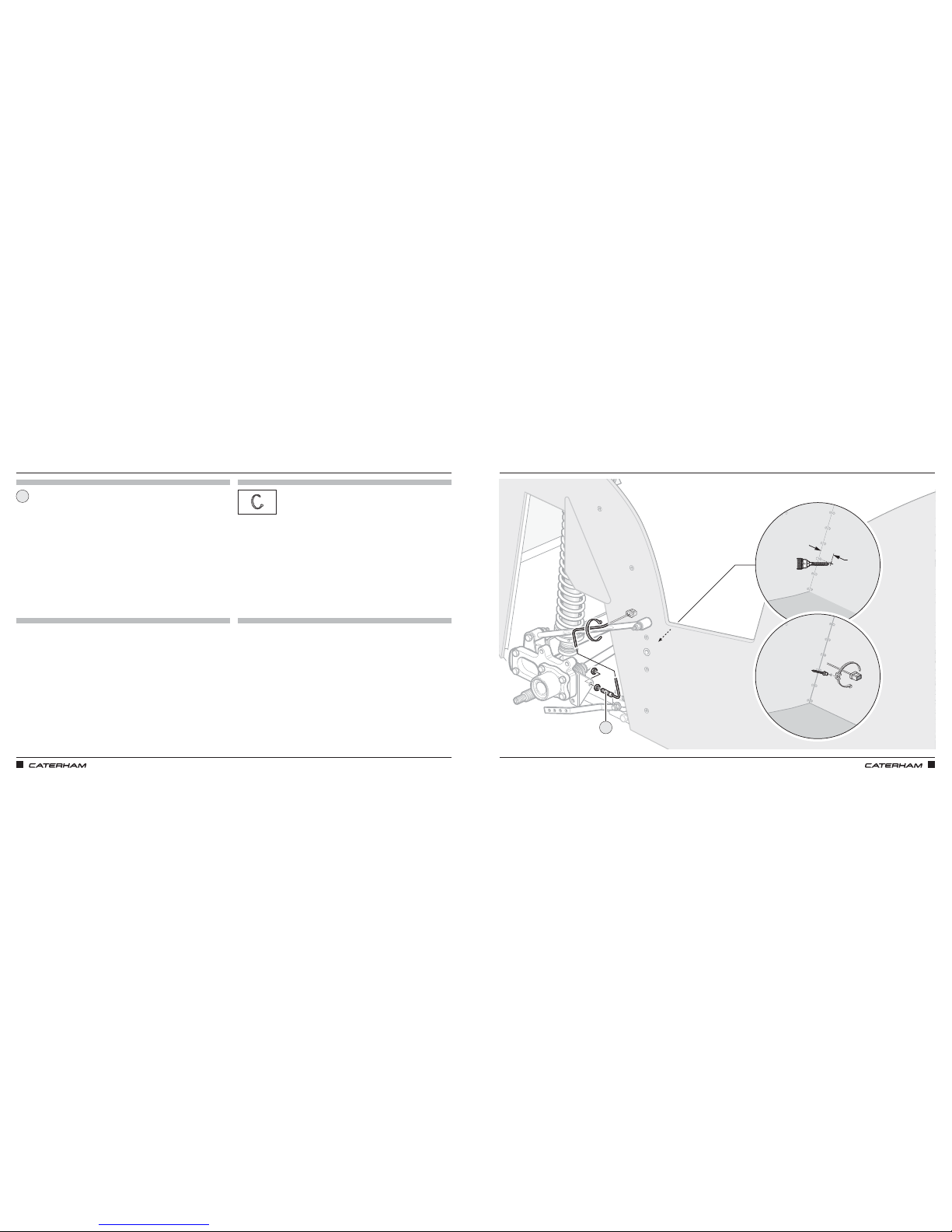
ASSEMBLY GUIDE ASSEMBLY GUIDE
114 115
7
7
30mm
1 x ⁄"
AND SPEED SENSOR (ONE SIDE ONLY)AND SPEED SENSOR (ONE SIDE ONLY)
PARTS
FIXINGS
TOOLS
TIPS
Speed sensor
1
1
Page 63

ASSEMBLY GUIDE ASSEMBLY GUIDE
116 117
Now is a good time to take some photos Have you applied for your IVA yet?
Page 64
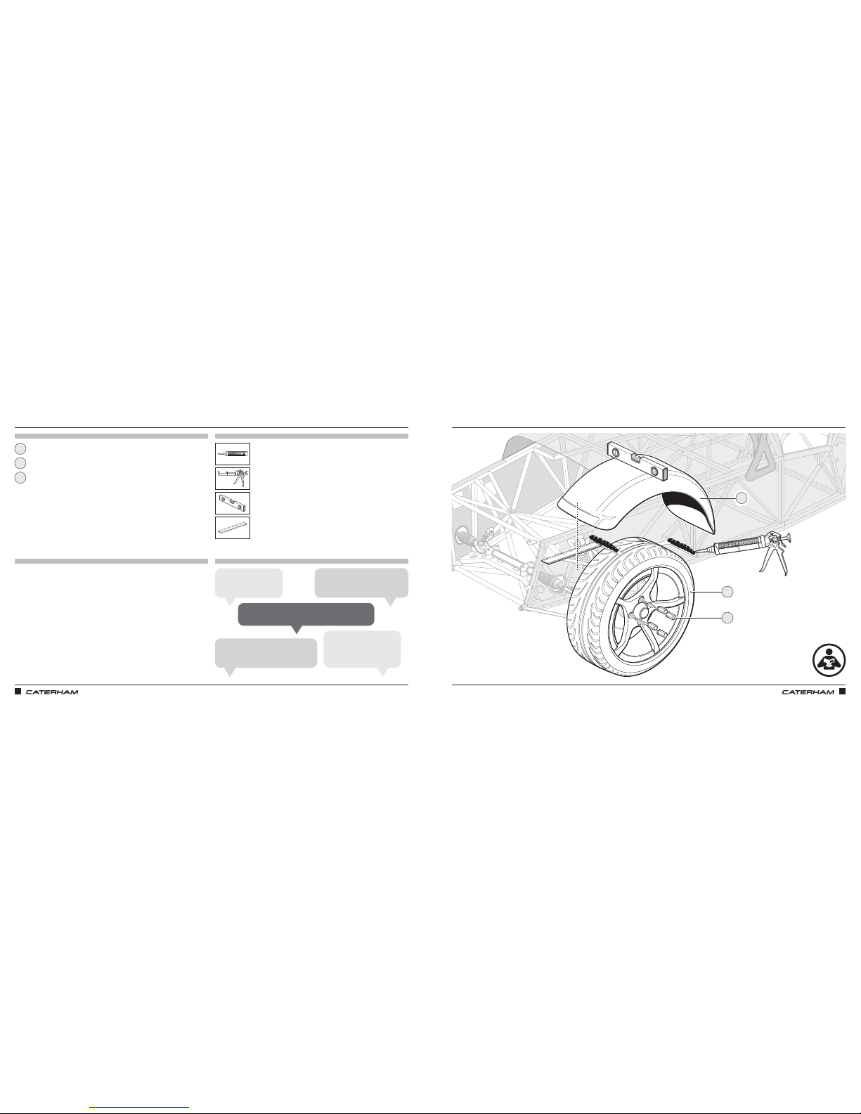
ASSEMBLY GUIDE ASSEMBLY GUIDE
118 119
JUST WING IT
PARTS
FIXINGS
TOOLS
TIPS
Cycle wing
Wheel nuts
Wheel
1
3
2
JUST WING IT
You may need to bend the arms of
the wingstay to make the wing level.
Anthony L
The distance from the front edge of the
wing to the wingstay should be 80mm.
Lee A
Do a 'dry run' first to make
sure the wings are level
before using power adhesive.
Chris N
Key the wing & wingstay
before using adhesive.
John S
The 1⁄8" hole you drilled earlier is for the indicator earth.
Harry P
3
2
1
Page 65
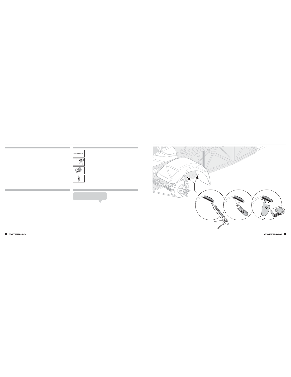
ASSEMBLY GUIDE ASSEMBLY GUIDE
120 121
SOME EXTRA ADHESIVE UNDERNEATH
PARTS
FIXINGS
TOOLS
TIPS
JUST WING IT
The WD40 will help spread the adhesive.
Mick F
Page 66
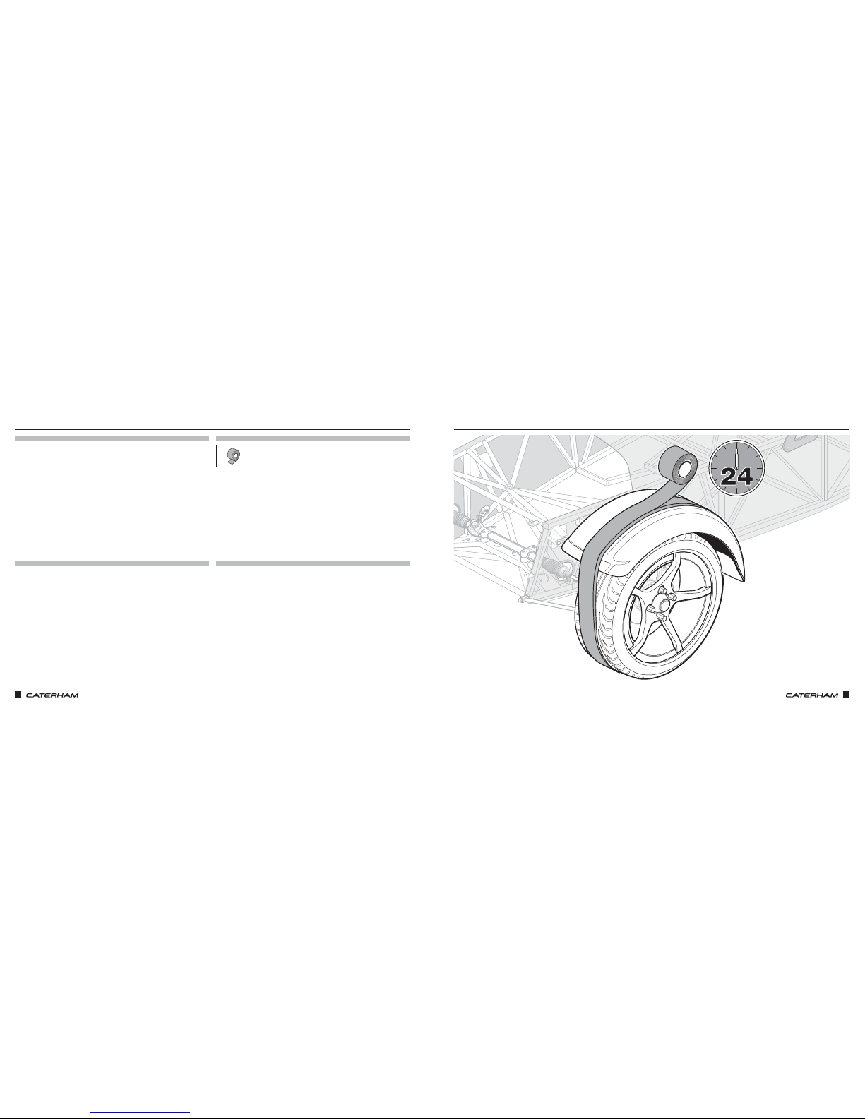
ASSEMBLY GUIDE ASSEMBLY GUIDE
122 123
TAPE IN PLACE FOR 24 HOURS
PARTS
FIXINGS
TOOLS
TIPS
TAPE IN PLACE FOR 24 HOURS
Page 67
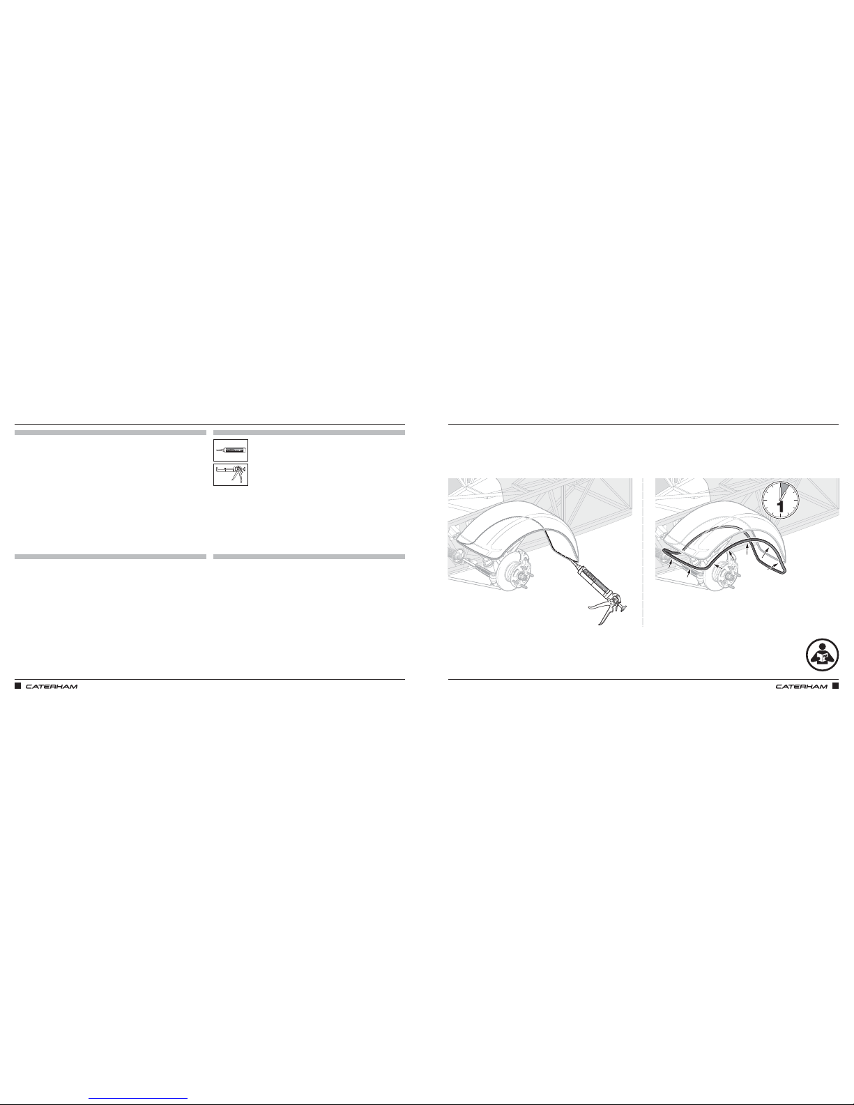
ASSEMBLY GUIDE ASSEMBLY GUIDE
124 125
FINISH WITH TRIMFINISH WITH TRIM
PARTS
FIXINGS
TOOLS
TIPS
Page 68
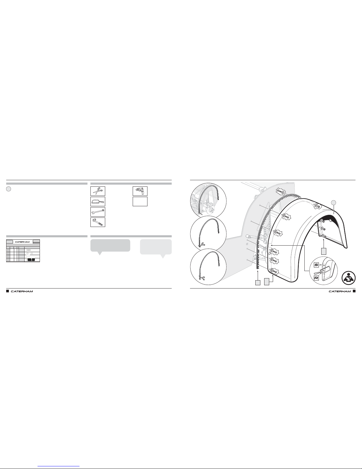
ASSEMBLY GUIDE ASSEMBLY GUIDE
126 127
7
7
FITTING THE REAR WINGSFITTING THE REAR WINGS
PARTS
FIXINGS
TOOLS
TIPS
PART
NUMBER
QTYUSED ON
1QA
SM5X20
20 Rear Wings
2QB
NMYF5
10
Rear wings through
boot
3QC
WP3/16X3/4
30 Wing washers
4QD
76902
4m
Between wing and
body
Drawings are for illustrative purposes only and are not to scale.Page 1 of 1
Nyloc Nut
M5
Plain Washer
3/16" X 3/4"
Wing Piping
1/4" X 1"
REAR WINGS
This pack may include extra fasteners to cover different options
ITEM
BASIC
DESCRIPTION
ILLUSTRATION
Set Screw
M5 X 20
Q
SERIAL
NUMBER
31
Pack
PACK NUMBER
ZFG12
x20
x10
x30
x4
Rear wing
8mm
8mm
1
Cut the supplied piping in half and it
will be enough for both wings.
Rich T
Don’t forget the fuel tank
earth strap gets bolted to
the RH wing bolt.
Tiago O
QB
QC
QD
1
QA
QC
7
7
Sanding Drum
to follow
Page 69
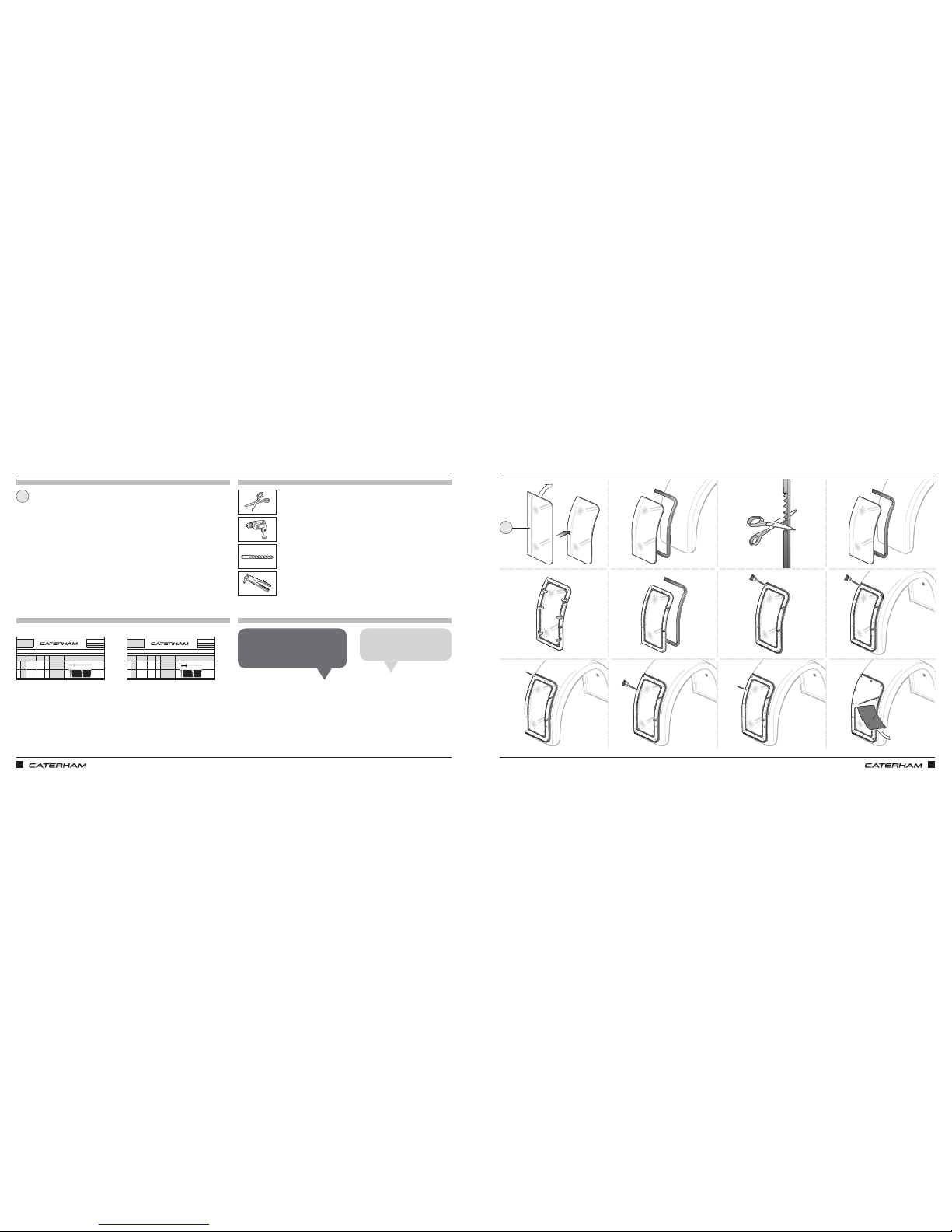
ASSEMBLY GUIDE ASSEMBLY GUIDE
128 129
AND THE WING PROTECTORSAND THE WING PROTECTORS
PARTS
FIXINGS
TOOLS
TIPS
PART
NUMBER
QTYUSED ON
1OA
1661-0414
30
Wing protector to
wing
2OB
76901
2m
Between wing
protector and wing
Drawings are for illustrative purposes only and are not to scale.
Wing Piping
Page 1 of 1
WING PROTECTORS STAINLESS STEEL
This pack may include extra fasteners to cover different options
ITEM
BASIC
DESCRIPTION
ILLUSTRATION
Rivet
1/8" X 0.51"
O
SERIAL
NUMBER
Pack
PACK NUMBER
ZWS01
PART
NUMBER
QTYUSED ON
1PA
1610-01049
30
Wing protector to
wing
2PB
76901
2m
Between wing
protector and wing
Drawings are for illustrative purposes only and are not to scale.Page 1 of 1
Wing Piping
WING PROTECTORS CARBON FIBRE
This pack may include extra fasteners to cover different options
ITEM
BASIC
DESCRIPTION
ILLUSTRATION
Rivet Black
1/8" X 0.51"
P
SERIAL
NUMBER
Pack
PACK NUMBER
ZWS02
Wing protector
"
1
For stainless steel protectors For carbon fibre protectors
x12
x1
x1
1
When drilling through protector start
on the closest edge to the body. This
will help the protector fit correctly.
Chris B
Carbon fibre protectors will not
have the protective film shown.
Anthony L
Page 70
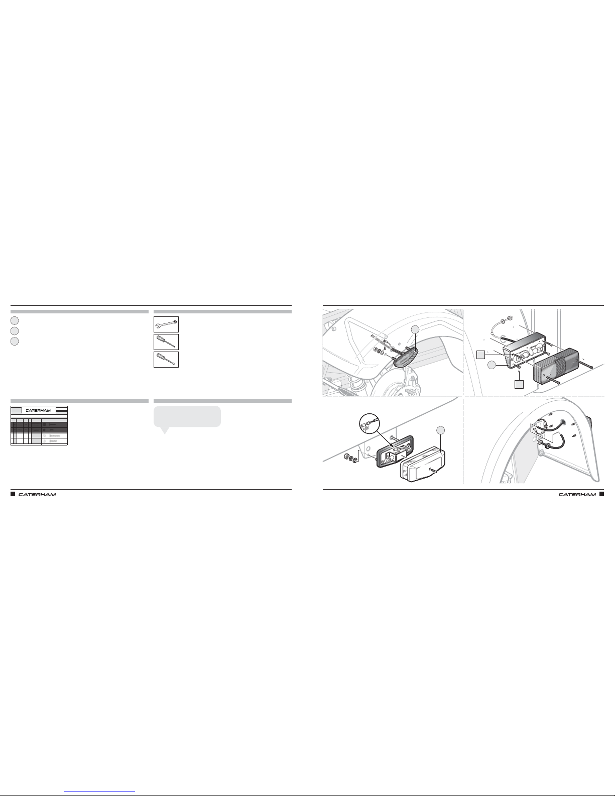
ASSEMBLY GUIDE ASSEMBLY GUIDE
130 131
FITTING THE LIGHTSFITTING THE LIGHTS
PARTS
FIXINGS
TOOLS
TIPS
8mm
PART
NUMBER
QTY USED ON
1 CA
71080
6
Indictor assembly to
indicator pod
2 CB
71077
2
Side repeater earth
on wingstay
3 CC
71079
4
Rear light cluster
upper fixing
4 CD
71078
4
Rear light cluster
lower fixing
Drawings are for illustrative purposes only and are not to scale.
Screw 12 x 1½"
Self tapping
Screw 12 x 1"
Self tapping
BASIC
DESCRIPTION
ILLUSTRATION
Screw 10 x ¾
"
Black Supaflange
Pack
45
SERIAL
NUMBER
Page 1 of 1
PACK NUMBER
30L002B
C
Screw 8 x ½"
Black Supaflange
FASTENER PACK - LIGHTING
ITEM
x4
x4
Side repeater
Numberplate lamp
Rear light
1
3
2
Use a cradle clip & cable tie to keep
the rear light loom out of the way.
John S
CD
CC
1
3
2
Page 71
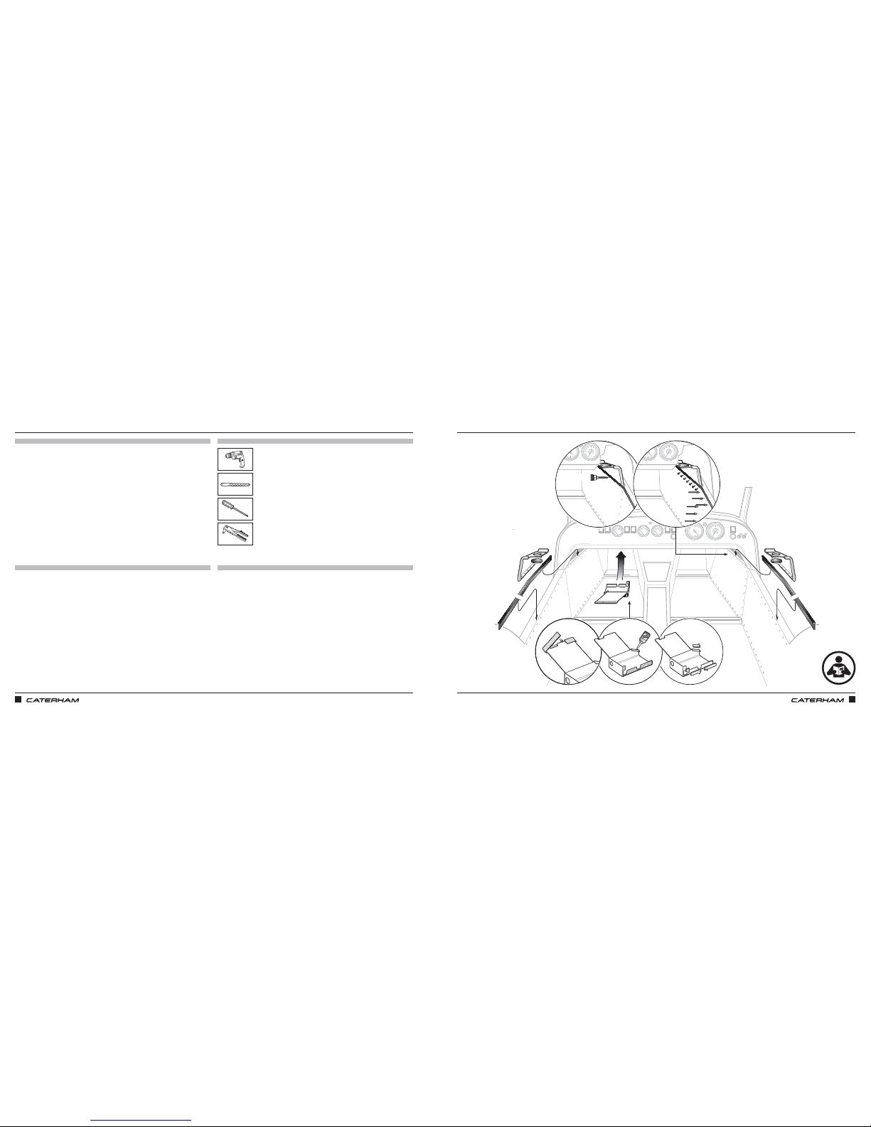
ASSEMBLY GUIDE ASSEMBLY GUIDE
132 133
FUSE BOX COVER & KNEE TRIM PADSFUSE BOX COVER & KNEE TRIM PADS
PARTS
FIXINGS
TOOLS
TIPS
7 x ⁄"
Chassis fastener pack ZCH01 supplied loose:
• Screw ¾" x 10
• Rivet ⁄ x 0.47"
⁄"
Page 72
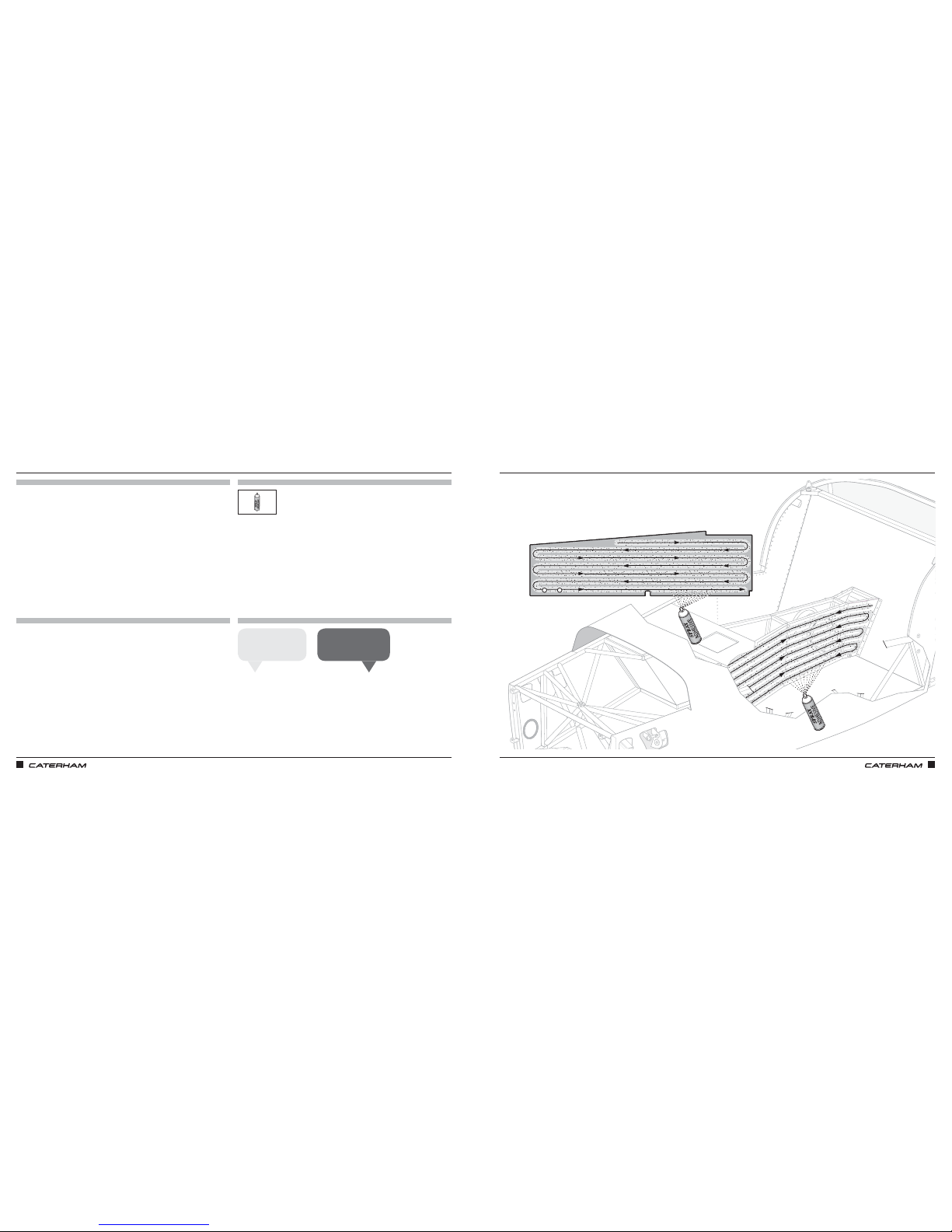
ASSEMBLY GUIDE ASSEMBLY GUIDE
134 135
FIT THE TUNNEL CARPETFIT THE TUNNEL CARPET
PARTS
FIXINGS
TOOLS
TIPS
Spray on both tunnel
panel and carpet.
John K
Allow the adhesive to
go tacky before fitting.
Harry P
Page 73
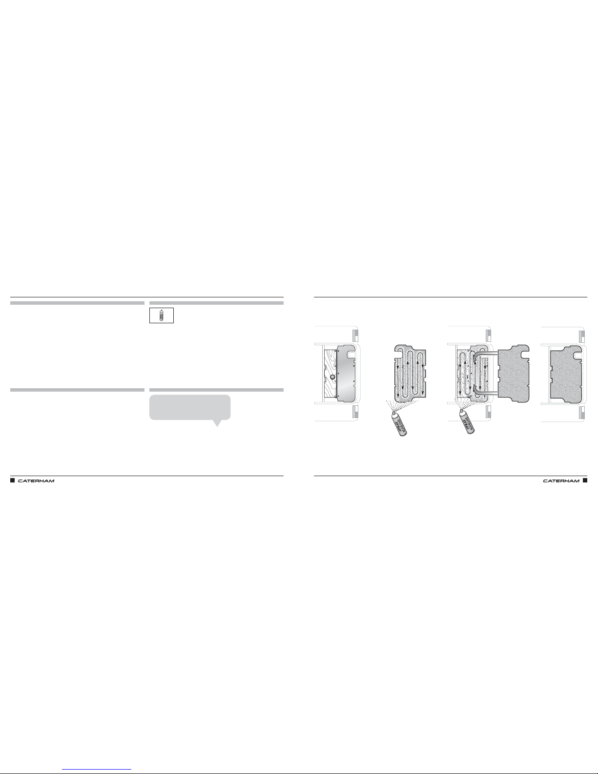
ASSEMBLY GUIDE ASSEMBLY GUIDE
136 137
5 x 1.8mm
3 x ⅛"4 x ⅛"
2 x ½"
x3
x4
x2
AND THE BOOT CARPETAND THE BOOT CARPET
PARTS
FIXINGS
TOOLS
TIPS
S‑Pack cars have a fully carpeted boot. It's
something of a jigsaw pattern, but the parts
are simply glued in place like the bigger bits.
John S
Page 74
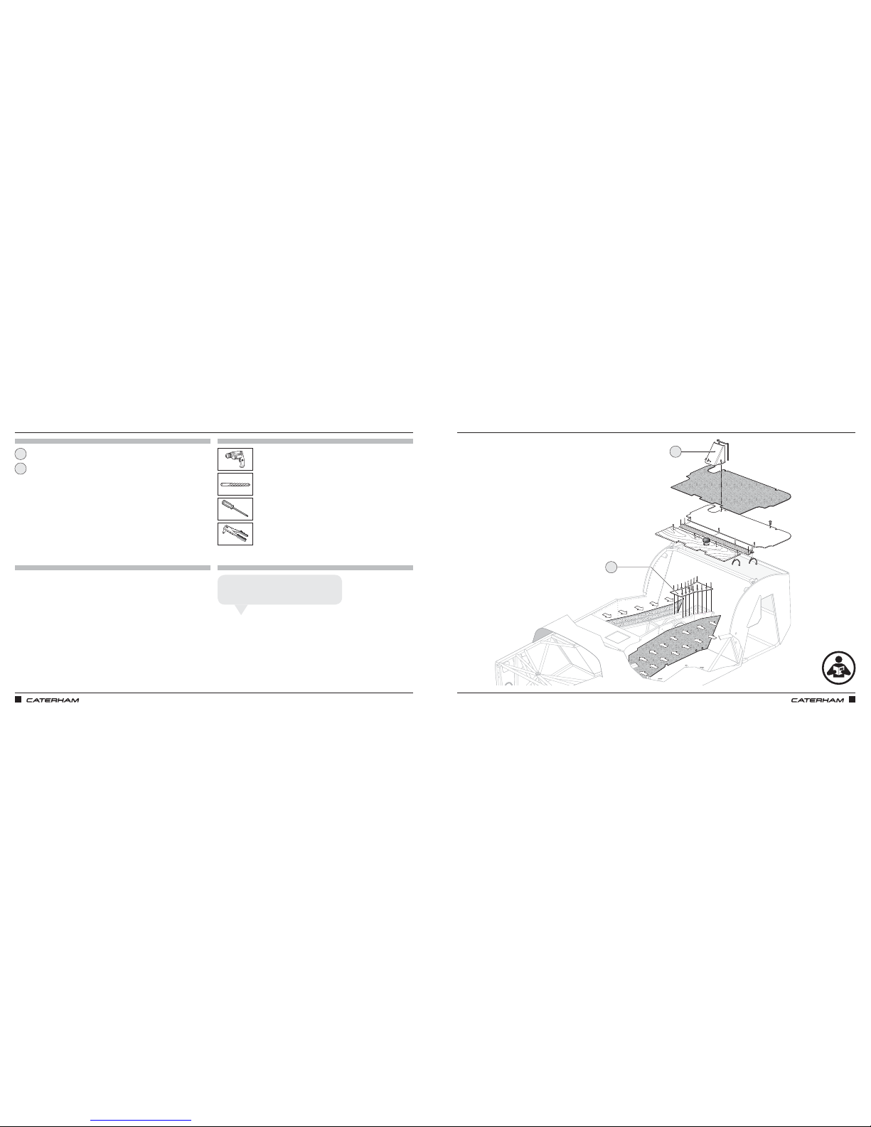
ASSEMBLY GUIDE ASSEMBLY GUIDE
138 139
THIS IS A COVER UP
PARTS
FIXINGS
TOOLS
TIPS
Fuel filler cove
Tunnel closing panel
1
2
THIS IS A COVER UP
Supplied loose:
• Rivets
• Screws
⁄"
The fuel filler cover just screws to the boot floor.
Drill two holes and use self tapping screws.
Rich T
1
2
Page 75
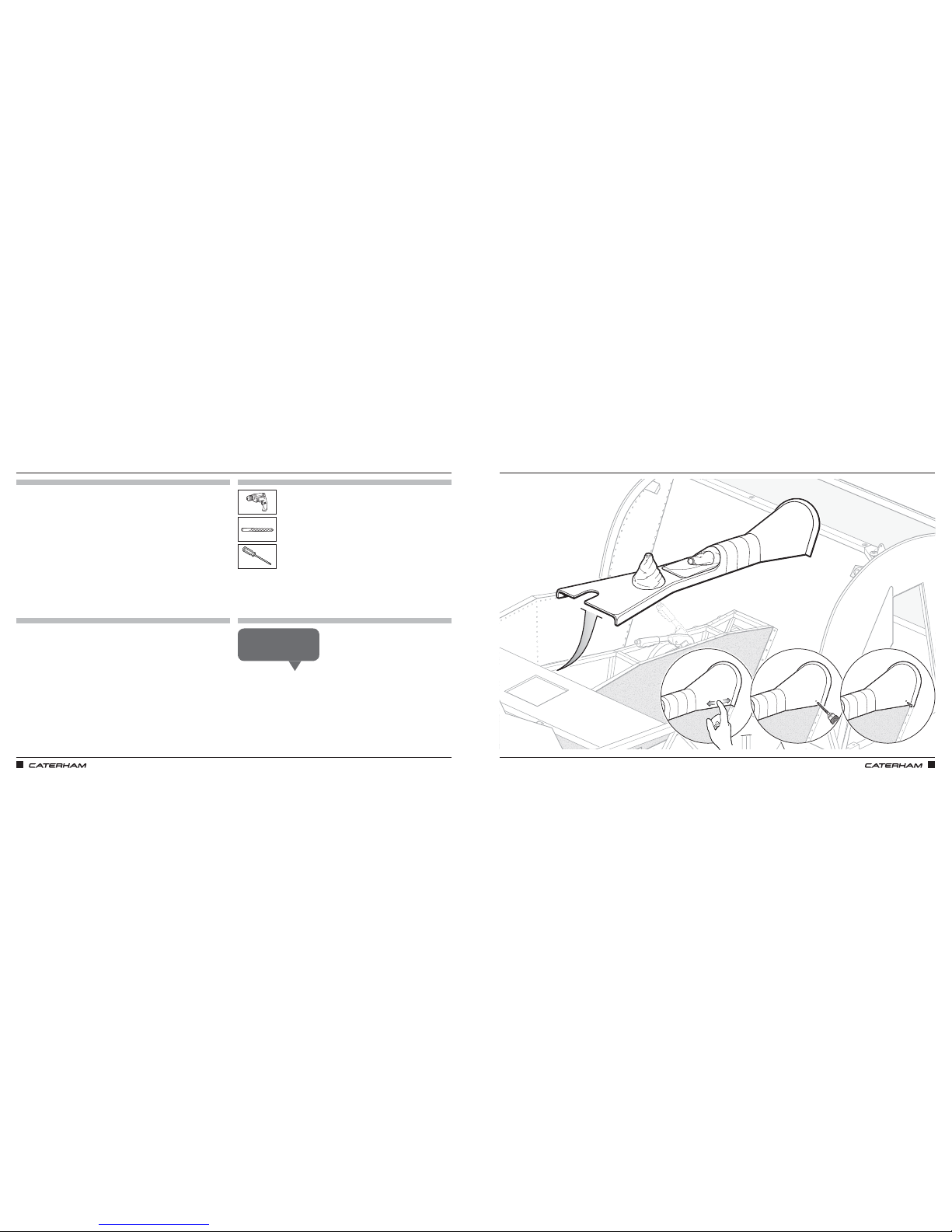
ASSEMBLY GUIDE ASSEMBLY GUIDE
140 141
PARTS
FIXINGS
TOOLS
TIPS
NOW FIT THE TUNNEL TOPNOW FIT THE TUNNEL TOP
The hole can be seen if you
flip the tunnel top over.
Mick F
⅛"
Page 76
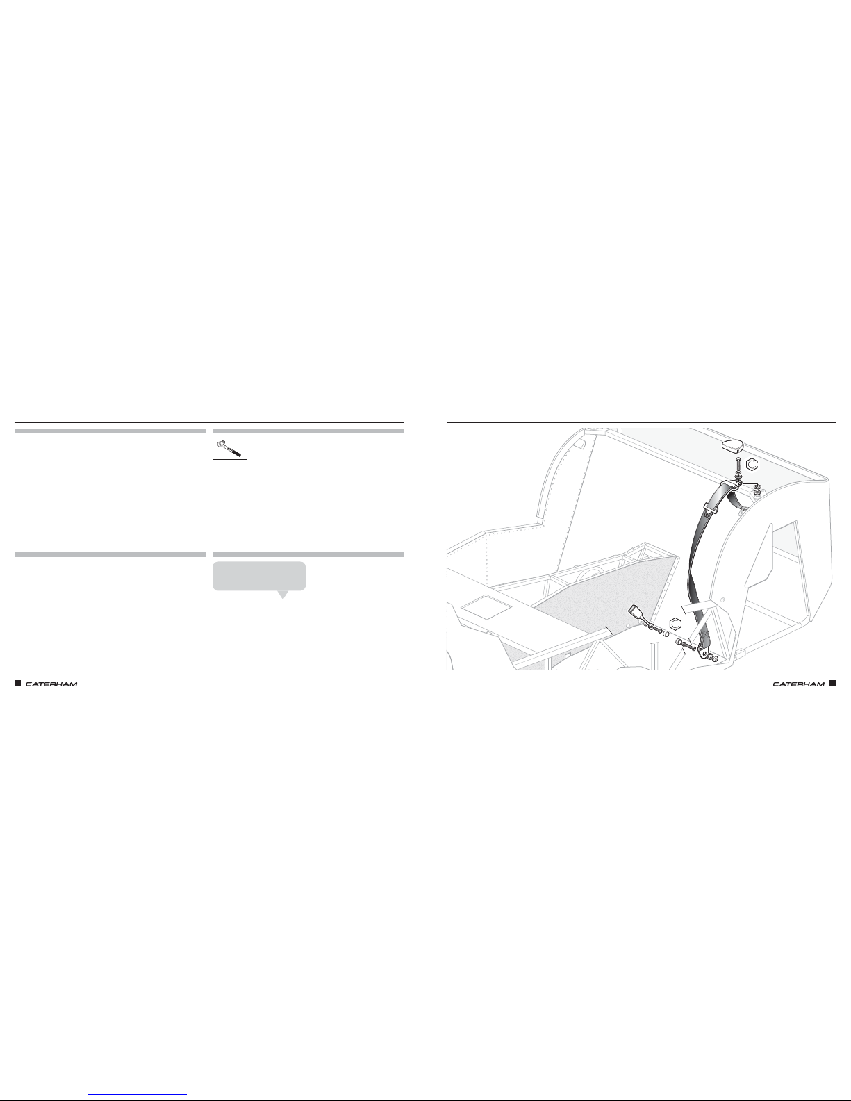
ASSEMBLY GUIDE ASSEMBLY GUIDE
142 143
BELT UPBELT UP
PARTS
FIXINGS
TOOLS
TIPS
Supplied with seat belts
These will be loosely fitted already –
you'll need to tighten & torque.
Chris N
47Nm
47Nm
Page 77
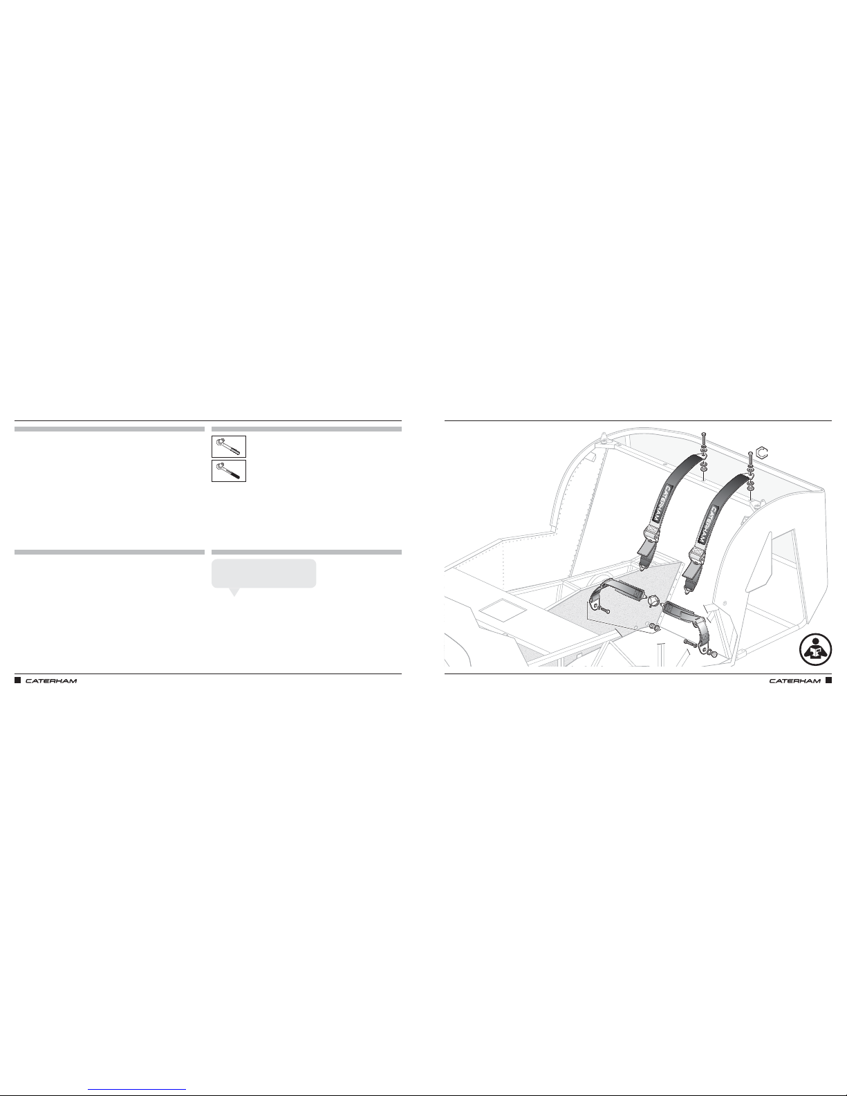
ASSEMBLY GUIDE ASSEMBLY GUIDE
144 145
FITTING THE FOUR-POINT HARNESSFITTING THE FOUR-POINT HARNESS
PARTS
FIXINGS
TOOLS
TIPS
All fixings supplied with the harnesses
17mm
47Nm
The buckle is attached to a lap strap and
this should be fitted to the tunnel side.
Chris N
Page 78
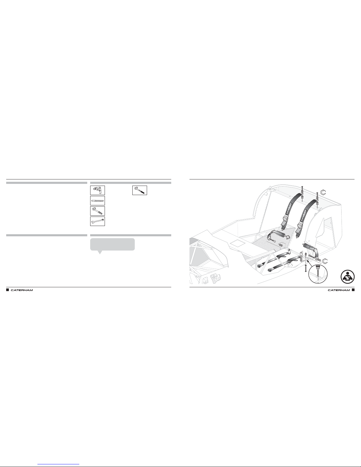
ASSEMBLY GUIDE ASSEMBLY GUIDE
146 147
FITTING THE SIX-POINT HARNESSFITTING THE SIX-POINT HARNESS
PARTS
FIXINGS
TOOLS
TIPS
47Nm
47Nm
All fixings supplied with the harnesses
16mm
17mm
16mm
17mm
⁄"
The buckle is attached to a lap strap and
this should be fitted to the tunnel side.
Lee A
Page 79
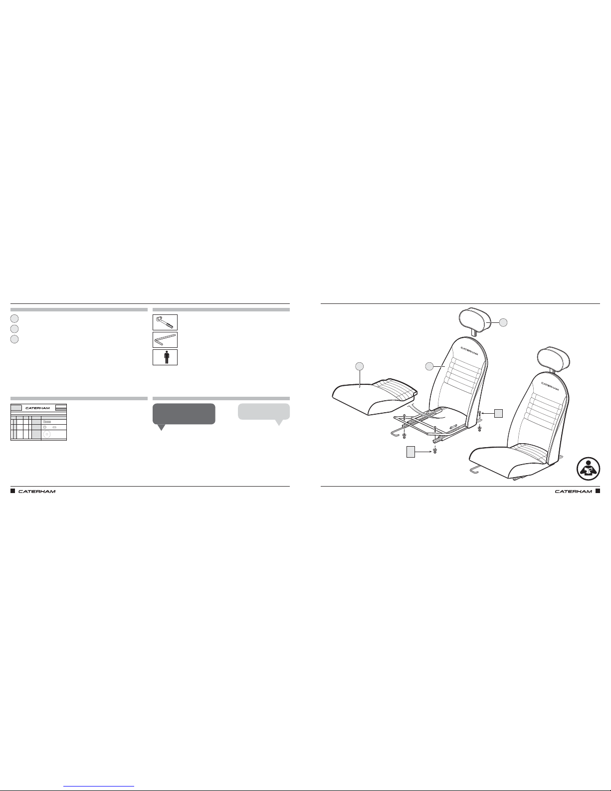
ASSEMBLY GUIDE ASSEMBLY GUIDE
148 149
FITTING CLOTH OR LEATHER SEATS
PARTS
FIXINGS
TOOLS
TIPS
PART
NUMBER
QTYUSED ON
1LA
SMCH8X20
4
Through seat runner
& floor
2LB
NMYF8
4Under floor
3LC
WPH8X30
4Under floor
Drawings are for illustrative purposes only and are not to scale.
Caphead Bolt
M8 X 20
Grade 12.9
L
SERIAL
NUMBER
62
Pack
PACK NUMBER
30Z1058B
Page 1 of 1
Nyloc Nut
M8
Plain Washer
M8 X 30
CLOTH/LEATHER SEATS ALL CARS
This pack may include extra fasteners to cover different options
ITEM
BASIC
DESCRIPTION
ILLUSTRATION
x4
x4
x4
13mm
Seat
Headrest
Seat base
6mm
1
3
2
FITTING CLOTH OR LEATHER SEATS
+
Loosely fit the rear bolts to help
locate the front.
Dan D
Nip up all bolts once fitted.
Anthony L
1
3
2
LB
LC
LA
Page 80
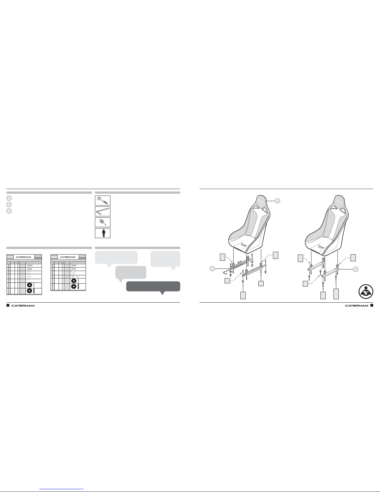
ASSEMBLY GUIDE ASSEMBLY GUIDE
150 151
OR FITTING THE RACE SEATS
PARTS
FIXINGS
TOOLS
TIPS
PART
NUMBER
QTYUSED ON
1MA
BMCH8X25
4
Spacer box section
to seat
2MB
SMCH8X20
4
Floor to rivnut in
spacer box section
3MC
WSH5/16
8Bolt heads
4MD
WP5/16X1.1/4
4Under floor
5ME
WPM8X18X1
4
Spacer box section
to seat
7MF
TW2
3
Seat spacer
8MG
TW3
5
Seat spacer
Drawings are for illustrative purposes only and are not to scale.
Pack
PACK NUMBER
30Z1062A
Washer
5/16" X 1 1/4"
M
SERIAL
NUMBER
63
Caphead Bolt
M8 X 20
Spring Washer
5/16"
SEATS FIXED TILLETT RACING
This pack may include extra fasteners to cover different options
ITEM
BASIC
DESCRIPTION
ILLUSTRATION
Caphead Bolt
M8 X 25
Washer
M8 X 18
Spacer Black
Plastic
Page 1 of 1
Spacer Black
Plastic
PART
NUMBER
QTYUSED ON
1NA
BMCH8X25
4Runner to seat
2NB
SMCH8X20
4Runner to floor
3NC
WP5/16X1.1/4
4
Under floor
4ND
NMYF8
4Under floor
5NE
TW2
3Seat spacer
6NF
TW3
5
Seat spacer
Drawings are for illustrative purposes only and are not to scale.
Spacer Black
Plastic
Spacer Black
Plastic
Page 1 of 1
Caphead Bolt
M8 X 20
Washer
5/16" X 1 1/4"
Nyloc Nut
M8
SEATS ADJUSTABLE TILLETT RACING
This pack may include extra fasteners to cover different options
ITEM
BASIC
DESCRIPTION
ILLUSTRATION
Caphead Bolt
M8 X 25
N
SERIAL
NUMBER
64
Pack
PACK NUMBER
30Z1063A
x4
x4
x8
x4
x4
x3
x5
x4
Seat
Fixed seat spacer
Adjustable runner
x4
x4
x4
x3
x5
1
3
2
OR FITTING THE RACE SEATS
13mm
6mm
+
LOCTITE
LOCTITE
Put a bit of Loctite on bolts that go
into the seat on the runner version.
Chris B
Runners / seat spacers
can be fitted to seat
before putting in car.
Mick F
Loosely fit the rear bolts
to help locate the front.
Harry P
The fixed position seat is for the passenger side!
Chris N
1
3
2
NF
NF
MF
MF
NC
ND
MB
MC
MD
MC
ME
NE
NF
MF
MG
NA
NB
MA
For adjustable seatsFor fixed seats
Page 81
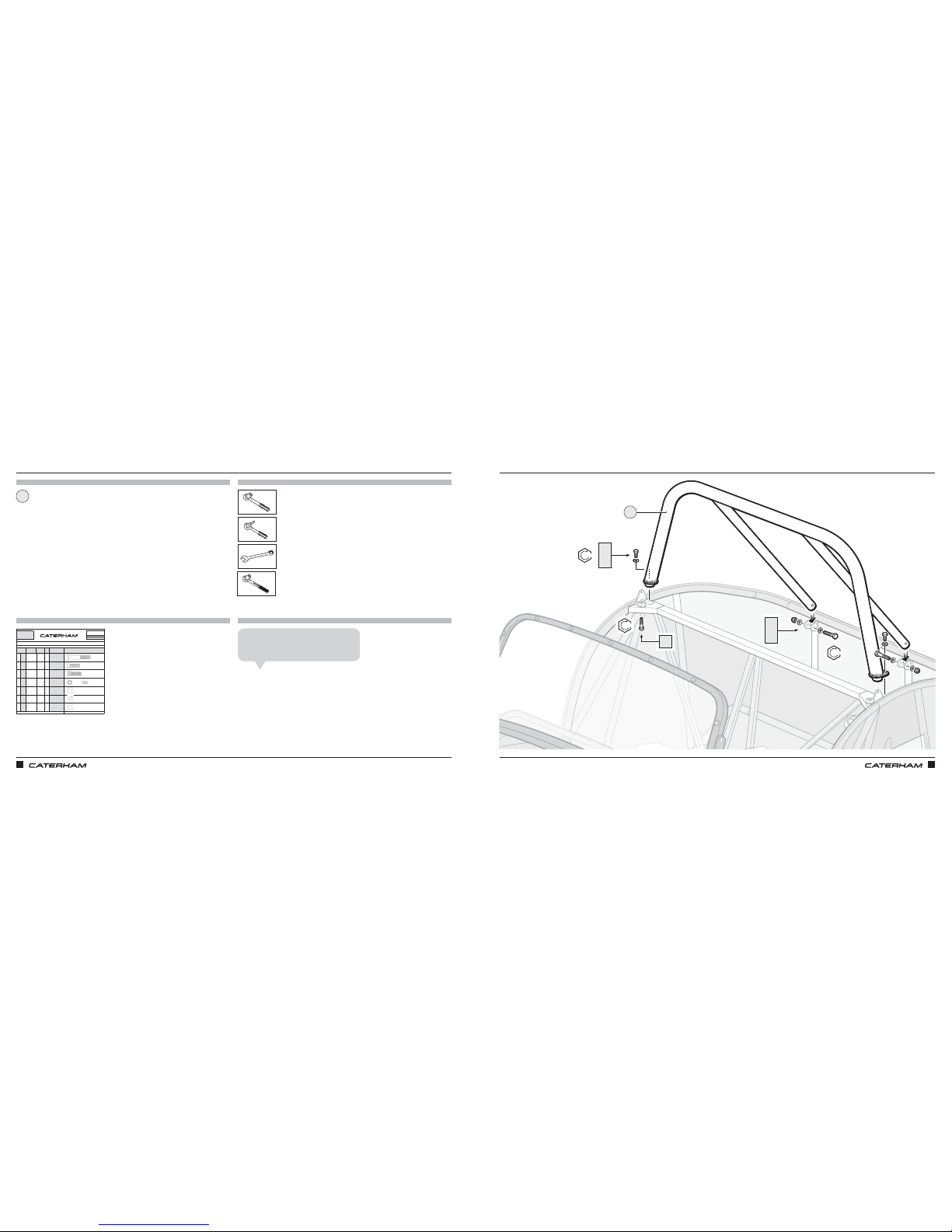
ASSEMBLY GUIDE ASSEMBLY GUIDE
152 153
FITTING THE ROLL OVER BARFITTING THE ROLL OVER BAR
PARTS
FIXINGS
TOOLS
TIPS
PART
NUMBER
QTYUSED ON
1JA
BM10X60
2
Rear diagonals of
roll over bar to
mounting brackets
2JB
SM8X20
2
Roll over bar bracket
to chassis
3JC
BMCH10X20
2Roll over bar boss
4JD
NMYF10
2
Rear diagonals of
roll over bar to
mounting brackets
5JE
WPHM8
2
Roll over bar bracket
to chassis
6JF
WSHM8
2
Roll over bar bracket
to chassis
7JG
WPHM10
4
Rear diagonals of
roll over bar to
mounting brackets
Drawings are for illustrative purposes only and are not to scale.Page 1 of 1
Plain Washer
M8
Spring Washer
M8
Plain Washer
M10
Setscrew
M8 X 20
Grade 8.8
Caphead Bolt
M10 X 20
Nyloc Nut
M10
ROLL OVER & TRACK DAY BAR SERIES 3 METRIC
This pack may include extra fasteners to cover different options
ITEM
BASIC
DESCRIPTION
ILLUSTRATION
Bolt M10 X 60
Grade 8.8
J
SERIAL
NUMBER
47
Pack
PACK NUMBER
30P010A
x2
x2
x2
x2
x2
x2
x4
Roll over bar
1
If you've fitted the rear dampers they'll
need to come off again to do this properly.
Chris B
1
JB
JE
JF
JA
JD
JG
13mm
17mm
8mm
17mm
47Nm
47Nm
25Nm
JC
Page 82
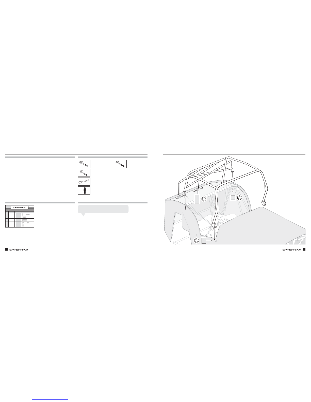
ASSEMBLY GUIDE ASSEMBLY GUIDE
154 155
OR THE ROLL CAGE FOR ACADEMY CARS
PARTS
FIXINGS
TOOLS
TIPS
PART
NUMBER
QTYUSED ON
1KA
BM10X60
2
Rear diagonals of
roll over bar to
mounting brackets
2KB
SM10X16
4Front cage bracket
3KC
BMCH10X20
2Roll over bar boss
4KD
NMYF10
2
Rear diagonals of
roll over bar to
mounting brackets
5KE
WPHM10
8
x 4 Front cage
bracket x4
Rear diagonals
Drawings are for illustrative purposes only and are not to scale.Page 1 of 1
Plain Washer
M10
Setscrew
M8 X 16
Grade 8.8
Caphead Bolt
M10 X 20
Nyloc Nut
M10
ROLL CAGE SERIES 3 METRIC
This pack may include extra fasteners to cover different options
ITEM
BASIC
DESCRIPTION
ILLUSTRATION
Bolt M10 X 60
Grade 8.8
K
SERIAL
NUMBER
47
Pack
PACK NUMBER
30P017A
x2
x4
x2
x2
x8
OR THE ROLL CAGE FOR ACADEMY CARS
+
17mm
8mm
17mm
Mask up the paintwork before fitting to avoid scratches.
John S
KA
KE
KD
47Nm
47Nm
47Nm
KB
KE
JC
Page 83
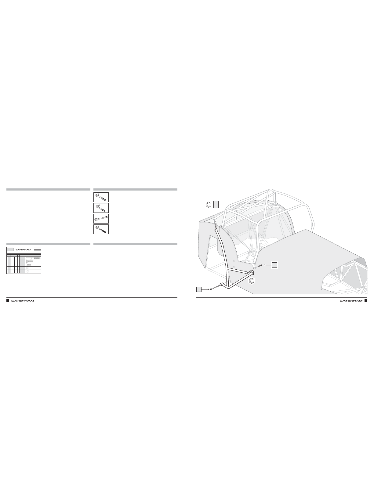
ASSEMBLY GUIDE ASSEMBLY GUIDE
156 157
PARTS
FIXINGS
TOOLS
TIPS
AND THE SIDE IMPACT BARAND THE SIDE IMPACT BAR
17mm
19mm
⁄"
19mm
PART
NUMBER
QTYUSED ON
1RA
BM12X120
1 A-frame
2RB
BFCH7/16X1.5
1
Boss on top of
chassis
3RC
SM10X25
1Front cage bracket
4RD
WPHM10
1Front cage bracket
5RE
WSH7/16
1
Boss on top of
chassis
Drawings are for illustrative purposes only and are not to scale.
R
SERIAL
NUMBER
46
Pack
PACK NUMBER
30P009C
SIDE PROTECTION BAR SERIES 3
This pack may include extra fasteners to cover different options
ITEM
BASIC
DESCRIPTION
ILLUSTRATION
Bolt M12 X 120
Grade 10.9
Spring Washer
7/16"
Page 1 of 1
Caphead Bolt
7/16" X 1 1/2"
Set screw M10
X 25 Grade
10.9
Plain Washer
M10
x1
x1
x1
x1
x1
Use washers from rollcage pack
47Nm
47Nm
RA
RB
RE
RC
Page 84
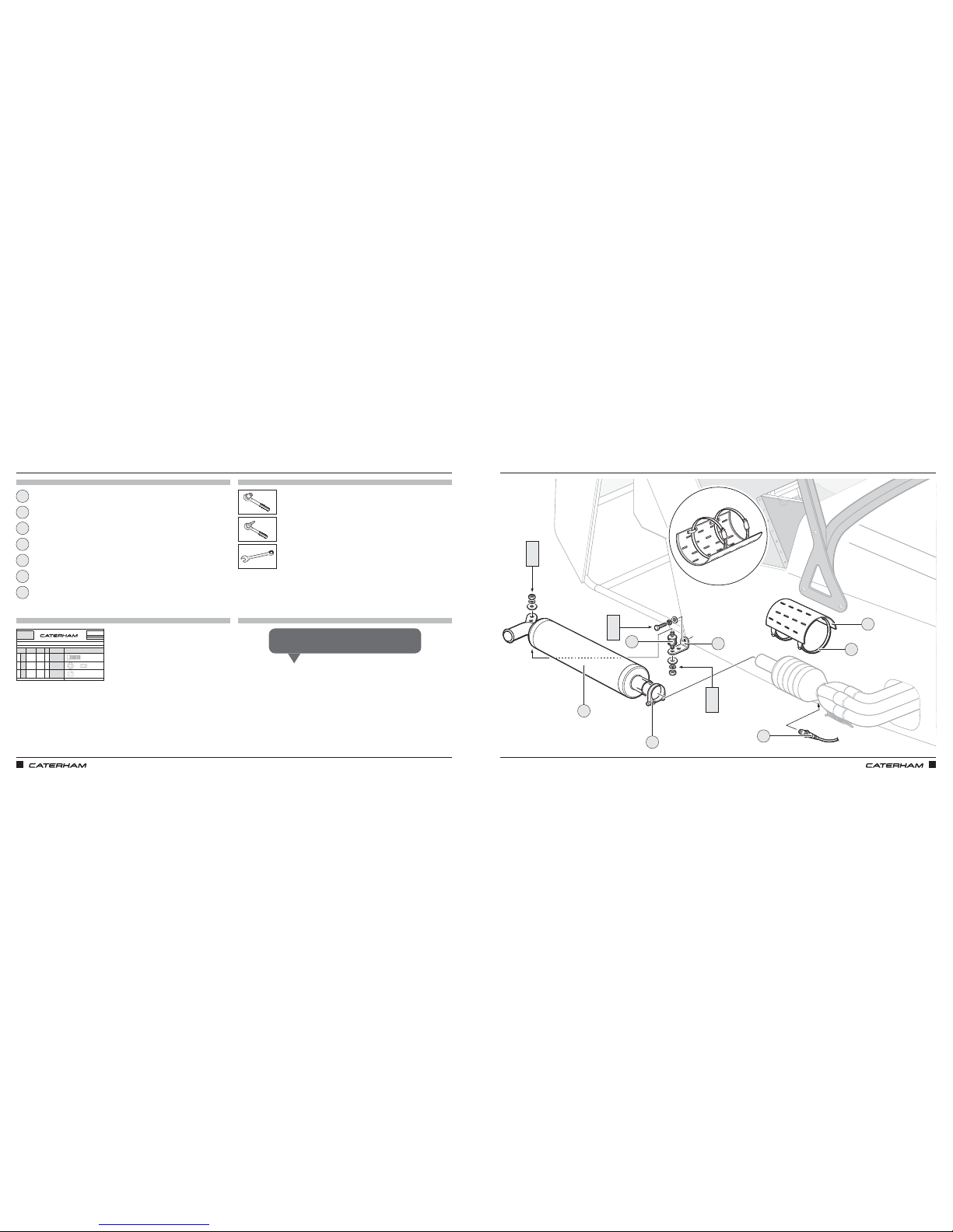
ASSEMBLY GUIDE ASSEMBLY GUIDE
158 159
PARTS
FIXINGS
TOOLS
TIPS
PART
NUMBER
QTYUSED ON
1GA
SM8X25
1
Exhaust Mounting
Bracket
2GB
NFPF8
2 Exhaust Bobbin
3GC
WSHM8
3
x 1 Exhaust
Mounting Bracket x
2 Exhaust Bobbin
Drawings are for illustrative purposes only and are not to scale.Page 1 of 1
Plain Nut
M8
Spring Washer
M8
EXHAUST
This pack may include extra fasteners to cover different options
ITEM
BASIC
DESCRIPTION
ILLUSTRATION
Setscrew
M8 X 25
Grade 8.8
G
SERIAL
NUMBER
56
Pack
PACK NUMBER
30X020B
x1
x2
x3
Silencer
Lambda sensor
Silencer mounting bracket
Exhaust clamp
Clip
Cat guard
Exhaust mounting bobbin
1
3
6
2
5
4
7
EVEN MORE EXHAUSTING EVEN MORE EXHAUSTING
4
7
GA
GC
GD
GB
GC
GD
1
2
3
5
6
Cable tie the Lambda sensor lead neatly out of the way.
Lee A
7mm
10mm
13mm
⅞"
19mm
GB
GC
GD
Page 85
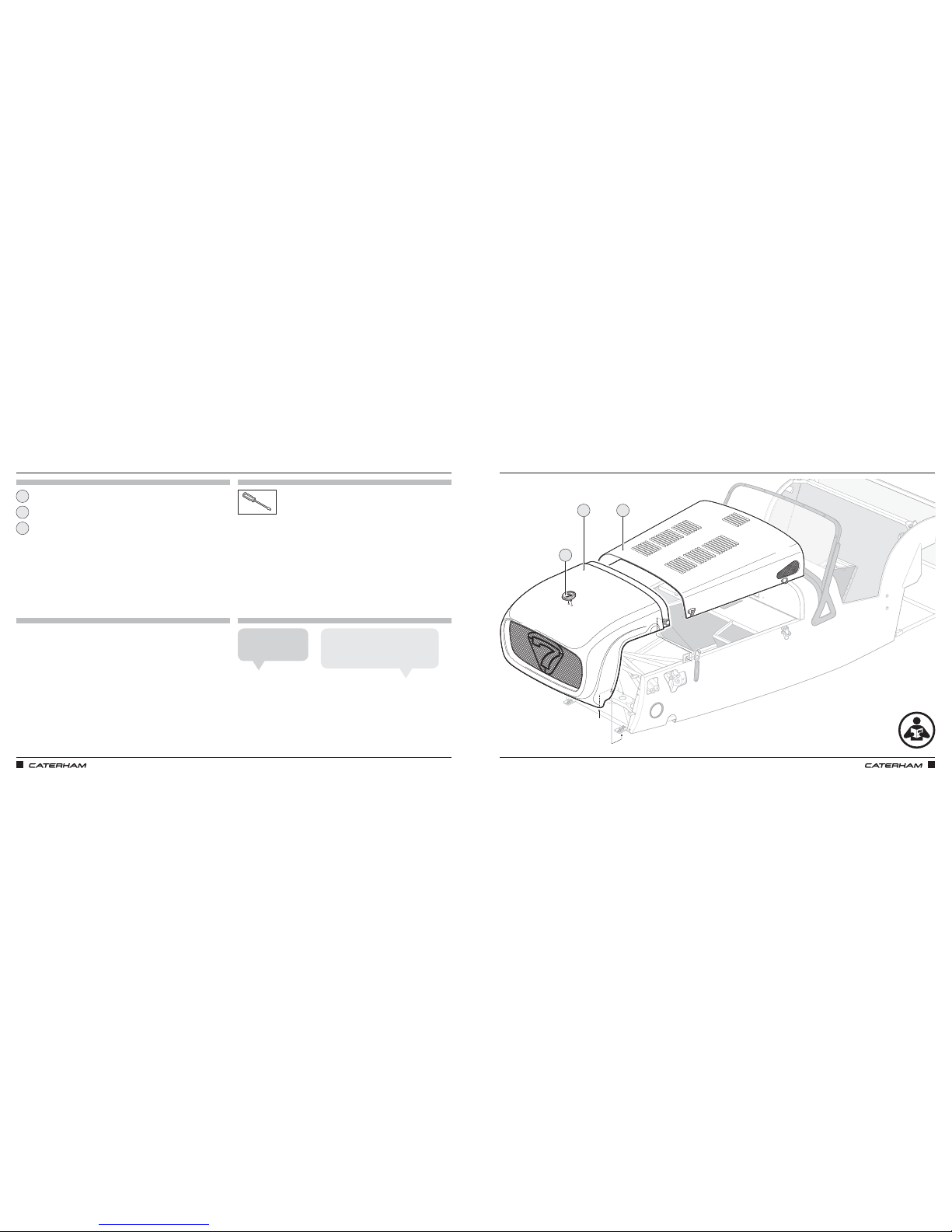
ASSEMBLY GUIDE ASSEMBLY GUIDE
160 161
THE NOSE CONE BADGE
PARTS
FIXINGS
TOOLS
TIPS
Nose cone
Badge
Bonnet
1
3
2
THE NOSE CONE BADGE
The nose cone goes on
before the bonnet.
Anthony L
Stick the supplied foam around the edge
of the nose and scuttle where the bonnet
will sit (if you've not done already).
Harry P
3
1
2
Page 86
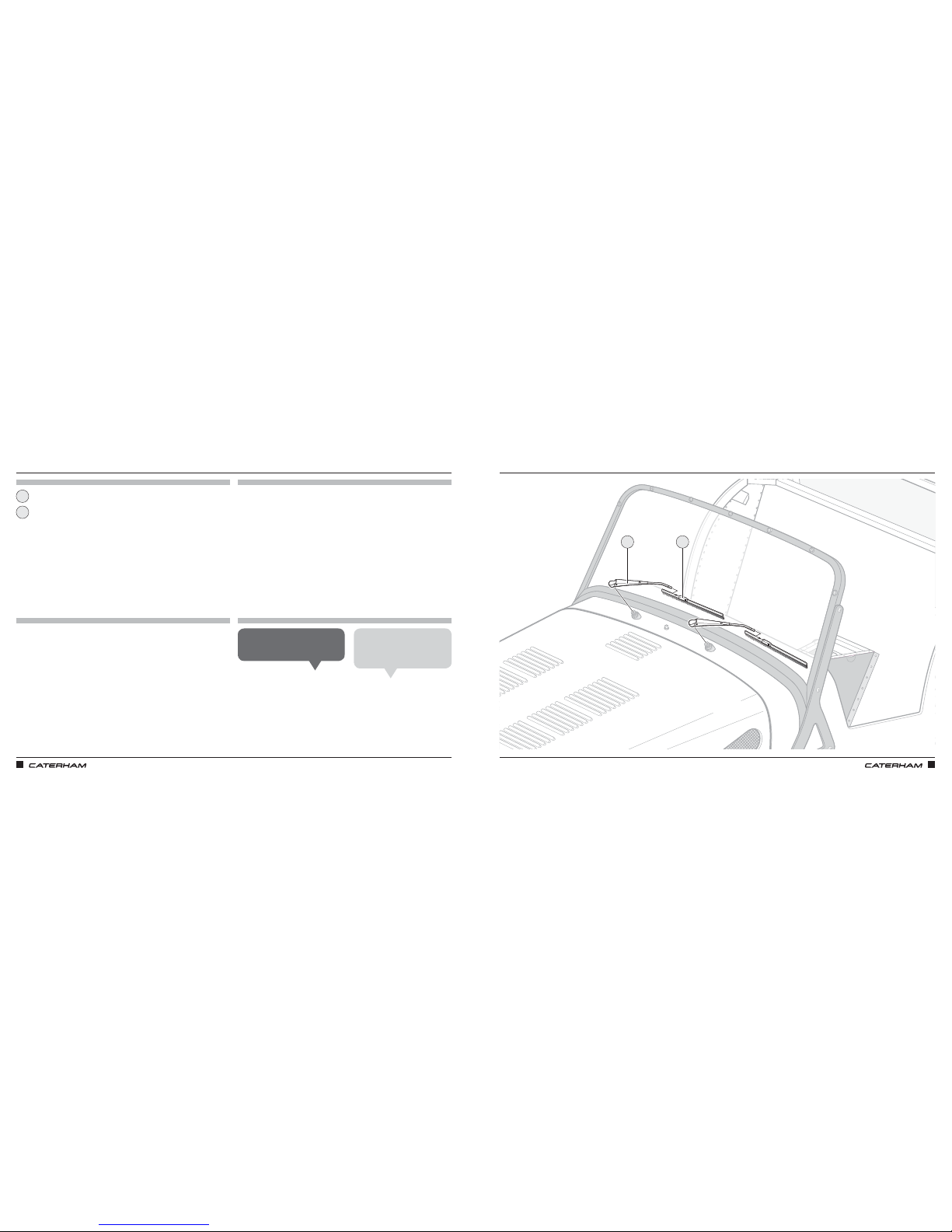
ASSEMBLY GUIDE ASSEMBLY GUIDE
162 163
FITTING THE WIPERS
PARTS
FIXINGS
TOOLS
TIPS
Wiper arm
Wiper blade
1
2
FITTING THE WIPERS
Ensure wipers are in paused position
before fitting the wiper arms.
John S
Now would be a good time to fill
the washer bottle with fluid and
test the washers and wipers.
Chris B
1 2
Page 87
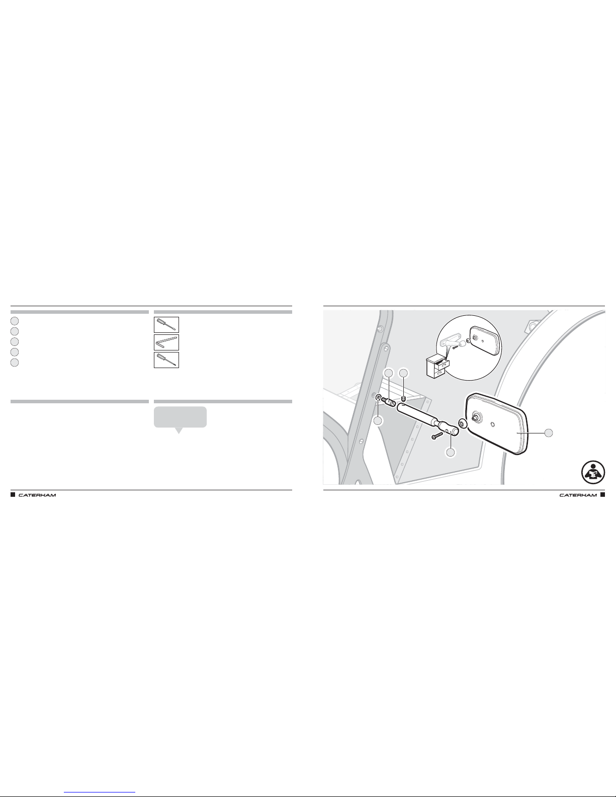
ASSEMBLY GUIDE ASSEMBLY GUIDE
164 165
PARTS
FIXINGS
TOOLS
TIPS
Mirror head
Mirror mount stud
Mirror mount
Fibre washer
Grub screw
25mm
T20
00
00
00
00
00
AND FINALLY, AT LAST, THE WING MIRRORSAND FINALLY, AT LAST, THE WING MIRRORS
Wing mirror bag
You may have to unclick the
glass out to tighten up.
Mick F
1
2
4 3
5
Page 88

ASSEMBLY GUIDE ASSEMBLY GUIDE
166 167
THE LAST FEW STEPS…
Your car is almost complete, but before you can drive triumphantly out of the garage (and legally, as far as
the end of your driveway) there are a few important things that need to be done. These are, bleeding the
brakes and preparing the engine for the its first grand firing-up ceremony (it will feel like that, even if you are
doing it on your own).
So, on with bleeding the brakes which cannot be explained with a simple diagram unfortunately:
Assemble the things you’ll need: Brake fluid, both a 10mm and an 11mm spanner, a length of washer
hose (or similar clear plastic hose) and a waster fluid receptacle (some form of used bottle is ideal;
you won’t want to use it again after this)
Find a volunteer. They need to be able to reach and press the brake pedal, plus respond to your
instructions, so whilst a child is fine for this job, someone’s might be more inclined to listen to you.
Fill the brake master cylinder with fresh brake fluid and leave the cap o. BE CAREFUL NOT TO
SPILL ANY ONTO THE PAINTWORK; if you do, wipe it o immediately. Brake fluid will react with the
paintwork causing it to blister and peel.
Starting at the left rear corner, locate the bleed nipple on the caliper. It will have a rubber cap on it.
Remove the cap, remember where you put it, and attach the washer hose to the nipple and put the
other end in the waste bottle. This sometimes needs the hose warming up in a cup of hot water to
allow it to stretch over the nipple.
Using the 10mm spanner, ‘crack o’ the nipple about half of a turn.
Ask your assistant to pump the pedal a few times. You should see bubbly fluid flowing through the
pipe. When the bubbles die down, ask them to hold the pedal down, then tighten the nipple back up.
Check and top of the fluid level in the reservoir as necessary.
Ask them to lift o, then pump it a couple of times, then press the pedal down and hold it down.
Crack o the nipple again and let the fluid and bubbles flow. It will stop flowing as soon as your
assistant has run out of brake pedal travel. Tighten the nipple.
Repeat steps 8 and 9 until you get 100% bubble free fluid passing through the pipe, remembering to
check and top up the reservoir. You will waste quite a lot of brake fluid during this process.
Once you are satisfied that there are no more bubbles (no more air in the caliper), then you can
remove the washer hose and refit the dust cover.
Repeat steps 5 to 10 for the remaining brakes in this order, right rear next, then right front and lastly
left front. The front brake nipples use an 11mm spanner.
Although tedious, getting all the air out of the braking system is important and will give you a good,
firm brake pedal, which is what you need; not a soft spongy one like you have in a regular car. You
may need to repeat the whole process after the first drive or two (or even after the car has had a ride
on a trailer); air in the braking system is very good at hiding.
6
5
7
8
9
10
11
12
1
2
3
4
Page 89
ASSEMBLY GUIDE ASSEMBLY GUIDE
168 169
Brakes bled and we are ready to fire up the engine. Again, it’s easier to explain in writing than draw a
diagram. The only thing you’ll need for this job is to ensure that you have put some fuel in the car. The
shape of the Caterham fuel tank does not lend itself to making use of every last drop, so we recommend
an absolute minimum of 10 litres in the tank before trying to start the car. With the tank filled, we are ready
forinitialisation.
But before anything else:
YOU DID REMEMBER TO PUT OIL IN THE ENGINE AND GEARBOX, RIGHT?
Reassure yourself the engine is full of oil.
Disconnect the inertia switch; it’s the black thing attached to the engine bay bulkhead under the
windscreen that has rubber cap on top and a plug with two wires connecting from underneath. By
disconnecting the inertia switch, the fuel pump will not work, so intentionally, the engine will not fire.
Ensure the gearbox is in neutral, then turn the ignition key and press and hold the start button.
As the engine cranks over, watch the oil pressure gauge. Keep cranking until the needle starts to
climb, then steadies out.
We now have oil pressure circulating in the engine, which means the engine is ready to be started.
Reconnect the inertia switch.
Take a deep breath, mutter 'this is it', cross your fingers and brace yourself.
Turn the ignition key, press and hold the start button. It will take a few moments for the fuel to get
through, so do not expect an instant start.
All things willing, the engine will start. Hooray! If it stops straight away, don’t worry. Try again and once
it starts give it a little rev.
That’s it. Your car is complete! Well done – you have built a car; a real live car; not many people can say
that. If you remembered to put in gearbox and dierential oil, and fill the system with coolant, then a
tentative edge out onto the driveway is in order. You’ll need to pop the wheels on first and lower it from
the axle stands.
Let’s just run through that quickly:
i. Put a wheel on and do the nuts up a few turns by hand (to ensure they do not cross-thread).
ii. Tighten them up the best you can with the wheels o the ground.
iii. Lower the car from the axle stands, front first; taking care that it doesn’t lean back on the axle
stands at the back (a helper might be handy).
iv. Torque the wheel nuts to 65lbft (about 85Nm).
v. That’s it, you’re ready to go!
Take care and good luck with the IVA and registration process.
You will soon be experiencing the sheer pleasure of being a Caterham driver. Once again, enjoy!
1
2
3
4
6
5
7
8
9
Page 90

Content is sub ject to change without notice.
© Caterham 2 017
Edition 1.0 1 2/17
Images are for illustrative purpose s only.
Caterham Cars Limited, 2–3 Kennet Road, Dartford, Kent, DA1 4QN
+44 (0) 1322 625800
/CaterhamCars @caterhamcars
 Loading...